Download to read offline

![International Research Journal of Engineering and Technology (IRJET) e-ISSN: 2395 -0056
Volume: 04 Issue: 02 | Feb -2017 www.irjet.net p-ISSN: 2395-0072
© 2017, IRJET | Impact Factor value: 5.181 | ISO 9001:2008 Certified Journal | Page 1572
effective series transmission impedance from the sending
end to the receiving end. The relationship characterizes the
power transmission over a single line is
P = V 2 sin (δ)……………………………………….. (2)
X
Where,
P - Real power transmission over a single line
V - The sending end and receiving end voltage
(assuming Vs = VR = V)
X - The line impedance
δ - The power angle
SSSC is a power converter connected in series with
the transmission line and it injects a voltage in quadrature
with the line current to emulate a series capacitive or
inductive reactance into the transmission line. A SSSC
equipped with energy storage system and/or absorbing is
also able to exchange real power with power system.
Reactive power exchange is controlled by the magnitude of
the injected voltage to the transmission line, and angle
control is used to regulate the active power exchange. The
inductive or capacitive mode of operation is set by the
injected voltage phaseangle withrespecttothetransmission
line current.
When injected voltage is leading the line current,
reactive power is absorbed and SSSC operates in inductive
mode. In capacitive mode injected voltage is lagging the line
current and injects reactive power to the transmission line.
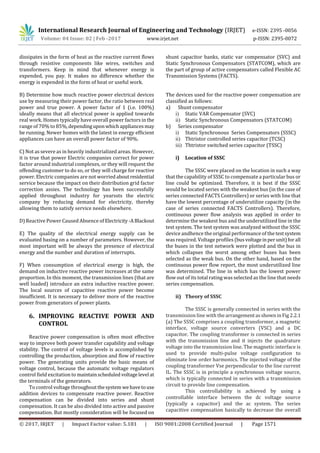
Fig. 2: Simplified diagram of SSSC
In the equivalent circuit of an SSSC compensated system,the
SSSC is represented by a voltage source and impedance
(Lr,Rr). The SSSC is connected between buses 1 and 2. The
pair (L1, R) represents the line and L2represents a
transformer.
iii) Rating of the SSSC
The SSSC can provide capacitive or inductive
compensating voltage independent of the line current. The
VA rating of the SSSC (solid-state inverter and coupling
transformer) is simply the product of the maximum line
current (at which compensation is still desired) and the
maximum series compensating voltage: VA = ImaxVmax. An
SSSC of 1 p.u. VA rating coversa control rangecorresponding
to 2 p.u. compensating VARs, that is the control range is
continuous from -1 p.u. (inductive) VARs to +1 p.u.
(capacitive) VARs.
7. CONCLUSION
It has been studied that the static synchronous series
compensator (SSSC) is able to control the power flow in the
transmission line. It can also inject fast changing voltage in
series with the line irrespective of the magnitude and phase
of the line current. The SSSC can also damp out the
oscillations of the system.
REFERENCES
[1] A.H. Norouzi and A.M. Sharaf, “Two Control schemes
to enhance the Dynami Performance of the
STATCOM and SSSC”, IEEETrans.onPowerDelivery,
Vol 20, Number 1, Jan 2005, pp 435.
[2] Hao, S.H., Papalexopoulos, A. “Reactive Power
Pricing and Management “. IEEE Transactions on
Power Systems, Vol. 12, No.1, February 1997.
[3] L. Gyugyi, “Dynamic compensationofactransmission
lines by solid-state synchronous voltage sources”,
IEEE Trans. On Power Delivery, Vol. 9, No. 2, April
1994.
[4] Miller, T.J. (Editor),"Reactive Power: Basics,
Problems and Solutions”.IEEETutorialcourse. 1987.
[5] N.G. Hingorani, L. Gyugyi, “Understanding FACTS:
Concepts and technology of flexible ac transmission
Systems”, IEEE Press, Piscataway, New Jersey, 1999
ISBN 0-7803-3455
[6] Sharm, V. P. ,“A Static Synchronous Series
Compensator (SSSC): An approach for
reactivepower compensation for the transmission
system.” IJIRT, volume 1, Issu10,Augst 2014
[7] S. Lee, H. Kim, S. Sul, and F. Blaabjerg, “A novel
control algorithm for static series compensation by
use of PQR instantaneous power theory”, IEEE
Trans. on Power Electronics, Vol. 19, No. 3, May
2004, pp 814-827
[8] Silva, L., KundurXu, W., Zhang,Y.,da,P.”Competitive
Procurement of Dynamic Reactive Power Support
Service for Transmission Access”. IEEE Summer
Power Meeting 2000. Whitehead, A. “A New Market
in Reactive Power”. Birmingham, UK. April1998.
[9] S. Lee, H. Kim, S. Sul, and F. Blaabjerg, “A novel
control algorithm for static series compensation by
use of PQR instantaneous power theory”, IEEE
Trans. on Power Electronics, Vol. 19, No. 3, May
2004, pp 814-827](https://image.slidesharecdn.com/irjet-v4i2308-171121065512/85/Reactive-power-compesation-using-static-syncronous-series-compensator-A-Review-4-320.jpg)

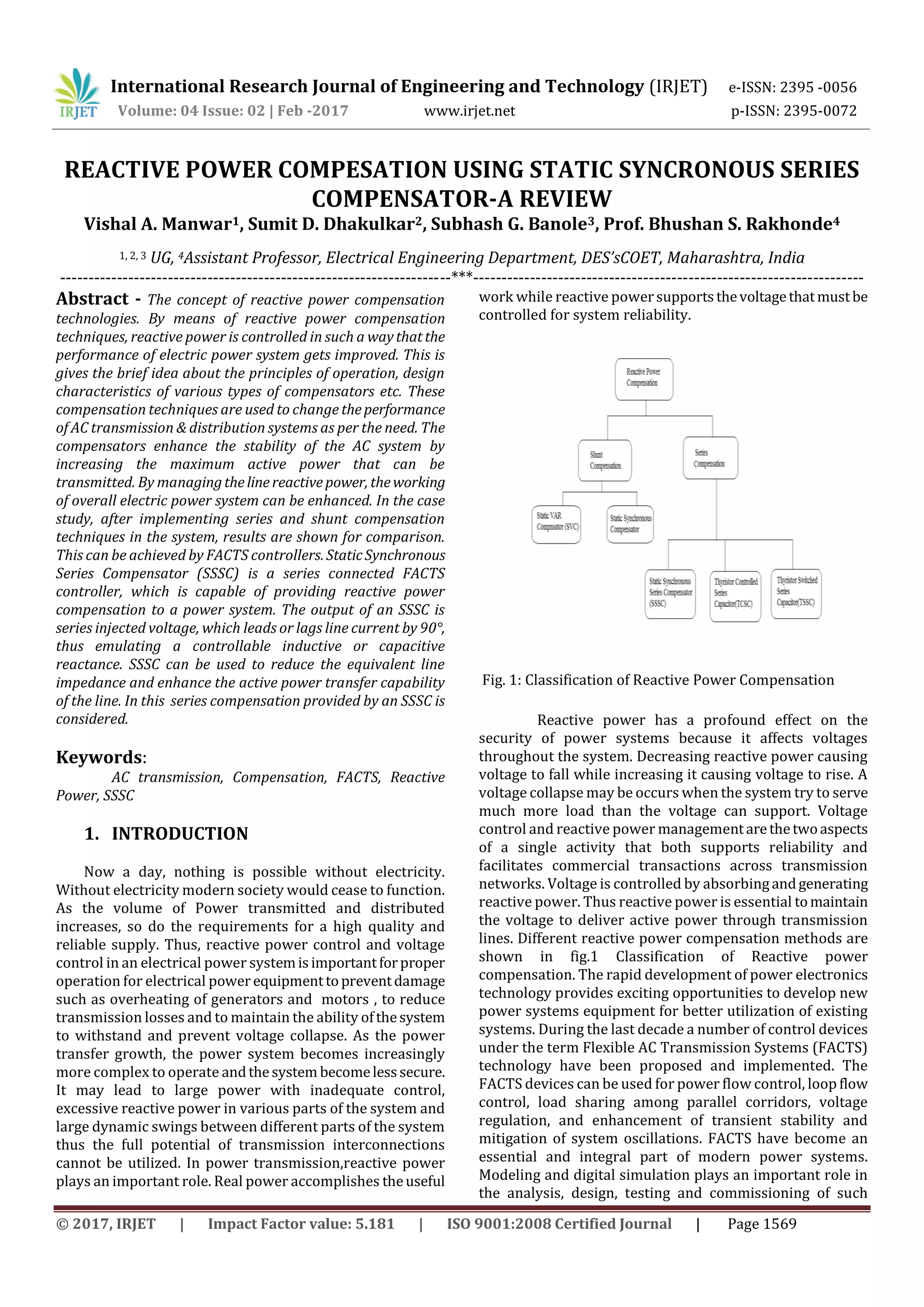
This document provides a review of reactive power compensation using static synchronous series compensators (SSSCs). It begins with an abstract discussing reactive power compensation techniques and FACTS controllers. It then reviews the principles and design of SSSCs. Key points made include: - SSSCs are series FACTS controllers that inject a controllable voltage in quadrature with the line current, emulating a variable inductive or capacitive reactance. This allows control of active and reactive power flow. - By reducing equivalent line impedance, SSSCs can enhance the active power transfer capability of transmission lines. Their control capabilities provide benefits like improved voltage stability and power oscillation damping. - The document evaluates SSSC