SlideShare a Scribd company logo
Beam Design


Beam Data
               width        200 mm
               depth        600 mm                                        d'      31 mm         .= cc+ sdia + mdia/2
 clear cover to main         15 mm                                 eff depth      569 mm        .= d - d'
                reinf.
Material Grades
           Concrete         20 MPa
               Steel        415 MPa

            Moment         153 KN-m                                 Mu/bd2          2.36
                                                                    xumax           273         .= (700/(1100 * (0.87 * fy)) * d
                                                                     Mulim          179         .= 0.36*fck*b*xumax*(d-(0.42*xumax))
                                                                  Mulim/bd2         2.76

Beam is designed as Singly Reinforced Beam


Area of Steel            Tension (Ast)    Compr (Asc)
Percentage               0.782 %          -------                       Refer Table 2 SP 16 pg 48
Area of Steel            890 sqmm


Tension Reinforcement
       Type           Bar dia                    Nos        Area of Steel
      Layer 1         16 mm                        2         402 sqmm
      Layer 2         20 mm                        2         628 sqmm
      Layer 3         20 mm                        2         628 sqmm
                                       Total Steel Provided 1659 sqmm                 1.458 %
                                       Provided Steel OK


Compression Reinforcement
     Type            Bar dia                        Nos       Area of Steel
    Layer 1          16 mm                           2
    Layer 2          12 mm                           2
    Layer 3
                                       Total Steel Provided                           0.000 %


Shear Force (Vu)         300 KN
ζv                       2.636            .=Vu / (b * d)
ζc                       0.817            Refer Table 61 SP 16 pg 179          or =(0.85*√(0.8*fck)*√(1+5β)-1)) / (6β)
ζcmax                    2.8              Refer Table J SP 16 pg 175


        Type                 Bar Dia             Nos        Area of Steel
       Layer 1               25 mm                 2         982 sqmm
       Layer 2               25 mm                 2         982 sqmm
       Layer 3               20 mm                 2         628 sqmm
                                       Total Steel Provided 2592 sqmm                 2.278 %

Sectional Dimensions OK
Shear Reinforcements required


Type of stirrup          2 legged
Stirrup diameter         8 mm
Spacing                  100 c/c
Steel Calculation


                                    Grade Check
                                        7.1

               SRB                                                   DRB
                 a        0.75     .=(0.87435/100) * (fy/fck)2          a              0.75      .=(0.87435/100) * (fy/fck)2
                 b      -3.611     .=(0.87/100) * (fy)                  b             -3.611     .=(0.87/100) * (fy)
                 c       2.363     .=Mu/bd2                             c              2.762     .=Mulim/bd2
                -p       0.782     .=-(b±√(b2-4ac))/2a                 -p              0.955     .=-(b±√(b2-4ac))/2a
               Ast        890      .=(p*b*d)/100                     Astlim            1087      .=(p*b*d)/100


                                                                       Mu2               -26     .=Mu - Mulim
                                                                       Ast2             -133     .=Mu2/((0.87*fy)*(d-d'))
                                                                       Ast               954     .=Astlim+Ast2

                                       0.0545                          d'/d             0.10
                                         0.1                           fsc               353     Refer Table F SP 16 pg 13
                                                                       fcc              8.92     .=0.466*fck
                                                                       Asc              -140     .=Mu2/((fsc-fcc)*(d-d'))

                                     Min steel %        0.205    .=0.85% / fy
                                         Ast             890
                                        Asc             -140

                                     Min Steel          233      .=(0.85*b*d) / fy
                                     Max Steel          4552     .=0.04*b*d)

                                         Ast             890
                                         Asc


Shear Calculations

                                    Pt provided         2.278    .=(Ast*100)/(b*d)
                                    Pc provided                  .=(Asc*100)/(b*d)
                                          β             1.020    .=(0.8*fck)/(6.89*Pt)


                     Shear Capacity of Concrete (Vs)             93             .=ζc*b*d
                     Shear Stg to be caried by Stirrup (Vus)     207            .=Vu-Vs

                     Spacing
                                                                                least of the 4
                                                                                 provide the


                      actual req         100       .=(Asv*0.87fy*d)/Vus
                         min             454       .=(Asv*0.87fy)/(b*0.4)
                         max             427       .=0.75d
                         max             300       .=300mm
Slab Design


Slab thickness t                           125 mm                                 Sunken Depth             325 mm
Concrete             fck                   20 MPa
Steel                fy                    415 MPa

Loading
Slab Load                                                                         Sunken Slab Load
Dead Load            DL                    3.125 KN/m                             Dead Load     DL         3.125 KN/m
Live Load            LL                    3.000 KN/m                             Filler Load   FL         5 KN/m
Finishes Load        WL                    1.000 KN/m                             Live Load     LL         3.0 KN/m
Total Load           Ws                  7.125 KN/m                               Finishes Load WL         1.0 KN/m
Factored Load        Wsu                 11 KN/m                                  Total Load    Wsk        11.74 KN/m
                                                                                  Factored Load Wsku       18 KN/m


Slab Data
       Slab Type           Regular
            Load           11 KN/m
 Longer Span (ly)           8.20 m                                                ly/lx ratio     2.05
 Shorter Span (lx)          4.00 m                                                Slab type        -


Loading on edges                            one way       two way
     Wlonger               21 KN/m          .=w*lx/2     .=(w*lx/2) + (1-(1/3)*(lx/ly)2)
     Wshorter                                            .=w*lx/3

Moments                                     one way        two way
        Mx                 21 KN-m         .=w*lx2/ 8    .=αx * w*lx2
                                                         .=αy * w*lx2

Thickness Check              OK          .=Mulim > Mux or Muy
Deflection                  10 mm        .= 5*W*l4/(384EI)


                            Astx                         Refer Chart 4 SP 16 pg 21                 or
  Area of Steel
                       647 sqmm                          Refer Table 5-44 SP 16 pg 51-80


Spacing required in mm
             8#                                    10#                             12#                     16#
       x              y                        x              y            x               y        x            x
     78 c/c                                 121 c/c                     175 c/c                  311 c/c
.=ast of bar*1000/ast req


    Final Ast                        x                                       y
    provided
Design Calculations

ONE WAY                                               TWO WAY
         a    0.75    .=(0.87435/100) * (fy/fck)
                                               2              a    0.75    .=(0.87435/100) * (fy/fck)2
         b   -3.611   .=(0.87/100) * (fy)                     b   -3.611   .=(0.87/100) * (fy)
        cx    1.939   .=Mu/bd2                               cy   0.000    .=Mu/bd2
       -px    0.616   .=-(b±√(b2-4ac))/2a                   -py   0.000    .=-(b±√(b2-4ac))/2a
       Ast     647    .=(p*b*d)/100                         Ast      0     .=(p*b*d)/100


 Min Ast       %        mm2
              0.12       150

                        Interpolation                                                                  1   0.06


                                                                             Table 26 IS 456 pg 91
   ly/lx                            αx                             αy                                1.1   0.06
  lower      upper      exact     lower       upper   interptn.
  value      value      value     value       value     value                                        1.2   0.07
   0.00       0.00      2.05      #N/A        #N/A      #N/A      0.06                               1.3   0.08
                                                                                                     1.4   0.09
                                                                                                     1.5   0.09
                                                                                                       2   0.11

   xumax    50   .= (700/(1100 * (0.87 * fy)) * d
   Mulim 30 KN-m .= 0.36*fck*b*xumax*(d-(0.42*xumax))
 Mulim/bd2 2.76
  Mux/bd 2
           1.94
  Muy/bd2  0.00

         E 2.24E+07
          I 1.63E-04 .= bd3/12
     Defln 9.79 .= 5*W*l4/(384EI)
Column Design


Design Loads
         Load        Pu         2000 KN
      Moment         Mu         20 KN-m

Column Data
         width        b         200 mm
         depth        d         200 mm
        length        l         3.00 meters

Grade
        Concrete     fck        20 MPa
           Steel      fy        415 MPa

    Pu/(fckbd)       2.50                        Minimum eccentricity
   Mu/(fckbd2)       0.01                        ex    1.27 mm          OK
           d'/d      0.05                        ey    1.27 mm          OK


Refer Chart 31 of SP 16, Page no: 116

    pt/fck           0.18

     pt                 3.60%
     Ast           1440 sqmm


Number of bars
    dia              nos        ast
    25 mm             4         1963 sqmm            ● ● ●         ● ● ●     4- 25#

    20 mm             4         1257 sqmm                                    4- 20#
    20 mm             4         1257 sqmm            ● ● ●         ● ● ●     4- 20#
     Total            12        4477 sqmm

                                 Steel provided OK
ACE GROUP ARCHITECTS (P) Ltd.
Architects & Consulting Engineers

Project :                                           GAT M2
Title :                                             7.2m lvl
Designer :                                          Fahim H. Bepari
Date :                                              18-Sep-2009


Slab thickness                                      t          150 mm
Concrete                                            fck        20 MPa
Steel                                               fy         415 MPa


Loading
Slab Load
Dead Load                                           DL         3.75 KN/m
Live Load                                           LL         2.00 KN/m
Garden Load                                         GL         7.20 KN/m
Water Proofing Load                                 WL         1.00 KN/m
Total Load                                          Ws         13.95 KN/m
Factored Load                                       Wsu        21 KN/m


Design & Reinforcement Details of Slabs

Slab Data                                                                                                                                                                           Spacing required in mm


                                                                                                                                                                                                                                                               Slab Name
                                                                            Slab type


                                                                                                                                                                                                                                                   Slab type
                                                                                                                                                                                                                             Spacing provided in
                                         Longer     Shorter                             Loading on edges           Moments         Thickness        Area of Steel
                                Load
                                         Span       Span         ly/lx                                                                                                         8#              10#                12#        mm c/c
Sl.No      Sl. Id   Thickness                                                                                                      Check
                              Wsu / Wsku     ly         lx                               Wlonger    Wshorter     Mx        My                    Astx          Asty     x           y      x         y        x         y        x        y

  1        Sunk     150 mm      21 KN     5.20 m      5.00 m     1.04
                                                                            +           36 KN/m    35 KN/m     31 KN-m   29 KN-m       OK      753 sqmm    706 sqmm   67 c/c    71 c/c   104 c/c 111 c/c 150 c/c 160 c/c
                                                                                                                                                                                                                                                   +
  2     Regular     150 mm      21 KN     5.20 m      2.50 m     2.08
                                                                            -           26 KN/m                16 KN-m                 OK      372 sqmm               135 c/c            211 c/c            304 c/c
                                                                                                                                                                                                                                                   -
  3     Regular     150 mm      21 KN     6.50 m      5.80 m     1.12
                                                                            +           45 KN/m    41 KN/m     46 KN-m   40 KN-m       OK      1231 sqmm 1005 sqmm    41 c/c    50 c/c   64 c/c    78 c/c   92 c/c 113 c/c
                                                                                                                                                                                                                                                   +
 3A     Regular     150 mm      21 KN     2.00 m      1.10 m     1.82
                                                                            +           10 KN/m    8 KN/m      3 KN-m    1 KN-m        OK      180 sqmm    180 sqmm   279 c/c 279 c/c 436 c/c 436 c/c 628 c/c 628 c/c
                                                                                                                                                                                                                                                   +
 3B     Regular     150 mm      21 KN     5.30 m      4.30 m     1.23
                                                                            +           35 KN/m    30 KN/m     29 KN-m   22 KN-m       OK      691 sqmm    504 sqmm   73 c/c 100 c/c 114 c/c 156 c/c 164 c/c 224 c/c
                                                                                                                                                                                                                                                   +
  4     Regular     150 mm      21 KN     35.00 m     2.60 m     13.46
                                                                            -           27 KN/m                18 KN-m                 OK      404 sqmm               124 c/c            194 c/c            280 c/c
                                                                                                                                                                                                                                                   -
  5     Regular     150 mm      21 KN     9.20 m      4.10 m     2.24
                                                                            -           43 KN/m                44 KN-m                 OK      1154 sqmm              44 c/c             68 c/c             98 c/c
                                                                                                                                                                                                                                                   -
  6     Regular     150 mm      21 KN     9.20 m      4.00 m     2.30
                                                                            -           42 KN/m                42 KN-m                 OK      1083 sqmm              46 c/c             73 c/c             104 c/c
                                                                                                                                                                                                                                                   -
  7     Regular     150 mm      21 KN     8.00 m      3.20 m     2.50
                                                                            -           34 KN/m                27 KN-m                 OK      638 sqmm               79 c/c             123 c/c            177 c/c
                                                                                                                                                                                                                                                   -
Project                       NCC
Date                          18-Sep-09

                                                        Grid Floor Analysis & Design


      Data                                x direction                                 y direction
                                                                                                                                       bf
      Length of beams                    Lx = 14.00 meters                              Ly = 14.00 meters
                                                                                                                   Df
      Number of beams                    Nx = 6 nos                                     Ny = 6 nos
      Spacing of ribs                    a1 = 2.00 meters                               b1 = 2.00 meters
      Depth of beam                      D = 900 mm                                                                                              D
      Width of beam                      bw = 200 mm
      Width of flange                    bf = 2000 mm
      Thickness of flange                Df = 150 mm
      Grade of Concrete                  fck = 20 MPa
                                                                                                                                       bw
      Grade of Steel                      fy = 415 MPa
                                                                                                                                            a1
      Modulas of Elasticity               E = 2.2E+07 KN/sqm

      Loads
      Live Load               3.00 KN
      Floor Finish            1.00 KN
      Other                   0.00 KN

      Loading Calculation
                                                                                                          Ly
      Total weight of slab                               ws = 735.00 KN
                                                         wbx = 378.00 KN                                                                         b1
      Total weight of beams in x direction
      Total weight of beams in y direction               wby = 345.60 KN
      Total weight of Live load                          wll = 588.00 KN
      Total weight of Floor Finish                        wff = 196.00 KN
      Other load                                         wol =
      Total Load                      ws+wbx+wby+wll+wff+wol = 2242.60 KN                                                         Lx
      Total Load/sqm                                       q = 11.44 KN/sqm
      Total Factored Load/sqm                             Q = 17.16 KN/sqm

      Design Parameters
                              Ratios
                                       Df/D = 0.167
                                       bf/bw = 10.000

                              Moment of Inertia
                                    I = (kx*bw*D3)/12
                                       kx = 2.3                             refer Chart 88 of SP 16 pg 215
                                      I = 2.79E-02

                              Flexural Rigidity of ribs
                                          Dx=EI/a1                                     Dy=EI/b1
                                       Dx = 3.12E+05                                Dy = 3.12E+05

                              Modulus of Shear
                              G=E / (2(1+μ)
                                   G = 9.72E+6 KN/sqm

                              Torsional Constants (Polar Sectional Modulus)
                                C1=(1-(0.63*(bw/D))*(bw3*D/3)     C2=(1-(0.63*(bw/D))*(D3*bw/3)
                                     C1 = 2.06E-3 cum                  C2 = 4.18E-2 cum

                              Torsional Rigidity
                                         Cx=GC1/b1                                   Cy=GC2/a1
                                       Cx = 1.00E+4                                 Cy = 2.03E+5

                                         2H=Cx+Cy
                                        2H = 2.13E+5

                                                          Dx / Lx4 = 8.13
                                                          Dy / Ly4 = 8.13
                                                   2H / (Lx2*Ly2) = 5.55

      Deflection Check
                              Central Deflection
                                           ω=(16*Q/π)/((Dx/Lx4)+(2H/(Lx2*Ly2))+(Dy/Ly4))
                                                         ω = 13.09 mm

                              Long Term Deflection
                                        Ltdefl. = 3*ω
                                     Ltdefl. = 39.28 mm


                                      span/deflection
                                    (Clause 23.2 IS 456)
                                       s/d = 56.00 mm

                              Maximum deflection including long term effects is within permissible limits i.e. Ltdefl < s/d ratio


      Maximum Moment & Shear Values

                              Max Bending Moments
                                          Mx=Dx*(π/Lx)2*ω                                  My=Dy*(π/Ly)2*ω
                                          Mx = 206 KN-m                                    My = 206 KN-m

                              Max Torsional Moments
                                          Mxy=(Cx*π2*ω1)/(Lx*Ly)
                                          Mxy = 7 KN-m

                              Shear Force
                                             Qx=[(Dx*(π/Lx)3)+(Cy*(π3/(a*b2)))]*ω          Qy=[(Dy*(π/Ly)3)+(Cx*(π3/(b*a2)))]*ω
                                             Qx = 48 KN                                    Qy = 48 KN
Staircase Design


Data
Effective Span (l)                         5.00 mm
Riser (R)                                  150 mm
Thread (T)                                 300 mm
Waist Slab thickness (t)                   150 mm
Clear Cover                                 15 mm
Effective Depth of Waist Slab (d)          135 mm

Grade of Concrete (fck)                     20 MPa
Grade of Steel (fy)                        415 MPa

Loading
Loads on going                                                   Loads on waist slab
Self weight of waist slab                  4.19 KN/m             Self weight of landing slab     3.75 KN/m
Self weight of steps                       1.88 KN/m             Live Load                       2.00 KN/m
Live Load                                  3.00 KN/m             Floor Finish Load               1.00 KN/m
Floor Finish Load                          1.00 KN/m                               Total Load    6.75 KN/m
                          Total Load      10.07 KN/m                          Factored Load     10.13 KN/m
                      Factored Load       15.10 KN/m


Bending Moment
     Calculate Bending Moment using the equation (W*L*L )/8                                                  ###
Bending Moment = 47 KN-m

Reaction
to be used as UDL = 38 KN                                                                                    ###
                                                                 60 KN-m

Area of Main Steel
                                    Ast    1184 sqmm

Spacing
                     Diameter of bar         12ø        16ø
                    Spacing across x        96 c/c     170 c/c

                 Provded Main Steel:


Area of Distribution Steel
                                    Ast     180 sqmm

Spacing
                     Diameter of bar          8ø        10ø
                    Spacing across y        279 c/c    436 c/c

          Provided Distridution Steel:
Seismic Zone                                       II            Table 2 IS 1893 2002 pg 16
Seismic Intensity                       z          0.1

Importance factor                       I          1.5           Table 6 IS 1893 2002 pg 18

Response Reduction Factor               R          3             Table 7 IS 1893 2002 pg 23

Lateral Dimension of Building           d          65.6          meters
Height of the of Building               h          50.4          meters

                                             with brick infill
Fundamental Natural Period              Ta        0.560

Type of Soil                            Medium Soil

Spectral Acceleration Coefficient       Sa/g       0.000

Design Horizontal Seismic Coefficient   Ah         0

Seismic Weight of Building              W          680034        KN

Design Seismic Base Shear               VB         0             KN
Date        18-Sep-09
Footing No. F2


     1     Footing Size Design


           Load 1                        Pu1            2000 KN
           Load 2                        Pu2            1850 KN
           Combine load                  Pcu            3850 KN
           Design Load                   Pc             2823 KN

           Moment in x dir               Mux            40 KN-m
           Moment in y dir               Muy            40 KN-m

           c/c dist b/w col in x dir                  2.725 meters
           c/c dist b/w col in y dir                  0.000 meters

           Col Dim                       x dir        0.20 meters
                                         y dir        0.20 meters

           SBC                            q            150 KNm2

           Footing Size required        A req         18.82 sqmm

                                          L          6.00 meters
           Footing Size Provided
                                          B          3.20 meters
           Area Provided                A prvd       19.20 meters

                                        x bar            1.309
                                        y bar            0.000

                                          Zx             10.24
                                          Zx             19.20

                                         Nup           151 KNm2

                                       Increase the Footing Size
2   Beam Design

    Total Load                     W           151 KNm2
    Factored Load                  Wu          725 KNm2

          1.691 meters                       2.725 meters                    1.584 meters


                                                                                             3.20 meters


                                               6.00 meters


                                                  725 KNm2


          1.69 meters                          2.73 meters                     1.58 meters


    Beam Size              width                 600 mm
                           depth                 900 mm

    Moment                 Mb                   898 KN-m

    Design the beam from the BEAM DESIGN SHEET

    Bottom Reinforcement
             Type               Bar dia           Nos        Area of Steel
            Layer 1             25 mm              6         2945 sqmm
            Layer 2             25 mm              6         2945 sqmm
            Layer 3                -
                                          Total Steel Provided 5890 sqmm
                                          Percentage of Steel   1.148 %

    Top Reinforcement
              Type              Bar dia           Nos        Area of Steel
            Layer 1             25 mm              6         2945 sqmm
            Layer 2             20 mm              6         1885 sqmm
            Layer 3                -
                                          Total Steel Provided 4830 sqmm
3   Slab Design


    Net upward pressure            Nup          151 KNm2
                                    l           1.30 meters                 /=width of footing from col face

    Bending Moment                 Ms            128 KN-m                   M=Nup*l2/2
    Factored Moment                Mus           191 KN-m                   1.5*Ms

    Concrete                        fck           20 MPa
    Steel                            fy           415 MPa

    Minimum Depth Required         dmin             264                     d=sqrt(Ms/Rumax*1000*b)

    Depth Provided                  D             600 mm
    Clear Cover                     c              50 mm
    Effective Cover                 d'             56 mm
    Effective Depth                 d'            544 mm

     Area of Steel across x dir             Spacing c/c in mm
                                   12#              16#          20#
            1014 sqmm             112 c/c          198 c/c      310 c/c


    Ast across x direction         12 mm dia @ 100 mm c/c       1131 sqmm
    Dist Ast across y direction     8 mm dia @ 175 mm c/c        287 sqmm


4   Shear Check for Slab

                                   Vu1             171 KN
                                    ζv           0.315 MPa

                                    ζc           0.316 MPa

                                     Shear Check OK
5
                                                          6.00 meters


3.20 meters                                                                                                600 mm


                       1.7 meters                      2.73 meters                     1.6 meters


                                                 600 mm


        6 - 25 mm dia
        6 - 20 mm dia                                                             6 - 25 mm dia
                                    900 mm


                                                                                  6 - 25 mm dia


                                                                                           600 mm
              250 mm


                                             8 mm dia @ 175 mm c/c                        12 mm dia @ 100 mm c/c


                                                                  6 - 25 mm dia
                                                                  6 - 20 mm dia


                                                                  6 - 25 mm dia
                                                                  6 - 25 mm dia
Design Of Isolated Footing                    15 of 37

1   Footing Size Design

    Load                          Pu             1500 KN
    Design Load                   P              1100 KN

    Moment in x dir              Mux             30 KN-m
    Moment in y dir              Muy             30 KN-m

    Column size                   cx             450 mm
                                  cy             450 mm

    SBC                            q           150 KN/sqm

    Footing Size required        A req          7.33 sqmm

                                  L            3.30 meters
      Footing Size Provided
                                  B            2.40 meters
    Area Provided               A prvd         7.92 meters

                                  Zx               3.17
                                  Zx               4.36

    Net upward pressure           Nup           150 KNm2

                                       Footing Size OK


2   Slab Design
                                   lx             1.425
                                   ly             0.975

    Bending Moment in x dir       Mx            228 KN-m
    Bending Moment in y dir       My            107 KN-m

    Concrete                      fck             20 MPa
    Steel                          fy            415 MPa

    Minimum Depth Required       dmin              288

    Depth Provided                 D             650 mm
    Clear Cover                    c              50 mm
    Effective Cover                d'             58 mm
    Effective Depth                d'            592 mm

                                           Spacing c/c in mm
          Area of Steel
                                 12#              16#           20#
           1111 sqmm            102 c/c          181 c/c       283 c/c
           710 sqmm             159 c/c          283 c/c       442 c/c

    Minimum Ast required across y direcion

    Ast across x direction      16 mm dia @ 125 mm c/c            1608 sqmm
    Ast across y direction      16 mm dia @ 125 mm c/c            1608 sqmm
Design Of Isolated Footing   16 of 37

3   One Way Shear along x direction

                                Vu1           449 KN
                                 ζv         0.316 MPa

                                 ζc         0.317 MPa
                                Vc1           451 KN

                              One Way Shear Check OK

4   One Way Shear along y direction

                                Vu1           284 KN
                                 ζv         0.145 MPa

                                 ζc         0.260 MPa
                                Vc1           508 KN

                              One Way Shear Check OK


5   Two Way Shear
                                Vu2          1536 KN
                                 ζv         0.622 MPa

                               ks*ζc        1.118 MPa
                                Vc1          2759 KN

                              Two Way Shear Check OK
Design Of Isolated Footing                   17 of 37

                        L= 3.30 meters


                               450


                         450
B= 2.40 meters


   250 mm                                       650 mm


                 16 mm dia @ 125 mm c/c       16 mm dia @ 125 mm c/c
Dimensions of Dome
Diameter        d=                       12600 mm
Height          h=                        3000 mm
Thickness       t=                        150 mm


Radius of Sphere r =                       8115 mm


                                                                                   h = 3.00 m
                 Φ=                    50.93
                 Ѳ=                    0 to 50.93


Loading                                                                                         d = 12.60 m
Dead Load           DL =                 3.75 KN/m
Live Load           LL =                 0.10 KN/m                                               50.93            r = 8.12 m
Wind Load           WL =                 0.10 KN/m
                                                                                                                                 0m
Total Load          W=                   3.95 KN/m                                                                   11   5. 0
Factored Load       Wu =                 5.93 KN/m                                                            r   =8

Meridional Stress                                                 Hoop Stress
                              Ѳ              Mt                                                    Ѳ                  Mt
                            50.93        0.197 MPa                                               50.93            0.003 MPa
                            45.00        0.188 MPa                                               45.00            0.025 MPa
                            40.00        0.182 MPa                                               40.00            0.041 MPa
                            35.00        0.176 MPa                                               35.00            0.055 MPa
                            30.00        0.172 MPa                                               30.00            0.067 MPa
                            25.00        0.168 MPa                                               25.00            0.077 MPa
                            20.00        0.165 MPa                                               20.00            0.086 MPa
                            15.00        0.163 MPa                                               15.00            0.093 MPa
                            5.00         0.161 MPa                                               5.00             0.100 MPa
                            0.00         0.160 MPa                                               0.00             0.101 MPa

Maximum Meridional Stress                0.197 MPa                Maximum Hoop Stress                             0.101 MPa


                                                          fck     20 MPa
                                                          Fy      415 MPa
                                                          бst     230.00

                       Area of steel        128 sqmm                                   Area of steel               66 sqmm

                           Bar Dia        10 mm                                                 Bar Dia            10 mm
                           Spacing        613 c/c                                               Spacing           1187 c/c


                    Meridional Thrust @ Base            29 KN/m
                    Horizontal Component on Ring Beam   19 KN/m
                    Hoop Tension on Ring Beam            117 KN

                       Area of steel        509 sqmm

                         Bar Dia           16 mm
                        No of Bars         3 nos
ACE GROUP ARCHITECTS (P) Ltd.
                                                                                                                 Architects & Consulting Engineers
Project :          MVJ
Block :            L-Block
Date :             18-Sep-2009
Designer :         Fahim H. Bepari

Design & Reinforcement Details of Columns

                                                                                                                           Design Constants            Design                                 Final   Ast                          Area of Steel
Sl Grid            Col    Col                                                                                                                        Paramenters                              Required
        Col Nos.                   Load          Moment                    Column Data                  Grade                                                            Ast Req     Remark                                                                                     Check     Fig
No. No             type   Shape                                                                                      Pu/(fckbdl) Mu/(fckbdl2) d'/d                                                                 Type 1                 Type 2        Total Reinf Provided
                                                                                                                                                                                   Ast less than                                                                                 Steel
 1    -       -     C1      R     1500 KN   30 KN-m   30 KN-m   200 mm 750 mm   750 mm 50 mm 3.60 m 20 MPa 415 MPa      0.50        0.01      0.1    0.02       0.40%   600 sqmm   min Ast req. 1200 sqmm   4   12 mm   452 sqmm   2   12 mm 226 sqmm    6     679 sqmm        provided
                                                                                                                                                                                                                                                                               NOT OK


      09/18/2009                                                                                                                                Page 19 of 37
19.7 KNm2

Dimensions of Dome
Diameter                 d=         12600 mm
Height                   h=         5000 mm


Radius of Sphere         r=           6469 mm
                         Φ=       76.87
                         Ѳ=       0 to 76.87


Loading
Dead Load               DL =        3.00 KN/m
Live Load               LL =        0.10 KN/m
Other Load              OL =       10.00 KN/m
Total Load              W=           13 KN/m
Factored Load           Wu =         20 KN/m


Vertical Reaction     VA = VB =     123.8 KN
Horizontal Reaction   HA = HB =     234.0 KN

                          Ѳ             x            y     Moment
                        76.87         0.00         0.00       0
                        75.00         0.05         0.21      -42
                        60.00         0.70         1.77     -331
                        50.00         1.34         2.69     -481
                        40.00         2.14         3.49     -596
                        30.00         3.07         4.13     -680
                        20.00         4.09         4.61     -737
                        10.00         5.18         4.90     -769
                         5.00         5.74         4.98     -777
                         0.00         6.30         5.00     -780

                                          Max Values      780 KN-m
h = 5.00 m


                d = 12.60 m

76.87                         r = 6.47 m
                                                  m
                                        9.   00
                                    646
                               r=


             Radial Shear     Normal Thrust             0    67   174
                  67              174                  42    59   180
                  59              180                 331    10   224
                 -10              224                 481    56   245
                 -56              245                 596   100   259
                -100              259                 680   141   265
                -141              265                 737   178   262
                -178              262                 769   209   252
                -209              252                 777   222   244
                -222              244                 780   234   234
                -234              234

               234 KN            265 KN
ACE GROUP ARCHITECTS (P) Ltd.
                                 Architects & Consulting Engineers

Project :       Jnana Vikas
Title :         Terrace Floor
Designer :      Fahim H. Bepari
Date :          18-Sep-2009

Beam :          CB11

Dimensions of Ring Beam
Radius                  r=              6.30 mts
No of supports         n=                 8 nos


Constants                Ѳ=              23 deg      0.3927 radians
                         Φm =             9 1/2      0.1658 radians

                         C1 =             0.07
                         C2 =             0.03
                         C3 =             0.01

Loading
                        Wu =            10 KN/m


                                           FΦ             MΦ            Mmt
                          Φ            Shear Force     Bending        Torsional
                                                       Moment         Moment
                         deg               KN           KN-m            KN-m
                         0               24.74         -20.62           0.00
                        9 1/2            14.29          -0.05           1.57
                        22 1/2            0.00          10.39           0.00


Beam Data
                        width            300 mm
                        depth            600 mm

Equivalent Shear
                   Ve = V+1.6(T/b) =     33 KN                             T=MΦ


Equivalent Moment
               Mt = T((1+D/b)/1.7) =     1 KN-m                          Mt = BM due to torsion
               Me1 = M+Mt =             22 KN-m             Me1 = Equivalent BM on tension side
               Me2 = M-Mt =             20 KN-m        Me2 = Equivalent BM on compression side
A                              Load                         2700
               Moment          x-dir               y-dir
               Bottom                  0                29
               Top                     6               137

                               Col Type            Rectangular Column (reinf. on 2 sides)

                                                   x-dir          y-dir
               Unsupported Length                           8250           8250
               Col Size                                      200            900
                             d'/D                            0.05           0.20
                             d'                                 40


                               Concrete                       20
                               Steel                         415

D


    Effective Length Ratio
                                    0.80      from IS Code
                                    0.90      manual Calculation
    Effective Length to be considered from                Manual Calculation
    Effective Length (le)       lex           Ley
                                         7425        7425
E   Slenderness Ratio
    le/D                      8       Short Column
    le/b                     37      Slender Column
    Moment due to Slen          Muax                    0
                                Muay                  372

    Min Ecc  ex                             46.5
             ey                             23.2
    Moment due to ecc          Mux                         125.55
                               Muy                          62.55


G   Reduction of Moments
    Percentage assumed                                       2.18
                               Asc                          3924

                               Puz                          2841

                                      k1               K2             Pb
               x-x                   0.22              0.1            367
               y-y                   0.18             -0.02           291

               Kx                    0.06
               Ky                    0.06

    Additional Moments due to ecc                  Max                    0
                                                   May                    21


    Modified Initial Moments   Mux                            3.6
                               Muy                           70.6


    Summary of Moments
    A        Moment due to eccentricity + Modified additional moments
             Mux                       126
             Muy                        83

    B          Modified initial moments + Modified additional moments
               Mux                         4
               Muy                        91

    C          0.4Muz + Modified additional moments
               Mux                         0
               Muy                        32


    Final Design Loads
               Pu                          2700
               Mux                          126
               Muy                           91
Project :          Delhi Public School
Block :            Indoor Sports Block
Date :             18-Sep-2009
Designer :         Fahim H. Bepari
Column :           C6a

         Design Loads
           Pu = 2400 KN
          Mux = 192 KN-m
          Muy = 517 KN-m

              Col Data
                b = 600 mm
                D = 750 mm
                d' = 40.0 mm
             d'/D = 0.10
             d'/b = 0.10

        Material Grades
           fck = 20 MPa
            fy = 415 MPa

       Design Constants
    Steel % pt = 1.2                       Ast = 5400 sqmm
         pt/fck = 0.06                   Min Ast = 3600 sqmm
   Pu/fck*b*D = 0.27
 Mux/fck*b*D2 = 0.11
  Muy/fck*b*D2 = 0.11

             Puz = 5682
             Mux1 = 743
             Muy1 = 594

       Pu/Puz = 0.42
      Mux/Mux1 = 0.26
      Muy/Muy1 = 0.87
               αn = 1.37

(Mux/Mux1)αn + (Muy/Muy1)αn               0.98

               Steel Percentage OK

                            Steel Details
                           nos             dia         ast
     Type 1                 4            20 mm     1257 sqmm
     Type 2                 8            16 mm     1608 sqmm
   Total Steel             12               -      2865 sqmm
   Percentage      0.64%
Simply supported beam   Simply supported beam
                             with UDL                with Point Load
Load                       W 30 KN/m                 10 KN/m
Length                     l 5.60 m                  5.00 m
Elasticity of Concrete
                           Ec 22000000 MPa           22000000 MPa
= 5000(√fck)
Width                      b    0.20 m               0.20 m
Depth                      d    0.45 m               0.60 m
Moment                     M    126.42 m             40.63 m
Reaction                   R    90.30 m              32.50 m
Moment of Inertia      =
                           Ixx 0.0015 mm4            0.0036 mm4
bd3/12
Deflection                      11.5 mm              0.3 mm
                           dy
Formula                         5Wl4/384EI           Wl3/48EI
Cantilever beam   Cantilever beam
with UDL          with Point Load
1400 KN/m         10 KN/m
3.80 m            5.00 m
22000000 MPa      22000000 MPa
1.50 m            0.20 m
1.10 m            0.60 m
2601.46 m         40.63 m
2738.38 m         32.50 m
0.1664 mm4        0.0036 mm4
10.0 mm           5.3 mm
Wl4/8EI           Wl3/3EI
125 mm                                   150 mm                                   175 mm                                   200 mm
Span
       Moment            Ast                    Moment            Ast                    Moment            Ast                    Moment            Ast
              Mu/bd2              Spacing              Mu/bd2              Spacing              Mu/bd2              Spacing              Mu/bd2              Spacing
       (KNm)            (mm2)                   (KNm)            (mm2)                   (KNm)            (mm2)                   (KNm)            (mm2)

                                12# @ 243 c/c                            12# @ 293 c/c                            12# @ 336 c/c                            12# @ 306 c/c
 3       16    1.45      465                      17    1.01      386                      18    0.75      337                      19    0.59      369
                                16# @ 432 c/c                            16# @ 521 c/c                            16# @ 597 c/c                            16# @ 546 c/c

                                12# @ 169 c/c                            12# @ 211 c/c                            12# @ 253 c/c                            12# @ 269 c/c
3.5      22     2        669                      23    1.36      536                      25    1.04      447                      26     0.8      421
                                16# @ 301 c/c                            16# @ 375 c/c                            16# @ 450 c/c                            16# @ 479 c/c

                                12# @ 126 c/c                            12# @ 156 c/c                            12# @ 181 c/c                            12# @ 202 c/c
 4       28    2.54      899                      30    1.78      723                      32    1.33      624                      34    1.05      559
                                16# @ 224 c/c                            16# @ 278 c/c                            16# @ 322 c/c                            16# @ 360 c/c

                                                                         12# @ 118 c/c                            12# @ 137 c/c                            12# @ 153 c/c
4.5                                               38    2.25      956                      41    1.71      824                      44    1.36      741
                                                                         16# @ 210 c/c                            16# @ 244 c/c                            16# @ 271 c/c

                                                                                                                  12# @ 109 c/c                            12# @ 121 c/c
 5                                                                                         50    2.08      1039                     54    1.67      931
                                                                                                                  16# @ 194 c/c                            16# @ 216 c/c

                                                                                                                  12# @ 85 c/c                             12# @ 98 c/c
5.5                                                                                        61    2.54      1327                     65    2.01      1155
                                                                                                                  16# @ 152 c/c                            16# @ 174 c/c

                                                                                                                                                           12# @ 80 c/c
 6                                                                                                                                  77    2.38      1418
                                                                                                                                                           16# @ 142 c/c
Span      150 mm         175 mm        200 mm

        12# @ 293 c/c 12# @ 336 c/c 12# @ 306 c/c
   3
        16# @ 521 c/c 16# @ 597 c/c 16# @ 546 c/c

        12# @ 211 c/c 12# @ 253 c/c 12# @ 269 c/c
  3.5
        16# @ 375 c/c 16# @ 450 c/c 16# @ 479 c/c

        12# @ 156 c/c 12# @ 181 c/c 12# @ 202 c/c
   4
        16# @ 278 c/c 16# @ 322 c/c 16# @ 360 c/c

        12# @ 118 c/c 12# @ 137 c/c 12# @ 153 c/c
  4.5
        16# @ 210 c/c 16# @ 244 c/c 16# @ 271 c/c

                      12# @ 109 c/c 12# @ 121 c/c
   5
                      16# @ 194 c/c 16# @ 216 c/c

                      12# @ 85 c/c   12# @ 98 c/c
  5.5
                      16# @ 152 c/c 16# @ 174 c/c

                                     12# @ 80 c/c
   6
                                     16# @ 142 c/c
DESIGN OF RETAINING WALL


1   Preliminary Data
       i) Height of RW                                                               h                    3.00 meters
      ii) Soil Density                                                               γs                   18 KN/cum
     iii) SBC                                                                        qo                   250 KN/sqm
                                                                                                          30 degrees
     iv) Angle of repose                                                             Ø
                                                                                                         0.524 radians
                                                                                                           0 degrees
     v) Surcharge Angle                                                              Ө
                                                                                                         0.000 radians
     vi) Coefficient of friction                                                    µ                         0.5
     vii) Surcharge Load                                                            Ws                     4 KN/sqm


2   Pressure Coefficients
         Active Pressure Coefficients
      i) =(cosӨ-√(cos2Ө-cos2Ø)*cosӨ) / (cosӨ+√(cos2Ө-                               Ca                       0.333
         cos2Ø))
         Passive Pressure Coefficients
     ii)                                                                            Cp                        3.00
          = (1+SinØ) / (1+SinØ)


3   Preliminary Dimensions
                                                                                                                                  Proposed         Adopted
      i)  Thickness of Stem                                               ts                                                          -          0.20 meters
     ii)  Thickness of footing base slab                                  tb = 0.08 * (h + hs)                                0.24 meters        0.30 meters
          Length of base slab                                             L = 1.5 * √(Ca/3) * (h + hs)                        1.61 meters
     iii)                                                                                                                                        2.00 meters
          or                                                              L = 0.6h to 0.65h                                   2.09 meters

     iv) Extra Height of Retaining Wall due to Surcharge                                                             hs = Ws/γs                  0.22 meters
      v) Total Height of Retaining Wall due to Surcharge                                                             Hs = h+hs                   3.22 meters

     vi) Extra Height of RW due to inclined back fill                                                           hi = (L-ts)* tanӨ                0.00 meters
     vii) Total Height of RW due to inclined back fill                                                              Hi = h+hi                    3.00 meters

    viii) Design Height of RW considered H = Max of H1 & H2                                                                                      3.22 meters


4   Stability against Overturning
       i) Active pressure due Surcharge Load                                                        Pa1 = Ca*Ws*h                                   4 KN
      ii) Active pressure due Backfill Load                                                         Pa2 = Ca*γs*h2 / 2                             27 KN
     iii) Total Load on stem                                                                        Pa = Pa1 + Pa2                                 31 KN

     iv)    Overturning Moment                                                           Mo= (Pa1 * h/2) +(( Pa2*CosӨ)* h/3)                      33 KNm


     v)                                           Load                                                   Lever arm from end of stem               Moment
     W1     Backfill Load                      = (L-ts)*(h-tb)*γs                 87 KN             (L-ts) / 2                0.90 meters          79 KNm
     W2     Surcharge Load                     = Ca*Ws*h                           4 KN             (L-ts) / 2                0.90 meters          4 KNm
     W3     Inclined Backfill Load             = ((L-ts)*hi)/2*γs                  0 KN             (L-ts) / 3                0.60 meters          0 KNm
     W4     Stem self weight                   = ts*(h-tb)*γconc                  14 KN             (L- (ts/2))/2             0.95 meters          13 KNm
     W5     Base self weight                   = L*tb*γconc                       15 KN             L/2                       1.00 meters          15 KNm
     W6     Downward component                 = Pa*sinӨ                           0 KN                                                            0 KNm
     W6     Other Load                                                                                                                             0 KNm
                                                                     ∑W           120 KN                                                   ∑Mw    110 KNm

     vi) Distance of Resultant Vertical Force from end of heel                                                                xw=∑Mw/∑W          0.92 meters

     vii) Stabilizing Moment                                                                                   Mr =∑W * (L - xw)                  130 KNm

    viii) Factor of Safety against OVERTURNING
          (FS)OT = 0.9 * (Mr/Mo)                                    3.54 > 1.4                                       Safe against Overturning


5   Stability against Sliding
      i) Sliding Force                                                                                      Pa*CosӨ                31 KN
     ii) Resisting Force                                                                                    F = µ*∑W               60 KN

     iii)   Factor of Safety against SLIDING
            (FS)SL=0.9*(F/(Pa*CosӨ))                                1.74 > 1.4                               Safe against Sliding

                                                         Shear Key not required

     iv) Shear key Design
                                                                      x                                   0.00 meters
     a) Shear Key Size
                                                                       y                                  0.00 meters
     b)     Distance from stem                                         z                                  0.00 meters
     c)     Heigth of exacavation                                     h1                                  0.00 meters
     d)     Heigth of exacavation                          h2 = h1 + y + (z * tanØ)                       0.00 meters
     e)     Passive Pressure                               Pp = Cp*γs*(h12-h22) / 2                          0 KN

     v) Revised Factor of Safety against SLIDING
        (FS)sliding = 0.9 * ((F+Pp)/(Pa*CosӨ))                                                 1.74 > 1.4
                                               Safe against Sliding


6   Soil Pressures at footing base
       i) Resultant Vertical Reaction                          ∑W = R                                       120 KN
      ii) Distance of R from heel                         Lr = (Mw+Mo)/R                                  1.19 meters
     iii) Eccentricity                                       e = Lr- L/2                                  0.19 meters
                           Eccentricity lies within middle third of the base hence OK

     iv) Pressure Distridution on soil         qmax = R/L * (1+(6*e/L))                                   95 KN/sqm
                                          qmin = R/L * (1-(6*e/L))                                        25 KN/sqm
                            Max Pressure qmax<SBC hence pressure on base is OK

            Pressure at junction of stem and q =q -((q -q )/L)*t )
     v)                                                                                                   88 KN/sqm
            heel                              sh max  max min   s
DESIGN OF L Shaped Cantilever RETAINING WALL


1   Preliminary Data
      i) Height of Retaining Wall                              h                             3.00 meters
      ii) Soil Density                                         γs                            18 KN/cum
     iii) SBC                                                  qo                            250 KN/sqm
     iv) Angle of repose                                        Ø                            30 degrees
                                                                                            0.524 radians
      v) Surcharge Angle                                        Ө                             0 degrees
                                                                                            0.000 radians
     vi) Coefficient of friction                               µ                                 0.5
     vii) Surcharge Load                                       Ws                             4 KN/sqm


2   Pressure Coefficients
      i) Active Pressure Coefficients                                                             Ca                         0.333
          =(cosӨ-√(cos2Ө-cos2Ø)*cosӨ) /
         (cosӨ+√(cos2Ө-cos2Ø))
     ii) Passive Pressure Coefficients                                                            Cp                         3.00
          = (1+SinØ) / (1+SinØ)


3   Preliminary Dimensions
                                                                                                                           Proposed               Adopted
       i) Thickness of Stem                                                        ts                                     min 200mm             0.20 meters
      ii) Thickness of footing base slab                                           tb = 0.08 * (h + hs)                   0.24 meters           0.30 meters
      iii) Length of base slab                                                     L = 1.5 * √(Ca/3) * (h + hs)           1.61 meters           2.20 meters
                                                                                   L = 0.6h to 0.65h                      2.09 meters

      iv) Extra Height of Retaining Wall due to Surcharge                          hs = Ws/γs                             0.22 meters
      v) Total Height of Retaining Wall due to Surcharge                           Hs = h+hs                              3.22 meters

     vi) Extra Height of RW due to inclined back fill                              hi = (L-ts)* tanӨ                      0.00 meters
     vii) Total Height of RW due to inclined back fill                             Hi = h+hi                              3.00 meters

     viii) Design Height of RW considered H = Max of H1 & H2                                                              3.22 meters


4   Stability against Overturning
      i) Active pressure due Surcharge Load                                        PHS = Ca*Ws*h                             4 KN
      ii) Active pressure due Backfill Load                                        PH = Ca*γs*h2 / 2                        31 KN
     iii) Total Load on stem (Force)                                               Pa = PHS + PH                            35 KN
     iv) Overturning Moment due to Imposed load                                    MOIL = PHS*h/2                            7 KN
     v) Overturning Moment due to Backfill load                                    MODL = PH*h/3                            33 KN
     vi) Overturning Moment                                                        Mo = (1.2*MDIL) + (1.4*MOIL)             50 KN


     v)                     Load                                                                                             Lever arm at end of stem          Moment
     W1     Backfill Load                       = (L-ts)*(h-tb)*γs                              105 KN            ((L-ts) / 2) + ts              1.20 meters   126 KNm
     W2     Inclined Backfill Load              = ((L-ts)*hi)/2*γs                               0 KN             ((L-ts) / 3) + ts              0.87 meters     0 KNm
     W3     Stem self weight                    = ts*(h-tb)*γconc                                15 KN            ts / 2                         0.10 meters     1 KNm
     W4     Base self weight                    = L*tb*γconc                                     17 KN            L/2                           1.10 meters     18 KNm
       ∑W                                                                                       136 KN                                   ∑Mw                   146 KNm

    viii)   Mw not less than (1.2*MODL) +(1.4*MOIL)                                                               Safe against Overturning
            -clause 20.1 page 33 of IS 456 2000


5   Stability against Sliding
      i) Sliding Force                                                                                                   Pa = PHS + PH               35 KN
     ii) Resisting Force                                                                                                  F = µ*∑W                   68 KN

     iii)   (FS)SL= (0.9*F)/(Pa)                                               1.73 > 1.4                            Safe against Sliding
             -clause 20.2 page 33 of IS 456 2000


6   Soil Pressures at footing base
      i) Net Moment at toe                   Mn = Mw - Mo                          105 KN
     ii) Point of application of Resultant R x = Mn/W                            0.77 meters
     iii) Eccentricity                       e = (L/2) - x                       0.33 meters                                             L/6= 0.37
                     e<L6 Eccentricity lies within middle third of the base hence OK

      iv) Pressure Distridution on soil         qmax = W/L * (1+(6*e/L))   117 KN/sqm
                                           qmin = W/L * (1-(6*e/L))          7 KN/sqm
                          Max Pressure qmax<SBC hence pressure on base is OK

            Pressure at junction of stem and    qsh=qmax-((qmax-qmin)/L)*ts)
      v)                                                                                     107 KN/sqm
            heel
7   Constants for Working Stress Method

    Design Constants
     i) Grade of concrete                                      20 MPa
     ii) Grade of steel                                       415 MPa

     iii)   Compr stress in concrete               c                                        7.0        table 21 page 81 IS 456
    iv)     Tensile stress in steel                t                                        230
     v)     Modular ratio                          m = 280/3c                              13.33
    vi)     Neutral axis depth factor              k=mc/(mc+t)                             0.289
    vii)    Lever arm                              j = 1 - k/3                             0.904
    viii)   Factor                                 R= cjk / 2                              0.913


8   Design

     A) Stem
     i) Beanding Moment at base of stem M = MODL + MOIL                                   40 KN/m

     ii) Thickness required                       dreq=√(Ms/(R*b)                        0.01 meters
     iii) Thickness provided                      ts                                     0.20 meters
                                              Thickness of Stem is OK

     iv) Ast required                              Ast = M/(t*j*tse)                                                1387 sqmm
     v) Ast provided                                                   16 mm dia @ 125 mm c/c                       1608 sqmm
     vi) Percentage of Steel                       pt = Ast/(b*d)                                                     0.99 %
                                                                       Steel OK

     B) Base Slab
        Force                                                                                                   Lever arm from end of stem             Moment
     i) Force due to backfill+surcharge             = (H2-tb)*(L-ts)*γs                     105        (L-ts) / 2                   1.00 meters        105 KNm
     ii)    Force due to inclined backfill          = hi/2*(L-ts)*γs                            0      (L-ts) / 3                        0.67 meters    0 KNm
     iii) Self Weight of base slab                  =L *tb*γconc                            17         L/2                               1.10 meters    18 KNm
                                                                           ∑Ws              122                                              Md        123 KNm
     vi) Upward soil pressure                     Nup = ((qsh+qmin)/2)*(L-ts)               114          ((qsh+(2*qmin))/(qsh+qmin)) /   1.59 meters   181 KNm
                                             Downward Pressure is greater                                         ((L-ts)/3)                 Mu        181 KNm

     v) Bending Moment                             Msh = Mu-Md                               58

     vi) Thickness required                        dreq=√(Ms/(R*b)                       0.25 meters   Thickness of Stem is OK
     vii) Thickness provided                       ts                                    0.30 meters

    viii) Ast required                                     Ast = M/(t*j*tse)                                        1157 sqmm
    ix) Ast provided                                                   16 mm dia @ 150 mm c/c                       1340 sqmm
     x) Percentage of Steel                                 pt = Ast/(b*d)                                            0.48 %
                                                                        Steel OK


     C) Reinforcement Details


                                                                                  FILL
DESIGN OF Reverse L Shaped Cantilever RETAINING WALL


1   Preliminary Data
      i) Height of Retaining Wall                              h                                   3.00 meters
      ii) Height of Plinth Fill                                hp                                  0.50 meters
     iii) Soil Density                                         γs                                  18 KN/cum
     iv) SBC                                                   qo                                  250 KN/sqm
          Angle of repose                                       Ø                                  30 degrees
     v)
                                                                                                  0.524 radians
            Surcharge Angle                                     Ө                                   0 degrees
      vi)
                                                                                                  0.000 radians
     vii) Coefficient of friction                              µ                                       0.5
     vii) Surcharge Load                                       Ws                                   4 KN/sqm


2   Pressure Coefficients
      i) Active Pressure Coefficients                                                                     Ca                          0.333
          =(cosӨ-√(cos2Ө-cos2Ø)*cosӨ) /
         (cosӨ+√(cos2Ө-cos2Ø))
     ii) Passive Pressure Coefficients                                                                    Cp                          3.000
          = (1+SinØ) / (1+SinØ)


3   Preliminary Dimensions
                                                                                                                                    Proposed               Adopted
       i) Thickness of Stem                                                          ts                                            min 200mm             0.20 meters
      ii) Thickness of footing base slab                                             tb = 0.08 * (h + hs)                         0.24 meters            0.45 meters
      iii) Length of base slab                                                       α = 1 - (q0/2.7*γs*H)                        -0.60 meters
                                                       if sloped backfill
                                                                                     L = H*sqrt((Ca*cosβ)/((1-α)*(1+3α))          0.00 meters
                                                                                     α = 1 - (q0/2.2*γs*H)                        -0.96 meters           2.45 meters
                                                      if horizontal backfill
                                                                                     L = 0.95*H*sqrt((Ca)/((1-α)*(1+3α))          0.00 meters
                                                                                     L = 0.6h to 0.65h                            2.09 meters

      iv) Extra Height of Retaining Wall due to Surcharge                            hs = Ws/γs                                    0.22 meters
      v) Total Height of Retaining Wall due to Surcharge                             Hs = h+hs                                     3.22 meters

     vi) Extra Height of RW due to inclined back fill                                hi = (L-ts)* tanӨ                             0.00 meters
     vii) Total Height of RW due to inclined back fill                               Hi = h+hi                                     3.00 meters

     viii) Design Height of RW considered H = Max of H1 & H2                                                                       3.22 meters


4   Stability against Overturning
      i) Active pressure due Surcharge Load                                          PHS = Ca*Ws*h                                    4 KN
      ii) Active pressure due Backfill Load                                          PH = Ca*γs*h2 / 2                                31 KN
     iii) Total Load on stem (Force)                                                 Pa = PHS + PH                                    35 KN
     iv) Overturning Moment due to Imposed load                                      MOIL = PHS*h/2                                   7 KN
     v) Overturning Moment due to Backfill load                                      MODL = PH*h/3                                    33 KN
     vi) Overturning Moment                                                          Mo = (1.2*MDIL) + (1.4*MOIL)                     50 KN


     v)                     Load                                                                                                      Lever arm at start of heel          Moment
     W1     Front fill Load                     = (L-ts)*(hp-tb)*γs                                       2 KN             ((L-ts) / 2)                    1.13 meters    2 KNm
     W3     Stem self weight                    = ts*(h-tb)*γconc                                        14 KN             (ts/2) + (L-ts)                 2.35 meters    33 KNm
     W4     Base self weight                    = L*tb*γconc                                             28 KN             L/2                           1.23 meters      34 KNm
     W5     Other Load                          PT Beam Load                                              0 KN
                                                                                ∑W                       43 KN                                                      ∑Mw   69 KNm

    viii)   Mw not less than (1.2*MODL) +(1.4*MOIL)                                                                        Safe against Overturning
            -clause 20.1 page 33 of IS 456 2000


5   Stability against Sliding
      i) Sliding Force                                                                                                            Pa = PHS + PH             35 KN
     ii) Resisting Force                                                                                                           F = µ*∑W                 22 KN

     iii)   (FS)SL= (0.9*F)/(Pa)                                               0.55 < 1.4                                   Unsafe against Sliding
             -clause 20.2 page 33 of IS 456 2000

    5a      Shear key Design
                                                                                    x                                              0.30 meters
      a) Shear Key Size
                                                                                     y                                             0.30 meters
      b)    Distance from stem                                                       z                                             0.30 meters
      c)    Heigth of exacavation                                                   h1                                             0.60 meters
      d)    Heigth of earth mobilization                                 h2 = h1 + y + (z * tanØ)                                  1.07 meters
      e)    Passive Pressure                                             Pp = Cp*γs*(h12-h22) / 2                                     21 KN

      v) Revised Factor of Safety against SLIDING
         (FS)sliding = 0.9 * ((F+Pp)/(Pa*CosӨ))                                                                      1.09 > 1.4
                                                 Unsafe against Sliding. Shear Key Required


6   Soil Pressures at footing base
i) Net Moment at toe                   Mn = Mw - (MOIL+MODL)                     28 KN
ii) Point of application of Resultant R x = Mn/W                               0.65 meters
iii) Eccentricity                       e = (L/2) - x                          0.58 meters      L/6= 0.41
      e>L6 Eccentricity lies outside the middle third of the base. Revise the base dimensions

iv) Pressure Distridution on soil       qmax = W/L * (1+(6*e/L))        43 KN/sqm
                                     qmin = W/L * (1-(6*e/L))           -7 KN/sqm
                      Max Pressure qmax<SBC hence pressure on base is OK

     Pressure at junction of stem and   qsh=qmax-((qmax-qmin)/L)*ts)
v)                                                                           39 KN/sqm
     heel
7   Constants for Working Stress Method

    Design Constants
     i) Grade of concrete                             20 MPa
     ii) Grade of steel                               415 MPa

     iii)   Compr stress in concrete       c                                             7.0            table 21 page 81 IS 456
    iv)     Tensile stress in steel        t                                             230
     v)     Modular ratio                  m = 280/3c                                   13.33
    vi)     Neutral axis depth factor      k=mc/(mc+t)                                  0.289
    vii)    Lever arm                      j = 1 - k/3                                  0.904
    viii)   Factor                         R= cjk / 2                                   0.913


8   Design

     A) Stem
     i) Beanding Moment at base of stem M = MODL + MOIL                             40 KN/m

     ii) Thickness required                dreq=√(Ms/(R*b)                         0.01 meters
     iii) Thickness provided               ts                                      0.20 meters
                                          Thickness of Stem is OK

     iv) Ast required                      Ast = M/(t*j*tse)                                                    1387 sqmm
     v) Ast provided                                           16 mm dia @ 120 mm c/c                           1676 sqmm
     vi) Percentage of Steel               pt = Ast/(b*d)                                                         0.99 %
                                                                  Steel OK

     B) Base Slab
        Force                                                                                                    Lever arm from end of stem            Moment
     i) Force due to Frontfill              = (L-ts)*(hp-tb)*γs                          2              (L-ts) / 2                   1.13 meters       2 KNm
     iii) Self Weight of base slab          = L* tb * γconc                              28             L/2                              1.23 meters   34 KNm
    ∑Ws                                                                                  30                                                  Md        36 KNm
     vi) Upward soil pressure              Nup = ((qsh+qmin)/2)*(L-ts)                   35              ((qsh+(2*qmin))/(qsh+qmin)) /   1.03 meters   36 KNm
                                        Upward Pressure is greater                                                ((L-ts)/3)                 Mu        36 KNm

     v) Bending Moment                     Msh = Mu-Md                                   0

     vi) Thickness required                dreq=√(Ms/(R*b)                         0.01 meters          Thickness of Stem is OK
     vii) Thickness provided               ts                                      0.45 meters

    viii) Ast required                             Ast = M/(t*j*tse)                                              2 sqmm
    ix) Ast provided                                           12 mm dia @ 150 mm c/c                            754 sqmm
     x) Percentage of Steel                         pt = Ast/(b*d)                                                0.00 %
                                                                    Steel OK


     C) Reinforcement Details


                                                                                                 FILL
Rcc Design Sheets
Rcc Design Sheets
Rcc Design Sheets

More Related Content

What's hot

BIAXIAL COLUMN DESIGN
BIAXIAL COLUMN DESIGNBIAXIAL COLUMN DESIGN
BIAXIAL COLUMN DESIGN
shawon_sb
 
Rcc member design steps
Rcc member design stepsRcc member design steps
Rcc member design steps
DYPCET
 
Design of columns biaxial bending as per IS 456-2000
Design of columns  biaxial bending as per IS 456-2000Design of columns  biaxial bending as per IS 456-2000
Design of columns biaxial bending as per IS 456-2000
PraveenKumar Shanmugam
 
Deflection & cracking of RC structure(limit state method)
Deflection & cracking of RC structure(limit state method)Deflection & cracking of RC structure(limit state method)
Deflection & cracking of RC structure(limit state method)
gudtik
 
Design of columns as per IS 456-2000
Design of columns as per IS 456-2000Design of columns as per IS 456-2000
Design of columns as per IS 456-2000
PraveenKumar Shanmugam
 
Uniaxial Column Design
Uniaxial Column DesignUniaxial Column Design
Uniaxial Column Design
Ikhtiar Khan
 
One-Way Slab Design
One-Way Slab DesignOne-Way Slab Design
One-Way Slab Design
civilengineeringfreedownload
 
Design Procedure of Singly,Doubly & T-Beam(As Per ACI code)
Design Procedure of Singly,Doubly & T-Beam(As Per ACI code)Design Procedure of Singly,Doubly & T-Beam(As Per ACI code)
Design Procedure of Singly,Doubly & T-Beam(As Per ACI code)
Jahidur Rahman
 
Steel strucure lec # (19)
Steel strucure lec #  (19)Steel strucure lec #  (19)
Steel strucure lec # (19)
Civil Zone
 
Analysis of T-Beam
Analysis of T-BeamAnalysis of T-Beam
Analysis of T-Beam
01008828934
 
Deflection in beams
Deflection in beamsDeflection in beams
Deflection in beams
Yatin Singh
 
One way slab design 10.01.03.162
One way slab design 10.01.03.162One way slab design 10.01.03.162
One way slab design 10.01.03.162
Mehrana Rashid Ananna
 
Design and detailing of flat slabs
Design and detailing of flat slabs Design and detailing of flat slabs
Design and detailing of flat slabs
Godfrey James
 
Footing design
Footing designFooting design
Footing design
Vikas Mehta
 
Curved beam design
Curved beam designCurved beam design
Curved beam design
Vinayak Patil
 
Combined footings
Combined footingsCombined footings
Combined footings
seemavgiri
 
Basic R C C structurs
Basic R C C structursBasic R C C structurs
Basic R C C structurs
DrDinakarP
 
Steel strucure lec # (11)
Steel strucure lec #  (11)Steel strucure lec #  (11)
Steel strucure lec # (11)
Civil Zone
 
Bar bending schedule (2)
Bar bending schedule (2)Bar bending schedule (2)
Bar bending schedule (2)
ManimaranS17
 
Steel strucure lec # (9)
Steel strucure lec #  (9)Steel strucure lec #  (9)
Steel strucure lec # (9)
Civil Zone
 

What's hot (20)

BIAXIAL COLUMN DESIGN
BIAXIAL COLUMN DESIGNBIAXIAL COLUMN DESIGN
BIAXIAL COLUMN DESIGN
 
Rcc member design steps
Rcc member design stepsRcc member design steps
Rcc member design steps
 
Design of columns biaxial bending as per IS 456-2000
Design of columns  biaxial bending as per IS 456-2000Design of columns  biaxial bending as per IS 456-2000
Design of columns biaxial bending as per IS 456-2000
 
Deflection & cracking of RC structure(limit state method)
Deflection & cracking of RC structure(limit state method)Deflection & cracking of RC structure(limit state method)
Deflection & cracking of RC structure(limit state method)
 
Design of columns as per IS 456-2000
Design of columns as per IS 456-2000Design of columns as per IS 456-2000
Design of columns as per IS 456-2000
 
Uniaxial Column Design
Uniaxial Column DesignUniaxial Column Design
Uniaxial Column Design
 
One-Way Slab Design
One-Way Slab DesignOne-Way Slab Design
One-Way Slab Design
 
Design Procedure of Singly,Doubly & T-Beam(As Per ACI code)
Design Procedure of Singly,Doubly & T-Beam(As Per ACI code)Design Procedure of Singly,Doubly & T-Beam(As Per ACI code)
Design Procedure of Singly,Doubly & T-Beam(As Per ACI code)
 
Steel strucure lec # (19)
Steel strucure lec #  (19)Steel strucure lec #  (19)
Steel strucure lec # (19)
 
Analysis of T-Beam
Analysis of T-BeamAnalysis of T-Beam
Analysis of T-Beam
 
Deflection in beams
Deflection in beamsDeflection in beams
Deflection in beams
 
One way slab design 10.01.03.162
One way slab design 10.01.03.162One way slab design 10.01.03.162
One way slab design 10.01.03.162
 
Design and detailing of flat slabs
Design and detailing of flat slabs Design and detailing of flat slabs
Design and detailing of flat slabs
 
Footing design
Footing designFooting design
Footing design
 
Curved beam design
Curved beam designCurved beam design
Curved beam design
 
Combined footings
Combined footingsCombined footings
Combined footings
 
Basic R C C structurs
Basic R C C structursBasic R C C structurs
Basic R C C structurs
 
Steel strucure lec # (11)
Steel strucure lec #  (11)Steel strucure lec #  (11)
Steel strucure lec # (11)
 
Bar bending schedule (2)
Bar bending schedule (2)Bar bending schedule (2)
Bar bending schedule (2)
 
Steel strucure lec # (9)
Steel strucure lec #  (9)Steel strucure lec #  (9)
Steel strucure lec # (9)
 

Viewers also liked

Keep it Flowing! Culvert Design 20: Design, Durability & Applications
Keep it Flowing! Culvert Design 20: Design, Durability & ApplicationsKeep it Flowing! Culvert Design 20: Design, Durability & Applications
Keep it Flowing! Culvert Design 20: Design, Durability & Applications
Communications Branding
 
Culvert: A Robust Framework for Secondary Indexing of Structured and Unstruct...
Culvert: A Robust Framework for Secondary Indexing of Structured and Unstruct...Culvert: A Robust Framework for Secondary Indexing of Structured and Unstruct...
Culvert: A Robust Framework for Secondary Indexing of Structured and Unstruct...
Jesse Yates
 
Let it Flow! Culvert Design 101 – Basic Hydraulics, Culvert Location & End Tr...
Let it Flow! Culvert Design 101 – Basic Hydraulics, Culvert Location & End Tr...Let it Flow! Culvert Design 101 – Basic Hydraulics, Culvert Location & End Tr...
Let it Flow! Culvert Design 101 – Basic Hydraulics, Culvert Location & End Tr...
Communications Branding
 
Webinar: Storm Sewer & Culvert Solutions: Applications & Best Practices
Webinar: Storm Sewer & Culvert Solutions: Applications & Best PracticesWebinar: Storm Sewer & Culvert Solutions: Applications & Best Practices
Webinar: Storm Sewer & Culvert Solutions: Applications & Best Practices
Communications Branding
 
Road, Culvert & Bridge Training
Road, Culvert & Bridge TrainingRoad, Culvert & Bridge Training
Road, Culvert & Bridge Training
Abhishek Bharti
 
Going green with glogs TexTESOL 2013
Going green with glogs TexTESOL 2013Going green with glogs TexTESOL 2013
Going green with glogs TexTESOL 2013
sabinethepaut
 
Internship Team 4
Internship Team 4Internship Team 4
Internship Team 4
Xhevdet (Jeff) Haliti
 
Corrugated Steel Bridge and Tunnel Solutions
Corrugated Steel Bridge and Tunnel Solutions Corrugated Steel Bridge and Tunnel Solutions
Corrugated Steel Bridge and Tunnel Solutions
Agata Woźniak
 
Iso kpi
Iso kpiIso kpi
Iso kpi
remaphemiller
 
Box culverts
Box culvertsBox culverts
Box culverts
sunil choudhary
 
Team 19
Team 19Team 19
Residential Electricity Consumption
Residential Electricity ConsumptionResidential Electricity Consumption
Residential Electricity Consumption
ElectricityMatch.com
 
Human Impact on the natural Environment
Human Impact on the natural EnvironmentHuman Impact on the natural Environment
Human Impact on the natural Environment
St.Xavier's College (Autonomous),Palayamkottai
 

Viewers also liked (13)

Keep it Flowing! Culvert Design 20: Design, Durability & Applications
Keep it Flowing! Culvert Design 20: Design, Durability & ApplicationsKeep it Flowing! Culvert Design 20: Design, Durability & Applications
Keep it Flowing! Culvert Design 20: Design, Durability & Applications
 
Culvert: A Robust Framework for Secondary Indexing of Structured and Unstruct...
Culvert: A Robust Framework for Secondary Indexing of Structured and Unstruct...Culvert: A Robust Framework for Secondary Indexing of Structured and Unstruct...
Culvert: A Robust Framework for Secondary Indexing of Structured and Unstruct...
 
Let it Flow! Culvert Design 101 – Basic Hydraulics, Culvert Location & End Tr...
Let it Flow! Culvert Design 101 – Basic Hydraulics, Culvert Location & End Tr...Let it Flow! Culvert Design 101 – Basic Hydraulics, Culvert Location & End Tr...
Let it Flow! Culvert Design 101 – Basic Hydraulics, Culvert Location & End Tr...
 
Webinar: Storm Sewer & Culvert Solutions: Applications & Best Practices
Webinar: Storm Sewer & Culvert Solutions: Applications & Best PracticesWebinar: Storm Sewer & Culvert Solutions: Applications & Best Practices
Webinar: Storm Sewer & Culvert Solutions: Applications & Best Practices
 
Road, Culvert & Bridge Training
Road, Culvert & Bridge TrainingRoad, Culvert & Bridge Training
Road, Culvert & Bridge Training
 
Going green with glogs TexTESOL 2013
Going green with glogs TexTESOL 2013Going green with glogs TexTESOL 2013
Going green with glogs TexTESOL 2013
 
Internship Team 4
Internship Team 4Internship Team 4
Internship Team 4
 
Corrugated Steel Bridge and Tunnel Solutions
Corrugated Steel Bridge and Tunnel Solutions Corrugated Steel Bridge and Tunnel Solutions
Corrugated Steel Bridge and Tunnel Solutions
 
Iso kpi
Iso kpiIso kpi
Iso kpi
 
Box culverts
Box culvertsBox culverts
Box culverts
 
Team 19
Team 19Team 19
Team 19
 
Residential Electricity Consumption
Residential Electricity ConsumptionResidential Electricity Consumption
Residential Electricity Consumption
 
Human Impact on the natural Environment
Human Impact on the natural EnvironmentHuman Impact on the natural Environment
Human Impact on the natural Environment
 

Similar to Rcc Design Sheets

Calculo 1
Calculo 1Calculo 1
Calculo 1
rafox12
 
09-Strength of Gusset Plate (Steel Structural Design & Prof. Shehab Mourad)
09-Strength of Gusset Plate (Steel Structural Design & Prof. Shehab Mourad)09-Strength of Gusset Plate (Steel Structural Design & Prof. Shehab Mourad)
09-Strength of Gusset Plate (Steel Structural Design & Prof. Shehab Mourad)
Hossam Shafiq II
 
Chapter 12
Chapter 12Chapter 12
Chapter 12
Afgaab Cumar
 
Solution manual 7 8
Solution manual 7 8Solution manual 7 8
Solution manual 7 8
Rafi Flydarkzz
 
Singly R.C. beam
Singly R.C. beam  Singly R.C. beam
Singly R.C. beam
Yash Patel
 
Harshal
HarshalHarshal
Structural Design
Structural DesignStructural Design
Structural Design
Vj NiroSh
 
Doubly reinforced beam design
Doubly reinforced beam   designDoubly reinforced beam   design
Doubly reinforced beam design
Selvakumar Palanisamy
 
Instecon ss ver.01-a
Instecon ss  ver.01-aInstecon ss  ver.01-a
Instecon ss ver.01-a
Sac Phan
 
RC member analysis and design
RC member analysis and designRC member analysis and design
RC member analysis and design
Kingsley Aboagye
 
Panel h
Panel hPanel h
Diseño de tanques
Diseño de tanquesDiseño de tanques
Diseño de tanques
Jhonny0510
 
3F TO 5F BEAM DESIGN SUMMARY.pdf
3F TO 5F BEAM DESIGN SUMMARY.pdf3F TO 5F BEAM DESIGN SUMMARY.pdf
3F TO 5F BEAM DESIGN SUMMARY.pdf
NicolasGeotina
 
3F TO 5F BEAM DESIGN SUMMARY.pdf
3F TO 5F BEAM DESIGN SUMMARY.pdf3F TO 5F BEAM DESIGN SUMMARY.pdf
3F TO 5F BEAM DESIGN SUMMARY.pdf
NicolasGeotina
 
Bridge rf cal sheet 0 1
Bridge rf cal sheet 0 1Bridge rf cal sheet 0 1
Bridge rf cal sheet 0 1
Chandika Attanayake
 
Sachpazis: Steel member fire resistance design to Eurocode 3 / Σαχπάζης: Σχεδ...
Sachpazis: Steel member fire resistance design to Eurocode 3 / Σαχπάζης: Σχεδ...Sachpazis: Steel member fire resistance design to Eurocode 3 / Σαχπάζης: Σχεδ...
Sachpazis: Steel member fire resistance design to Eurocode 3 / Σαχπάζης: Σχεδ...
Dr.Costas Sachpazis
 
Analysis and Design of Residential building.pptx
Analysis and Design of Residential building.pptxAnalysis and Design of Residential building.pptx
Analysis and Design of Residential building.pptx
DP NITHIN
 
Diseño de tanques
Diseño de tanquesDiseño de tanques
Diseño de tanques
Jhonny0510
 
Roof Truss Design (By Hamza Waheed UET Lahore )
Roof Truss Design (By Hamza Waheed UET Lahore )Roof Truss Design (By Hamza Waheed UET Lahore )
Roof Truss Design (By Hamza Waheed UET Lahore )
Hamza Waheed
 
Design and analysis of school building
Design and analysis of school buildingDesign and analysis of school building
Design and analysis of school building
Raghav Sankar
 

Similar to Rcc Design Sheets (20)

Calculo 1
Calculo 1Calculo 1
Calculo 1
 
09-Strength of Gusset Plate (Steel Structural Design & Prof. Shehab Mourad)
09-Strength of Gusset Plate (Steel Structural Design & Prof. Shehab Mourad)09-Strength of Gusset Plate (Steel Structural Design & Prof. Shehab Mourad)
09-Strength of Gusset Plate (Steel Structural Design & Prof. Shehab Mourad)
 
Chapter 12
Chapter 12Chapter 12
Chapter 12
 
Solution manual 7 8
Solution manual 7 8Solution manual 7 8
Solution manual 7 8
 
Singly R.C. beam
Singly R.C. beam  Singly R.C. beam
Singly R.C. beam
 
Harshal
HarshalHarshal
Harshal
 
Structural Design
Structural DesignStructural Design
Structural Design
 
Doubly reinforced beam design
Doubly reinforced beam   designDoubly reinforced beam   design
Doubly reinforced beam design
 
Instecon ss ver.01-a
Instecon ss  ver.01-aInstecon ss  ver.01-a
Instecon ss ver.01-a
 
RC member analysis and design
RC member analysis and designRC member analysis and design
RC member analysis and design
 
Panel h
Panel hPanel h
Panel h
 
Diseño de tanques
Diseño de tanquesDiseño de tanques
Diseño de tanques
 
3F TO 5F BEAM DESIGN SUMMARY.pdf
3F TO 5F BEAM DESIGN SUMMARY.pdf3F TO 5F BEAM DESIGN SUMMARY.pdf
3F TO 5F BEAM DESIGN SUMMARY.pdf
 
3F TO 5F BEAM DESIGN SUMMARY.pdf
3F TO 5F BEAM DESIGN SUMMARY.pdf3F TO 5F BEAM DESIGN SUMMARY.pdf
3F TO 5F BEAM DESIGN SUMMARY.pdf
 
Bridge rf cal sheet 0 1
Bridge rf cal sheet 0 1Bridge rf cal sheet 0 1
Bridge rf cal sheet 0 1
 
Sachpazis: Steel member fire resistance design to Eurocode 3 / Σαχπάζης: Σχεδ...
Sachpazis: Steel member fire resistance design to Eurocode 3 / Σαχπάζης: Σχεδ...Sachpazis: Steel member fire resistance design to Eurocode 3 / Σαχπάζης: Σχεδ...
Sachpazis: Steel member fire resistance design to Eurocode 3 / Σαχπάζης: Σχεδ...
 
Analysis and Design of Residential building.pptx
Analysis and Design of Residential building.pptxAnalysis and Design of Residential building.pptx
Analysis and Design of Residential building.pptx
 
Diseño de tanques
Diseño de tanquesDiseño de tanques
Diseño de tanques
 
Roof Truss Design (By Hamza Waheed UET Lahore )
Roof Truss Design (By Hamza Waheed UET Lahore )Roof Truss Design (By Hamza Waheed UET Lahore )
Roof Truss Design (By Hamza Waheed UET Lahore )
 
Design and analysis of school building
Design and analysis of school buildingDesign and analysis of school building
Design and analysis of school building
 

Recently uploaded

LA HUG - Video Testimonials with Chynna Morgan - June 2024
LA HUG - Video Testimonials with Chynna Morgan - June 2024LA HUG - Video Testimonials with Chynna Morgan - June 2024
LA HUG - Video Testimonials with Chynna Morgan - June 2024
Lital Barkan
 
BeMetals Investor Presentation_June 1, 2024.pdf
BeMetals Investor Presentation_June 1, 2024.pdfBeMetals Investor Presentation_June 1, 2024.pdf
BeMetals Investor Presentation_June 1, 2024.pdf
DerekIwanaka1
 
Creative Web Design Company in Singapore
Creative Web Design Company in SingaporeCreative Web Design Company in Singapore
Creative Web Design Company in Singapore
techboxsqauremedia
 
Industrial Tech SW: Category Renewal and Creation
Industrial Tech SW:  Category Renewal and CreationIndustrial Tech SW:  Category Renewal and Creation
Industrial Tech SW: Category Renewal and Creation
Christian Dahlen
 
Structural Design Process: Step-by-Step Guide for Buildings
Structural Design Process: Step-by-Step Guide for BuildingsStructural Design Process: Step-by-Step Guide for Buildings
Structural Design Process: Step-by-Step Guide for Buildings
Chandresh Chudasama
 
-- June 2024 is National Volunteer Month --
-- June 2024 is National Volunteer Month ---- June 2024 is National Volunteer Month --
-- June 2024 is National Volunteer Month --
NZSG
 
The Influence of Marketing Strategy and Market Competition on Business Perfor...
The Influence of Marketing Strategy and Market Competition on Business Perfor...The Influence of Marketing Strategy and Market Competition on Business Perfor...
The Influence of Marketing Strategy and Market Competition on Business Perfor...
Adam Smith
 
Tata Group Dials Taiwan for Its Chipmaking Ambition in Gujarat’s Dholera
Tata Group Dials Taiwan for Its Chipmaking Ambition in Gujarat’s DholeraTata Group Dials Taiwan for Its Chipmaking Ambition in Gujarat’s Dholera
Tata Group Dials Taiwan for Its Chipmaking Ambition in Gujarat’s Dholera
Avirahi City Dholera
 
Event Report - SAP Sapphire 2024 Orlando - lots of innovation and old challenges
Event Report - SAP Sapphire 2024 Orlando - lots of innovation and old challengesEvent Report - SAP Sapphire 2024 Orlando - lots of innovation and old challenges
Event Report - SAP Sapphire 2024 Orlando - lots of innovation and old challenges
Holger Mueller
 
Zodiac Signs and Food Preferences_ What Your Sign Says About Your Taste
Zodiac Signs and Food Preferences_ What Your Sign Says About Your TasteZodiac Signs and Food Preferences_ What Your Sign Says About Your Taste
Zodiac Signs and Food Preferences_ What Your Sign Says About Your Taste
my Pandit
 
Call 8867766396 Satta Matka Dpboss Matka Guessing Satta batta Matka 420 Satta...
Call 8867766396 Satta Matka Dpboss Matka Guessing Satta batta Matka 420 Satta...Call 8867766396 Satta Matka Dpboss Matka Guessing Satta batta Matka 420 Satta...
Call 8867766396 Satta Matka Dpboss Matka Guessing Satta batta Matka 420 Satta...
bosssp10
 
Satta Matka Dpboss Matka Guessing Kalyan Chart Indian Matka Kalyan panel Chart
Satta Matka Dpboss Matka Guessing Kalyan Chart Indian Matka Kalyan panel ChartSatta Matka Dpboss Matka Guessing Kalyan Chart Indian Matka Kalyan panel Chart
Satta Matka Dpboss Matka Guessing Kalyan Chart Indian Matka Kalyan panel Chart
➒➌➎➏➑➐➋➑➐➐Dpboss Matka Guessing Satta Matka Kalyan Chart Indian Matka
 
Mastering B2B Payments Webinar from BlueSnap
Mastering B2B Payments Webinar from BlueSnapMastering B2B Payments Webinar from BlueSnap
Mastering B2B Payments Webinar from BlueSnap
Norma Mushkat Gaffin
 
Recruiting in the Digital Age: A Social Media Masterclass
Recruiting in the Digital Age: A Social Media MasterclassRecruiting in the Digital Age: A Social Media Masterclass
Recruiting in the Digital Age: A Social Media Masterclass
LuanWise
 
3 Simple Steps To Buy Verified Payoneer Account In 2024
3 Simple Steps To Buy Verified Payoneer Account In 20243 Simple Steps To Buy Verified Payoneer Account In 2024
3 Simple Steps To Buy Verified Payoneer Account In 2024
SEOSMMEARTH
 
Taurus Zodiac Sign: Unveiling the Traits, Dates, and Horoscope Insights of th...
Taurus Zodiac Sign: Unveiling the Traits, Dates, and Horoscope Insights of th...Taurus Zodiac Sign: Unveiling the Traits, Dates, and Horoscope Insights of th...
Taurus Zodiac Sign: Unveiling the Traits, Dates, and Horoscope Insights of th...
my Pandit
 
一比一原版新西兰奥塔哥大学毕业证(otago毕业证)如何办理
一比一原版新西兰奥塔哥大学毕业证(otago毕业证)如何办理一比一原版新西兰奥塔哥大学毕业证(otago毕业证)如何办理
一比一原版新西兰奥塔哥大学毕业证(otago毕业证)如何办理
taqyea
 
Observation Lab PowerPoint Assignment for TEM 431
Observation Lab PowerPoint Assignment for TEM 431Observation Lab PowerPoint Assignment for TEM 431
Observation Lab PowerPoint Assignment for TEM 431
ecamare2
 
buy old yahoo accounts buy yahoo accounts
buy old yahoo accounts buy yahoo accountsbuy old yahoo accounts buy yahoo accounts
buy old yahoo accounts buy yahoo accounts
Susan Laney
 
Authentically Social by Corey Perlman - EO Puerto Rico
Authentically Social by Corey Perlman - EO Puerto RicoAuthentically Social by Corey Perlman - EO Puerto Rico
Authentically Social by Corey Perlman - EO Puerto Rico
Corey Perlman, Social Media Speaker and Consultant
 

Recently uploaded (20)

LA HUG - Video Testimonials with Chynna Morgan - June 2024
LA HUG - Video Testimonials with Chynna Morgan - June 2024LA HUG - Video Testimonials with Chynna Morgan - June 2024
LA HUG - Video Testimonials with Chynna Morgan - June 2024
 
BeMetals Investor Presentation_June 1, 2024.pdf
BeMetals Investor Presentation_June 1, 2024.pdfBeMetals Investor Presentation_June 1, 2024.pdf
BeMetals Investor Presentation_June 1, 2024.pdf
 
Creative Web Design Company in Singapore
Creative Web Design Company in SingaporeCreative Web Design Company in Singapore
Creative Web Design Company in Singapore
 
Industrial Tech SW: Category Renewal and Creation
Industrial Tech SW:  Category Renewal and CreationIndustrial Tech SW:  Category Renewal and Creation
Industrial Tech SW: Category Renewal and Creation
 
Structural Design Process: Step-by-Step Guide for Buildings
Structural Design Process: Step-by-Step Guide for BuildingsStructural Design Process: Step-by-Step Guide for Buildings
Structural Design Process: Step-by-Step Guide for Buildings
 
-- June 2024 is National Volunteer Month --
-- June 2024 is National Volunteer Month ---- June 2024 is National Volunteer Month --
-- June 2024 is National Volunteer Month --
 
The Influence of Marketing Strategy and Market Competition on Business Perfor...
The Influence of Marketing Strategy and Market Competition on Business Perfor...The Influence of Marketing Strategy and Market Competition on Business Perfor...
The Influence of Marketing Strategy and Market Competition on Business Perfor...
 
Tata Group Dials Taiwan for Its Chipmaking Ambition in Gujarat’s Dholera
Tata Group Dials Taiwan for Its Chipmaking Ambition in Gujarat’s DholeraTata Group Dials Taiwan for Its Chipmaking Ambition in Gujarat’s Dholera
Tata Group Dials Taiwan for Its Chipmaking Ambition in Gujarat’s Dholera
 
Event Report - SAP Sapphire 2024 Orlando - lots of innovation and old challenges
Event Report - SAP Sapphire 2024 Orlando - lots of innovation and old challengesEvent Report - SAP Sapphire 2024 Orlando - lots of innovation and old challenges
Event Report - SAP Sapphire 2024 Orlando - lots of innovation and old challenges
 
Zodiac Signs and Food Preferences_ What Your Sign Says About Your Taste
Zodiac Signs and Food Preferences_ What Your Sign Says About Your TasteZodiac Signs and Food Preferences_ What Your Sign Says About Your Taste
Zodiac Signs and Food Preferences_ What Your Sign Says About Your Taste
 
Call 8867766396 Satta Matka Dpboss Matka Guessing Satta batta Matka 420 Satta...
Call 8867766396 Satta Matka Dpboss Matka Guessing Satta batta Matka 420 Satta...Call 8867766396 Satta Matka Dpboss Matka Guessing Satta batta Matka 420 Satta...
Call 8867766396 Satta Matka Dpboss Matka Guessing Satta batta Matka 420 Satta...
 
Satta Matka Dpboss Matka Guessing Kalyan Chart Indian Matka Kalyan panel Chart
Satta Matka Dpboss Matka Guessing Kalyan Chart Indian Matka Kalyan panel ChartSatta Matka Dpboss Matka Guessing Kalyan Chart Indian Matka Kalyan panel Chart
Satta Matka Dpboss Matka Guessing Kalyan Chart Indian Matka Kalyan panel Chart
 
Mastering B2B Payments Webinar from BlueSnap
Mastering B2B Payments Webinar from BlueSnapMastering B2B Payments Webinar from BlueSnap
Mastering B2B Payments Webinar from BlueSnap
 
Recruiting in the Digital Age: A Social Media Masterclass
Recruiting in the Digital Age: A Social Media MasterclassRecruiting in the Digital Age: A Social Media Masterclass
Recruiting in the Digital Age: A Social Media Masterclass
 
3 Simple Steps To Buy Verified Payoneer Account In 2024
3 Simple Steps To Buy Verified Payoneer Account In 20243 Simple Steps To Buy Verified Payoneer Account In 2024
3 Simple Steps To Buy Verified Payoneer Account In 2024
 
Taurus Zodiac Sign: Unveiling the Traits, Dates, and Horoscope Insights of th...
Taurus Zodiac Sign: Unveiling the Traits, Dates, and Horoscope Insights of th...Taurus Zodiac Sign: Unveiling the Traits, Dates, and Horoscope Insights of th...
Taurus Zodiac Sign: Unveiling the Traits, Dates, and Horoscope Insights of th...
 
一比一原版新西兰奥塔哥大学毕业证(otago毕业证)如何办理
一比一原版新西兰奥塔哥大学毕业证(otago毕业证)如何办理一比一原版新西兰奥塔哥大学毕业证(otago毕业证)如何办理
一比一原版新西兰奥塔哥大学毕业证(otago毕业证)如何办理
 
Observation Lab PowerPoint Assignment for TEM 431
Observation Lab PowerPoint Assignment for TEM 431Observation Lab PowerPoint Assignment for TEM 431
Observation Lab PowerPoint Assignment for TEM 431
 
buy old yahoo accounts buy yahoo accounts
buy old yahoo accounts buy yahoo accountsbuy old yahoo accounts buy yahoo accounts
buy old yahoo accounts buy yahoo accounts
 
Authentically Social by Corey Perlman - EO Puerto Rico
Authentically Social by Corey Perlman - EO Puerto RicoAuthentically Social by Corey Perlman - EO Puerto Rico
Authentically Social by Corey Perlman - EO Puerto Rico
 

Rcc Design Sheets

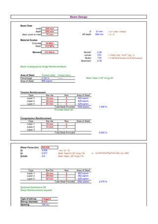
  • 1. Beam Design Beam Data width 200 mm depth 600 mm d' 31 mm .= cc+ sdia + mdia/2 clear cover to main 15 mm eff depth 569 mm .= d - d' reinf. Material Grades Concrete 20 MPa Steel 415 MPa Moment 153 KN-m Mu/bd2 2.36 xumax 273 .= (700/(1100 * (0.87 * fy)) * d Mulim 179 .= 0.36*fck*b*xumax*(d-(0.42*xumax)) Mulim/bd2 2.76 Beam is designed as Singly Reinforced Beam Area of Steel Tension (Ast) Compr (Asc) Percentage 0.782 % ------- Refer Table 2 SP 16 pg 48 Area of Steel 890 sqmm Tension Reinforcement Type Bar dia Nos Area of Steel Layer 1 16 mm 2 402 sqmm Layer 2 20 mm 2 628 sqmm Layer 3 20 mm 2 628 sqmm Total Steel Provided 1659 sqmm 1.458 % Provided Steel OK Compression Reinforcement Type Bar dia Nos Area of Steel Layer 1 16 mm 2 Layer 2 12 mm 2 Layer 3 Total Steel Provided 0.000 % Shear Force (Vu) 300 KN ζv 2.636 .=Vu / (b * d) ζc 0.817 Refer Table 61 SP 16 pg 179 or =(0.85*√(0.8*fck)*√(1+5β)-1)) / (6β) ζcmax 2.8 Refer Table J SP 16 pg 175 Type Bar Dia Nos Area of Steel Layer 1 25 mm 2 982 sqmm Layer 2 25 mm 2 982 sqmm Layer 3 20 mm 2 628 sqmm Total Steel Provided 2592 sqmm 2.278 % Sectional Dimensions OK Shear Reinforcements required Type of stirrup 2 legged Stirrup diameter 8 mm Spacing 100 c/c
  • 2.
  • 3. Steel Calculation Grade Check 7.1 SRB DRB a 0.75 .=(0.87435/100) * (fy/fck)2 a 0.75 .=(0.87435/100) * (fy/fck)2 b -3.611 .=(0.87/100) * (fy) b -3.611 .=(0.87/100) * (fy) c 2.363 .=Mu/bd2 c 2.762 .=Mulim/bd2 -p 0.782 .=-(b±√(b2-4ac))/2a -p 0.955 .=-(b±√(b2-4ac))/2a Ast 890 .=(p*b*d)/100 Astlim 1087 .=(p*b*d)/100 Mu2 -26 .=Mu - Mulim Ast2 -133 .=Mu2/((0.87*fy)*(d-d')) Ast 954 .=Astlim+Ast2 0.0545 d'/d 0.10 0.1 fsc 353 Refer Table F SP 16 pg 13 fcc 8.92 .=0.466*fck Asc -140 .=Mu2/((fsc-fcc)*(d-d')) Min steel % 0.205 .=0.85% / fy Ast 890 Asc -140 Min Steel 233 .=(0.85*b*d) / fy Max Steel 4552 .=0.04*b*d) Ast 890 Asc Shear Calculations Pt provided 2.278 .=(Ast*100)/(b*d) Pc provided .=(Asc*100)/(b*d) β 1.020 .=(0.8*fck)/(6.89*Pt) Shear Capacity of Concrete (Vs) 93 .=ζc*b*d Shear Stg to be caried by Stirrup (Vus) 207 .=Vu-Vs Spacing least of the 4 provide the actual req 100 .=(Asv*0.87fy*d)/Vus min 454 .=(Asv*0.87fy)/(b*0.4) max 427 .=0.75d max 300 .=300mm
  • 4. Slab Design Slab thickness t 125 mm Sunken Depth 325 mm Concrete fck 20 MPa Steel fy 415 MPa Loading Slab Load Sunken Slab Load Dead Load DL 3.125 KN/m Dead Load DL 3.125 KN/m Live Load LL 3.000 KN/m Filler Load FL 5 KN/m Finishes Load WL 1.000 KN/m Live Load LL 3.0 KN/m Total Load Ws 7.125 KN/m Finishes Load WL 1.0 KN/m Factored Load Wsu 11 KN/m Total Load Wsk 11.74 KN/m Factored Load Wsku 18 KN/m Slab Data Slab Type Regular Load 11 KN/m Longer Span (ly) 8.20 m ly/lx ratio 2.05 Shorter Span (lx) 4.00 m Slab type - Loading on edges one way two way Wlonger 21 KN/m .=w*lx/2 .=(w*lx/2) + (1-(1/3)*(lx/ly)2) Wshorter .=w*lx/3 Moments one way two way Mx 21 KN-m .=w*lx2/ 8 .=αx * w*lx2 .=αy * w*lx2 Thickness Check OK .=Mulim > Mux or Muy Deflection 10 mm .= 5*W*l4/(384EI) Astx Refer Chart 4 SP 16 pg 21 or Area of Steel 647 sqmm Refer Table 5-44 SP 16 pg 51-80 Spacing required in mm 8# 10# 12# 16# x y x y x y x x 78 c/c 121 c/c 175 c/c 311 c/c .=ast of bar*1000/ast req Final Ast x y provided
  • 5. Design Calculations ONE WAY TWO WAY a 0.75 .=(0.87435/100) * (fy/fck) 2 a 0.75 .=(0.87435/100) * (fy/fck)2 b -3.611 .=(0.87/100) * (fy) b -3.611 .=(0.87/100) * (fy) cx 1.939 .=Mu/bd2 cy 0.000 .=Mu/bd2 -px 0.616 .=-(b±√(b2-4ac))/2a -py 0.000 .=-(b±√(b2-4ac))/2a Ast 647 .=(p*b*d)/100 Ast 0 .=(p*b*d)/100 Min Ast % mm2 0.12 150 Interpolation 1 0.06 Table 26 IS 456 pg 91 ly/lx αx αy 1.1 0.06 lower upper exact lower upper interptn. value value value value value value 1.2 0.07 0.00 0.00 2.05 #N/A #N/A #N/A 0.06 1.3 0.08 1.4 0.09 1.5 0.09 2 0.11 xumax 50 .= (700/(1100 * (0.87 * fy)) * d Mulim 30 KN-m .= 0.36*fck*b*xumax*(d-(0.42*xumax)) Mulim/bd2 2.76 Mux/bd 2 1.94 Muy/bd2 0.00 E 2.24E+07 I 1.63E-04 .= bd3/12 Defln 9.79 .= 5*W*l4/(384EI)
  • 6. Column Design Design Loads Load Pu 2000 KN Moment Mu 20 KN-m Column Data width b 200 mm depth d 200 mm length l 3.00 meters Grade Concrete fck 20 MPa Steel fy 415 MPa Pu/(fckbd) 2.50 Minimum eccentricity Mu/(fckbd2) 0.01 ex 1.27 mm OK d'/d 0.05 ey 1.27 mm OK Refer Chart 31 of SP 16, Page no: 116 pt/fck 0.18 pt 3.60% Ast 1440 sqmm Number of bars dia nos ast 25 mm 4 1963 sqmm ● ● ● ● ● ● 4- 25# 20 mm 4 1257 sqmm 4- 20# 20 mm 4 1257 sqmm ● ● ● ● ● ● 4- 20# Total 12 4477 sqmm Steel provided OK
  • 7. ACE GROUP ARCHITECTS (P) Ltd. Architects & Consulting Engineers Project : GAT M2 Title : 7.2m lvl Designer : Fahim H. Bepari Date : 18-Sep-2009 Slab thickness t 150 mm Concrete fck 20 MPa Steel fy 415 MPa Loading Slab Load Dead Load DL 3.75 KN/m Live Load LL 2.00 KN/m Garden Load GL 7.20 KN/m Water Proofing Load WL 1.00 KN/m Total Load Ws 13.95 KN/m Factored Load Wsu 21 KN/m Design & Reinforcement Details of Slabs Slab Data Spacing required in mm Slab Name Slab type Slab type Spacing provided in Longer Shorter Loading on edges Moments Thickness Area of Steel Load Span Span ly/lx 8# 10# 12# mm c/c Sl.No Sl. Id Thickness Check Wsu / Wsku ly lx Wlonger Wshorter Mx My Astx Asty x y x y x y x y 1 Sunk 150 mm 21 KN 5.20 m 5.00 m 1.04 + 36 KN/m 35 KN/m 31 KN-m 29 KN-m OK 753 sqmm 706 sqmm 67 c/c 71 c/c 104 c/c 111 c/c 150 c/c 160 c/c + 2 Regular 150 mm 21 KN 5.20 m 2.50 m 2.08 - 26 KN/m 16 KN-m OK 372 sqmm 135 c/c 211 c/c 304 c/c - 3 Regular 150 mm 21 KN 6.50 m 5.80 m 1.12 + 45 KN/m 41 KN/m 46 KN-m 40 KN-m OK 1231 sqmm 1005 sqmm 41 c/c 50 c/c 64 c/c 78 c/c 92 c/c 113 c/c + 3A Regular 150 mm 21 KN 2.00 m 1.10 m 1.82 + 10 KN/m 8 KN/m 3 KN-m 1 KN-m OK 180 sqmm 180 sqmm 279 c/c 279 c/c 436 c/c 436 c/c 628 c/c 628 c/c + 3B Regular 150 mm 21 KN 5.30 m 4.30 m 1.23 + 35 KN/m 30 KN/m 29 KN-m 22 KN-m OK 691 sqmm 504 sqmm 73 c/c 100 c/c 114 c/c 156 c/c 164 c/c 224 c/c + 4 Regular 150 mm 21 KN 35.00 m 2.60 m 13.46 - 27 KN/m 18 KN-m OK 404 sqmm 124 c/c 194 c/c 280 c/c - 5 Regular 150 mm 21 KN 9.20 m 4.10 m 2.24 - 43 KN/m 44 KN-m OK 1154 sqmm 44 c/c 68 c/c 98 c/c - 6 Regular 150 mm 21 KN 9.20 m 4.00 m 2.30 - 42 KN/m 42 KN-m OK 1083 sqmm 46 c/c 73 c/c 104 c/c - 7 Regular 150 mm 21 KN 8.00 m 3.20 m 2.50 - 34 KN/m 27 KN-m OK 638 sqmm 79 c/c 123 c/c 177 c/c -
  • 8. Project NCC Date 18-Sep-09 Grid Floor Analysis & Design Data x direction y direction bf Length of beams Lx = 14.00 meters Ly = 14.00 meters Df Number of beams Nx = 6 nos Ny = 6 nos Spacing of ribs a1 = 2.00 meters b1 = 2.00 meters Depth of beam D = 900 mm D Width of beam bw = 200 mm Width of flange bf = 2000 mm Thickness of flange Df = 150 mm Grade of Concrete fck = 20 MPa bw Grade of Steel fy = 415 MPa a1 Modulas of Elasticity E = 2.2E+07 KN/sqm Loads Live Load 3.00 KN Floor Finish 1.00 KN Other 0.00 KN Loading Calculation Ly Total weight of slab ws = 735.00 KN wbx = 378.00 KN b1 Total weight of beams in x direction Total weight of beams in y direction wby = 345.60 KN Total weight of Live load wll = 588.00 KN Total weight of Floor Finish wff = 196.00 KN Other load wol = Total Load ws+wbx+wby+wll+wff+wol = 2242.60 KN Lx Total Load/sqm q = 11.44 KN/sqm Total Factored Load/sqm Q = 17.16 KN/sqm Design Parameters Ratios Df/D = 0.167 bf/bw = 10.000 Moment of Inertia I = (kx*bw*D3)/12 kx = 2.3 refer Chart 88 of SP 16 pg 215 I = 2.79E-02 Flexural Rigidity of ribs Dx=EI/a1 Dy=EI/b1 Dx = 3.12E+05 Dy = 3.12E+05 Modulus of Shear G=E / (2(1+μ) G = 9.72E+6 KN/sqm Torsional Constants (Polar Sectional Modulus) C1=(1-(0.63*(bw/D))*(bw3*D/3) C2=(1-(0.63*(bw/D))*(D3*bw/3) C1 = 2.06E-3 cum C2 = 4.18E-2 cum Torsional Rigidity Cx=GC1/b1 Cy=GC2/a1 Cx = 1.00E+4 Cy = 2.03E+5 2H=Cx+Cy 2H = 2.13E+5 Dx / Lx4 = 8.13 Dy / Ly4 = 8.13 2H / (Lx2*Ly2) = 5.55 Deflection Check Central Deflection ω=(16*Q/π)/((Dx/Lx4)+(2H/(Lx2*Ly2))+(Dy/Ly4)) ω = 13.09 mm Long Term Deflection Ltdefl. = 3*ω Ltdefl. = 39.28 mm span/deflection (Clause 23.2 IS 456) s/d = 56.00 mm Maximum deflection including long term effects is within permissible limits i.e. Ltdefl < s/d ratio Maximum Moment & Shear Values Max Bending Moments Mx=Dx*(π/Lx)2*ω My=Dy*(π/Ly)2*ω Mx = 206 KN-m My = 206 KN-m Max Torsional Moments Mxy=(Cx*π2*ω1)/(Lx*Ly) Mxy = 7 KN-m Shear Force Qx=[(Dx*(π/Lx)3)+(Cy*(π3/(a*b2)))]*ω Qy=[(Dy*(π/Ly)3)+(Cx*(π3/(b*a2)))]*ω Qx = 48 KN Qy = 48 KN
  • 9. Staircase Design Data Effective Span (l) 5.00 mm Riser (R) 150 mm Thread (T) 300 mm Waist Slab thickness (t) 150 mm Clear Cover 15 mm Effective Depth of Waist Slab (d) 135 mm Grade of Concrete (fck) 20 MPa Grade of Steel (fy) 415 MPa Loading Loads on going Loads on waist slab Self weight of waist slab 4.19 KN/m Self weight of landing slab 3.75 KN/m Self weight of steps 1.88 KN/m Live Load 2.00 KN/m Live Load 3.00 KN/m Floor Finish Load 1.00 KN/m Floor Finish Load 1.00 KN/m Total Load 6.75 KN/m Total Load 10.07 KN/m Factored Load 10.13 KN/m Factored Load 15.10 KN/m Bending Moment Calculate Bending Moment using the equation (W*L*L )/8 ### Bending Moment = 47 KN-m Reaction to be used as UDL = 38 KN ### 60 KN-m Area of Main Steel Ast 1184 sqmm Spacing Diameter of bar 12ø 16ø Spacing across x 96 c/c 170 c/c Provded Main Steel: Area of Distribution Steel Ast 180 sqmm Spacing Diameter of bar 8ø 10ø Spacing across y 279 c/c 436 c/c Provided Distridution Steel:
  • 10. Seismic Zone II Table 2 IS 1893 2002 pg 16 Seismic Intensity z 0.1 Importance factor I 1.5 Table 6 IS 1893 2002 pg 18 Response Reduction Factor R 3 Table 7 IS 1893 2002 pg 23 Lateral Dimension of Building d 65.6 meters Height of the of Building h 50.4 meters with brick infill Fundamental Natural Period Ta 0.560 Type of Soil Medium Soil Spectral Acceleration Coefficient Sa/g 0.000 Design Horizontal Seismic Coefficient Ah 0 Seismic Weight of Building W 680034 KN Design Seismic Base Shear VB 0 KN
  • 11. Date 18-Sep-09 Footing No. F2 1 Footing Size Design Load 1 Pu1 2000 KN Load 2 Pu2 1850 KN Combine load Pcu 3850 KN Design Load Pc 2823 KN Moment in x dir Mux 40 KN-m Moment in y dir Muy 40 KN-m c/c dist b/w col in x dir 2.725 meters c/c dist b/w col in y dir 0.000 meters Col Dim x dir 0.20 meters y dir 0.20 meters SBC q 150 KNm2 Footing Size required A req 18.82 sqmm L 6.00 meters Footing Size Provided B 3.20 meters Area Provided A prvd 19.20 meters x bar 1.309 y bar 0.000 Zx 10.24 Zx 19.20 Nup 151 KNm2 Increase the Footing Size
  • 12. 2 Beam Design Total Load W 151 KNm2 Factored Load Wu 725 KNm2 1.691 meters 2.725 meters 1.584 meters 3.20 meters 6.00 meters 725 KNm2 1.69 meters 2.73 meters 1.58 meters Beam Size width 600 mm depth 900 mm Moment Mb 898 KN-m Design the beam from the BEAM DESIGN SHEET Bottom Reinforcement Type Bar dia Nos Area of Steel Layer 1 25 mm 6 2945 sqmm Layer 2 25 mm 6 2945 sqmm Layer 3 - Total Steel Provided 5890 sqmm Percentage of Steel 1.148 % Top Reinforcement Type Bar dia Nos Area of Steel Layer 1 25 mm 6 2945 sqmm Layer 2 20 mm 6 1885 sqmm Layer 3 - Total Steel Provided 4830 sqmm
  • 13. 3 Slab Design Net upward pressure Nup 151 KNm2 l 1.30 meters /=width of footing from col face Bending Moment Ms 128 KN-m M=Nup*l2/2 Factored Moment Mus 191 KN-m 1.5*Ms Concrete fck 20 MPa Steel fy 415 MPa Minimum Depth Required dmin 264 d=sqrt(Ms/Rumax*1000*b) Depth Provided D 600 mm Clear Cover c 50 mm Effective Cover d' 56 mm Effective Depth d' 544 mm Area of Steel across x dir Spacing c/c in mm 12# 16# 20# 1014 sqmm 112 c/c 198 c/c 310 c/c Ast across x direction 12 mm dia @ 100 mm c/c 1131 sqmm Dist Ast across y direction 8 mm dia @ 175 mm c/c 287 sqmm 4 Shear Check for Slab Vu1 171 KN ζv 0.315 MPa ζc 0.316 MPa Shear Check OK
  • 14. 5 6.00 meters 3.20 meters 600 mm 1.7 meters 2.73 meters 1.6 meters 600 mm 6 - 25 mm dia 6 - 20 mm dia 6 - 25 mm dia 900 mm 6 - 25 mm dia 600 mm 250 mm 8 mm dia @ 175 mm c/c 12 mm dia @ 100 mm c/c 6 - 25 mm dia 6 - 20 mm dia 6 - 25 mm dia 6 - 25 mm dia
  • 15. Design Of Isolated Footing 15 of 37 1 Footing Size Design Load Pu 1500 KN Design Load P 1100 KN Moment in x dir Mux 30 KN-m Moment in y dir Muy 30 KN-m Column size cx 450 mm cy 450 mm SBC q 150 KN/sqm Footing Size required A req 7.33 sqmm L 3.30 meters Footing Size Provided B 2.40 meters Area Provided A prvd 7.92 meters Zx 3.17 Zx 4.36 Net upward pressure Nup 150 KNm2 Footing Size OK 2 Slab Design lx 1.425 ly 0.975 Bending Moment in x dir Mx 228 KN-m Bending Moment in y dir My 107 KN-m Concrete fck 20 MPa Steel fy 415 MPa Minimum Depth Required dmin 288 Depth Provided D 650 mm Clear Cover c 50 mm Effective Cover d' 58 mm Effective Depth d' 592 mm Spacing c/c in mm Area of Steel 12# 16# 20# 1111 sqmm 102 c/c 181 c/c 283 c/c 710 sqmm 159 c/c 283 c/c 442 c/c Minimum Ast required across y direcion Ast across x direction 16 mm dia @ 125 mm c/c 1608 sqmm Ast across y direction 16 mm dia @ 125 mm c/c 1608 sqmm
  • 16. Design Of Isolated Footing 16 of 37 3 One Way Shear along x direction Vu1 449 KN ζv 0.316 MPa ζc 0.317 MPa Vc1 451 KN One Way Shear Check OK 4 One Way Shear along y direction Vu1 284 KN ζv 0.145 MPa ζc 0.260 MPa Vc1 508 KN One Way Shear Check OK 5 Two Way Shear Vu2 1536 KN ζv 0.622 MPa ks*ζc 1.118 MPa Vc1 2759 KN Two Way Shear Check OK
  • 17. Design Of Isolated Footing 17 of 37 L= 3.30 meters 450 450 B= 2.40 meters 250 mm 650 mm 16 mm dia @ 125 mm c/c 16 mm dia @ 125 mm c/c
  • 18. Dimensions of Dome Diameter d= 12600 mm Height h= 3000 mm Thickness t= 150 mm Radius of Sphere r = 8115 mm h = 3.00 m Φ= 50.93 Ѳ= 0 to 50.93 Loading d = 12.60 m Dead Load DL = 3.75 KN/m Live Load LL = 0.10 KN/m 50.93 r = 8.12 m Wind Load WL = 0.10 KN/m 0m Total Load W= 3.95 KN/m 11 5. 0 Factored Load Wu = 5.93 KN/m r =8 Meridional Stress Hoop Stress Ѳ Mt Ѳ Mt 50.93 0.197 MPa 50.93 0.003 MPa 45.00 0.188 MPa 45.00 0.025 MPa 40.00 0.182 MPa 40.00 0.041 MPa 35.00 0.176 MPa 35.00 0.055 MPa 30.00 0.172 MPa 30.00 0.067 MPa 25.00 0.168 MPa 25.00 0.077 MPa 20.00 0.165 MPa 20.00 0.086 MPa 15.00 0.163 MPa 15.00 0.093 MPa 5.00 0.161 MPa 5.00 0.100 MPa 0.00 0.160 MPa 0.00 0.101 MPa Maximum Meridional Stress 0.197 MPa Maximum Hoop Stress 0.101 MPa fck 20 MPa Fy 415 MPa бst 230.00 Area of steel 128 sqmm Area of steel 66 sqmm Bar Dia 10 mm Bar Dia 10 mm Spacing 613 c/c Spacing 1187 c/c Meridional Thrust @ Base 29 KN/m Horizontal Component on Ring Beam 19 KN/m Hoop Tension on Ring Beam 117 KN Area of steel 509 sqmm Bar Dia 16 mm No of Bars 3 nos
  • 19. ACE GROUP ARCHITECTS (P) Ltd. Architects & Consulting Engineers Project : MVJ Block : L-Block Date : 18-Sep-2009 Designer : Fahim H. Bepari Design & Reinforcement Details of Columns Design Constants Design Final Ast Area of Steel Sl Grid Col Col Paramenters Required Col Nos. Load Moment Column Data Grade Ast Req Remark Check Fig No. No type Shape Pu/(fckbdl) Mu/(fckbdl2) d'/d Type 1 Type 2 Total Reinf Provided Ast less than Steel 1 - - C1 R 1500 KN 30 KN-m 30 KN-m 200 mm 750 mm 750 mm 50 mm 3.60 m 20 MPa 415 MPa 0.50 0.01 0.1 0.02 0.40% 600 sqmm min Ast req. 1200 sqmm 4 12 mm 452 sqmm 2 12 mm 226 sqmm 6 679 sqmm provided NOT OK 09/18/2009 Page 19 of 37
  • 20. 19.7 KNm2 Dimensions of Dome Diameter d= 12600 mm Height h= 5000 mm Radius of Sphere r= 6469 mm Φ= 76.87 Ѳ= 0 to 76.87 Loading Dead Load DL = 3.00 KN/m Live Load LL = 0.10 KN/m Other Load OL = 10.00 KN/m Total Load W= 13 KN/m Factored Load Wu = 20 KN/m Vertical Reaction VA = VB = 123.8 KN Horizontal Reaction HA = HB = 234.0 KN Ѳ x y Moment 76.87 0.00 0.00 0 75.00 0.05 0.21 -42 60.00 0.70 1.77 -331 50.00 1.34 2.69 -481 40.00 2.14 3.49 -596 30.00 3.07 4.13 -680 20.00 4.09 4.61 -737 10.00 5.18 4.90 -769 5.00 5.74 4.98 -777 0.00 6.30 5.00 -780 Max Values 780 KN-m
  • 21. h = 5.00 m d = 12.60 m 76.87 r = 6.47 m m 9. 00 646 r= Radial Shear Normal Thrust 0 67 174 67 174 42 59 180 59 180 331 10 224 -10 224 481 56 245 -56 245 596 100 259 -100 259 680 141 265 -141 265 737 178 262 -178 262 769 209 252 -209 252 777 222 244 -222 244 780 234 234 -234 234 234 KN 265 KN
  • 22. ACE GROUP ARCHITECTS (P) Ltd. Architects & Consulting Engineers Project : Jnana Vikas Title : Terrace Floor Designer : Fahim H. Bepari Date : 18-Sep-2009 Beam : CB11 Dimensions of Ring Beam Radius r= 6.30 mts No of supports n= 8 nos Constants Ѳ= 23 deg 0.3927 radians Φm = 9 1/2 0.1658 radians C1 = 0.07 C2 = 0.03 C3 = 0.01 Loading Wu = 10 KN/m FΦ MΦ Mmt Φ Shear Force Bending Torsional Moment Moment deg KN KN-m KN-m 0 24.74 -20.62 0.00 9 1/2 14.29 -0.05 1.57 22 1/2 0.00 10.39 0.00 Beam Data width 300 mm depth 600 mm Equivalent Shear Ve = V+1.6(T/b) = 33 KN T=MΦ Equivalent Moment Mt = T((1+D/b)/1.7) = 1 KN-m Mt = BM due to torsion Me1 = M+Mt = 22 KN-m Me1 = Equivalent BM on tension side Me2 = M-Mt = 20 KN-m Me2 = Equivalent BM on compression side
  • 23. A Load 2700 Moment x-dir y-dir Bottom 0 29 Top 6 137 Col Type Rectangular Column (reinf. on 2 sides) x-dir y-dir Unsupported Length 8250 8250 Col Size 200 900 d'/D 0.05 0.20 d' 40 Concrete 20 Steel 415 D Effective Length Ratio 0.80 from IS Code 0.90 manual Calculation Effective Length to be considered from Manual Calculation Effective Length (le) lex Ley 7425 7425 E Slenderness Ratio le/D 8 Short Column le/b 37 Slender Column Moment due to Slen Muax 0 Muay 372 Min Ecc ex 46.5 ey 23.2 Moment due to ecc Mux 125.55 Muy 62.55 G Reduction of Moments Percentage assumed 2.18 Asc 3924 Puz 2841 k1 K2 Pb x-x 0.22 0.1 367 y-y 0.18 -0.02 291 Kx 0.06 Ky 0.06 Additional Moments due to ecc Max 0 May 21 Modified Initial Moments Mux 3.6 Muy 70.6 Summary of Moments A Moment due to eccentricity + Modified additional moments Mux 126 Muy 83 B Modified initial moments + Modified additional moments Mux 4 Muy 91 C 0.4Muz + Modified additional moments Mux 0 Muy 32 Final Design Loads Pu 2700 Mux 126 Muy 91
  • 24. Project : Delhi Public School Block : Indoor Sports Block Date : 18-Sep-2009 Designer : Fahim H. Bepari Column : C6a Design Loads Pu = 2400 KN Mux = 192 KN-m Muy = 517 KN-m Col Data b = 600 mm D = 750 mm d' = 40.0 mm d'/D = 0.10 d'/b = 0.10 Material Grades fck = 20 MPa fy = 415 MPa Design Constants Steel % pt = 1.2 Ast = 5400 sqmm pt/fck = 0.06 Min Ast = 3600 sqmm Pu/fck*b*D = 0.27 Mux/fck*b*D2 = 0.11 Muy/fck*b*D2 = 0.11 Puz = 5682 Mux1 = 743 Muy1 = 594 Pu/Puz = 0.42 Mux/Mux1 = 0.26 Muy/Muy1 = 0.87 αn = 1.37 (Mux/Mux1)αn + (Muy/Muy1)αn 0.98 Steel Percentage OK Steel Details nos dia ast Type 1 4 20 mm 1257 sqmm Type 2 8 16 mm 1608 sqmm Total Steel 12 - 2865 sqmm Percentage 0.64%
  • 25. Simply supported beam Simply supported beam with UDL with Point Load Load W 30 KN/m 10 KN/m Length l 5.60 m 5.00 m Elasticity of Concrete Ec 22000000 MPa 22000000 MPa = 5000(√fck) Width b 0.20 m 0.20 m Depth d 0.45 m 0.60 m Moment M 126.42 m 40.63 m Reaction R 90.30 m 32.50 m Moment of Inertia = Ixx 0.0015 mm4 0.0036 mm4 bd3/12 Deflection 11.5 mm 0.3 mm dy Formula 5Wl4/384EI Wl3/48EI
  • 26. Cantilever beam Cantilever beam with UDL with Point Load 1400 KN/m 10 KN/m 3.80 m 5.00 m 22000000 MPa 22000000 MPa 1.50 m 0.20 m 1.10 m 0.60 m 2601.46 m 40.63 m 2738.38 m 32.50 m 0.1664 mm4 0.0036 mm4 10.0 mm 5.3 mm Wl4/8EI Wl3/3EI
  • 27. 125 mm 150 mm 175 mm 200 mm Span Moment Ast Moment Ast Moment Ast Moment Ast Mu/bd2 Spacing Mu/bd2 Spacing Mu/bd2 Spacing Mu/bd2 Spacing (KNm) (mm2) (KNm) (mm2) (KNm) (mm2) (KNm) (mm2) 12# @ 243 c/c 12# @ 293 c/c 12# @ 336 c/c 12# @ 306 c/c 3 16 1.45 465 17 1.01 386 18 0.75 337 19 0.59 369 16# @ 432 c/c 16# @ 521 c/c 16# @ 597 c/c 16# @ 546 c/c 12# @ 169 c/c 12# @ 211 c/c 12# @ 253 c/c 12# @ 269 c/c 3.5 22 2 669 23 1.36 536 25 1.04 447 26 0.8 421 16# @ 301 c/c 16# @ 375 c/c 16# @ 450 c/c 16# @ 479 c/c 12# @ 126 c/c 12# @ 156 c/c 12# @ 181 c/c 12# @ 202 c/c 4 28 2.54 899 30 1.78 723 32 1.33 624 34 1.05 559 16# @ 224 c/c 16# @ 278 c/c 16# @ 322 c/c 16# @ 360 c/c 12# @ 118 c/c 12# @ 137 c/c 12# @ 153 c/c 4.5 38 2.25 956 41 1.71 824 44 1.36 741 16# @ 210 c/c 16# @ 244 c/c 16# @ 271 c/c 12# @ 109 c/c 12# @ 121 c/c 5 50 2.08 1039 54 1.67 931 16# @ 194 c/c 16# @ 216 c/c 12# @ 85 c/c 12# @ 98 c/c 5.5 61 2.54 1327 65 2.01 1155 16# @ 152 c/c 16# @ 174 c/c 12# @ 80 c/c 6 77 2.38 1418 16# @ 142 c/c
  • 28. Span 150 mm 175 mm 200 mm 12# @ 293 c/c 12# @ 336 c/c 12# @ 306 c/c 3 16# @ 521 c/c 16# @ 597 c/c 16# @ 546 c/c 12# @ 211 c/c 12# @ 253 c/c 12# @ 269 c/c 3.5 16# @ 375 c/c 16# @ 450 c/c 16# @ 479 c/c 12# @ 156 c/c 12# @ 181 c/c 12# @ 202 c/c 4 16# @ 278 c/c 16# @ 322 c/c 16# @ 360 c/c 12# @ 118 c/c 12# @ 137 c/c 12# @ 153 c/c 4.5 16# @ 210 c/c 16# @ 244 c/c 16# @ 271 c/c 12# @ 109 c/c 12# @ 121 c/c 5 16# @ 194 c/c 16# @ 216 c/c 12# @ 85 c/c 12# @ 98 c/c 5.5 16# @ 152 c/c 16# @ 174 c/c 12# @ 80 c/c 6 16# @ 142 c/c
  • 29. DESIGN OF RETAINING WALL 1 Preliminary Data i) Height of RW h 3.00 meters ii) Soil Density γs 18 KN/cum iii) SBC qo 250 KN/sqm 30 degrees iv) Angle of repose Ø 0.524 radians 0 degrees v) Surcharge Angle Ө 0.000 radians vi) Coefficient of friction µ 0.5 vii) Surcharge Load Ws 4 KN/sqm 2 Pressure Coefficients Active Pressure Coefficients i) =(cosӨ-√(cos2Ө-cos2Ø)*cosӨ) / (cosӨ+√(cos2Ө- Ca 0.333 cos2Ø)) Passive Pressure Coefficients ii) Cp 3.00 = (1+SinØ) / (1+SinØ) 3 Preliminary Dimensions Proposed Adopted i) Thickness of Stem ts - 0.20 meters ii) Thickness of footing base slab tb = 0.08 * (h + hs) 0.24 meters 0.30 meters Length of base slab L = 1.5 * √(Ca/3) * (h + hs) 1.61 meters iii) 2.00 meters or L = 0.6h to 0.65h 2.09 meters iv) Extra Height of Retaining Wall due to Surcharge hs = Ws/γs 0.22 meters v) Total Height of Retaining Wall due to Surcharge Hs = h+hs 3.22 meters vi) Extra Height of RW due to inclined back fill hi = (L-ts)* tanӨ 0.00 meters vii) Total Height of RW due to inclined back fill Hi = h+hi 3.00 meters viii) Design Height of RW considered H = Max of H1 & H2 3.22 meters 4 Stability against Overturning i) Active pressure due Surcharge Load Pa1 = Ca*Ws*h 4 KN ii) Active pressure due Backfill Load Pa2 = Ca*γs*h2 / 2 27 KN iii) Total Load on stem Pa = Pa1 + Pa2 31 KN iv) Overturning Moment Mo= (Pa1 * h/2) +(( Pa2*CosӨ)* h/3) 33 KNm v) Load Lever arm from end of stem Moment W1 Backfill Load = (L-ts)*(h-tb)*γs 87 KN (L-ts) / 2 0.90 meters 79 KNm W2 Surcharge Load = Ca*Ws*h 4 KN (L-ts) / 2 0.90 meters 4 KNm W3 Inclined Backfill Load = ((L-ts)*hi)/2*γs 0 KN (L-ts) / 3 0.60 meters 0 KNm W4 Stem self weight = ts*(h-tb)*γconc 14 KN (L- (ts/2))/2 0.95 meters 13 KNm W5 Base self weight = L*tb*γconc 15 KN L/2 1.00 meters 15 KNm W6 Downward component = Pa*sinӨ 0 KN 0 KNm W6 Other Load 0 KNm ∑W 120 KN ∑Mw 110 KNm vi) Distance of Resultant Vertical Force from end of heel xw=∑Mw/∑W 0.92 meters vii) Stabilizing Moment Mr =∑W * (L - xw) 130 KNm viii) Factor of Safety against OVERTURNING (FS)OT = 0.9 * (Mr/Mo) 3.54 > 1.4 Safe against Overturning 5 Stability against Sliding i) Sliding Force Pa*CosӨ 31 KN ii) Resisting Force F = µ*∑W 60 KN iii) Factor of Safety against SLIDING (FS)SL=0.9*(F/(Pa*CosӨ)) 1.74 > 1.4 Safe against Sliding Shear Key not required iv) Shear key Design x 0.00 meters a) Shear Key Size y 0.00 meters b) Distance from stem z 0.00 meters c) Heigth of exacavation h1 0.00 meters d) Heigth of exacavation h2 = h1 + y + (z * tanØ) 0.00 meters e) Passive Pressure Pp = Cp*γs*(h12-h22) / 2 0 KN v) Revised Factor of Safety against SLIDING (FS)sliding = 0.9 * ((F+Pp)/(Pa*CosӨ)) 1.74 > 1.4 Safe against Sliding 6 Soil Pressures at footing base i) Resultant Vertical Reaction ∑W = R 120 KN ii) Distance of R from heel Lr = (Mw+Mo)/R 1.19 meters iii) Eccentricity e = Lr- L/2 0.19 meters Eccentricity lies within middle third of the base hence OK iv) Pressure Distridution on soil qmax = R/L * (1+(6*e/L)) 95 KN/sqm qmin = R/L * (1-(6*e/L)) 25 KN/sqm Max Pressure qmax<SBC hence pressure on base is OK Pressure at junction of stem and q =q -((q -q )/L)*t ) v) 88 KN/sqm heel sh max max min s
  • 30. DESIGN OF L Shaped Cantilever RETAINING WALL 1 Preliminary Data i) Height of Retaining Wall h 3.00 meters ii) Soil Density γs 18 KN/cum iii) SBC qo 250 KN/sqm iv) Angle of repose Ø 30 degrees 0.524 radians v) Surcharge Angle Ө 0 degrees 0.000 radians vi) Coefficient of friction µ 0.5 vii) Surcharge Load Ws 4 KN/sqm 2 Pressure Coefficients i) Active Pressure Coefficients Ca 0.333 =(cosӨ-√(cos2Ө-cos2Ø)*cosӨ) / (cosӨ+√(cos2Ө-cos2Ø)) ii) Passive Pressure Coefficients Cp 3.00 = (1+SinØ) / (1+SinØ) 3 Preliminary Dimensions Proposed Adopted i) Thickness of Stem ts min 200mm 0.20 meters ii) Thickness of footing base slab tb = 0.08 * (h + hs) 0.24 meters 0.30 meters iii) Length of base slab L = 1.5 * √(Ca/3) * (h + hs) 1.61 meters 2.20 meters L = 0.6h to 0.65h 2.09 meters iv) Extra Height of Retaining Wall due to Surcharge hs = Ws/γs 0.22 meters v) Total Height of Retaining Wall due to Surcharge Hs = h+hs 3.22 meters vi) Extra Height of RW due to inclined back fill hi = (L-ts)* tanӨ 0.00 meters vii) Total Height of RW due to inclined back fill Hi = h+hi 3.00 meters viii) Design Height of RW considered H = Max of H1 & H2 3.22 meters 4 Stability against Overturning i) Active pressure due Surcharge Load PHS = Ca*Ws*h 4 KN ii) Active pressure due Backfill Load PH = Ca*γs*h2 / 2 31 KN iii) Total Load on stem (Force) Pa = PHS + PH 35 KN iv) Overturning Moment due to Imposed load MOIL = PHS*h/2 7 KN v) Overturning Moment due to Backfill load MODL = PH*h/3 33 KN vi) Overturning Moment Mo = (1.2*MDIL) + (1.4*MOIL) 50 KN v) Load Lever arm at end of stem Moment W1 Backfill Load = (L-ts)*(h-tb)*γs 105 KN ((L-ts) / 2) + ts 1.20 meters 126 KNm W2 Inclined Backfill Load = ((L-ts)*hi)/2*γs 0 KN ((L-ts) / 3) + ts 0.87 meters 0 KNm W3 Stem self weight = ts*(h-tb)*γconc 15 KN ts / 2 0.10 meters 1 KNm W4 Base self weight = L*tb*γconc 17 KN L/2 1.10 meters 18 KNm ∑W 136 KN ∑Mw 146 KNm viii) Mw not less than (1.2*MODL) +(1.4*MOIL) Safe against Overturning -clause 20.1 page 33 of IS 456 2000 5 Stability against Sliding i) Sliding Force Pa = PHS + PH 35 KN ii) Resisting Force F = µ*∑W 68 KN iii) (FS)SL= (0.9*F)/(Pa) 1.73 > 1.4 Safe against Sliding -clause 20.2 page 33 of IS 456 2000 6 Soil Pressures at footing base i) Net Moment at toe Mn = Mw - Mo 105 KN ii) Point of application of Resultant R x = Mn/W 0.77 meters iii) Eccentricity e = (L/2) - x 0.33 meters L/6= 0.37 e<L6 Eccentricity lies within middle third of the base hence OK iv) Pressure Distridution on soil qmax = W/L * (1+(6*e/L)) 117 KN/sqm qmin = W/L * (1-(6*e/L)) 7 KN/sqm Max Pressure qmax<SBC hence pressure on base is OK Pressure at junction of stem and qsh=qmax-((qmax-qmin)/L)*ts) v) 107 KN/sqm heel
  • 31. 7 Constants for Working Stress Method Design Constants i) Grade of concrete 20 MPa ii) Grade of steel 415 MPa iii) Compr stress in concrete c 7.0 table 21 page 81 IS 456 iv) Tensile stress in steel t 230 v) Modular ratio m = 280/3c 13.33 vi) Neutral axis depth factor k=mc/(mc+t) 0.289 vii) Lever arm j = 1 - k/3 0.904 viii) Factor R= cjk / 2 0.913 8 Design A) Stem i) Beanding Moment at base of stem M = MODL + MOIL 40 KN/m ii) Thickness required dreq=√(Ms/(R*b) 0.01 meters iii) Thickness provided ts 0.20 meters Thickness of Stem is OK iv) Ast required Ast = M/(t*j*tse) 1387 sqmm v) Ast provided 16 mm dia @ 125 mm c/c 1608 sqmm vi) Percentage of Steel pt = Ast/(b*d) 0.99 % Steel OK B) Base Slab Force Lever arm from end of stem Moment i) Force due to backfill+surcharge = (H2-tb)*(L-ts)*γs 105 (L-ts) / 2 1.00 meters 105 KNm ii) Force due to inclined backfill = hi/2*(L-ts)*γs 0 (L-ts) / 3 0.67 meters 0 KNm iii) Self Weight of base slab =L *tb*γconc 17 L/2 1.10 meters 18 KNm ∑Ws 122 Md 123 KNm vi) Upward soil pressure Nup = ((qsh+qmin)/2)*(L-ts) 114 ((qsh+(2*qmin))/(qsh+qmin)) / 1.59 meters 181 KNm Downward Pressure is greater ((L-ts)/3) Mu 181 KNm v) Bending Moment Msh = Mu-Md 58 vi) Thickness required dreq=√(Ms/(R*b) 0.25 meters Thickness of Stem is OK vii) Thickness provided ts 0.30 meters viii) Ast required Ast = M/(t*j*tse) 1157 sqmm ix) Ast provided 16 mm dia @ 150 mm c/c 1340 sqmm x) Percentage of Steel pt = Ast/(b*d) 0.48 % Steel OK C) Reinforcement Details FILL
  • 32. DESIGN OF Reverse L Shaped Cantilever RETAINING WALL 1 Preliminary Data i) Height of Retaining Wall h 3.00 meters ii) Height of Plinth Fill hp 0.50 meters iii) Soil Density γs 18 KN/cum iv) SBC qo 250 KN/sqm Angle of repose Ø 30 degrees v) 0.524 radians Surcharge Angle Ө 0 degrees vi) 0.000 radians vii) Coefficient of friction µ 0.5 vii) Surcharge Load Ws 4 KN/sqm 2 Pressure Coefficients i) Active Pressure Coefficients Ca 0.333 =(cosӨ-√(cos2Ө-cos2Ø)*cosӨ) / (cosӨ+√(cos2Ө-cos2Ø)) ii) Passive Pressure Coefficients Cp 3.000 = (1+SinØ) / (1+SinØ) 3 Preliminary Dimensions Proposed Adopted i) Thickness of Stem ts min 200mm 0.20 meters ii) Thickness of footing base slab tb = 0.08 * (h + hs) 0.24 meters 0.45 meters iii) Length of base slab α = 1 - (q0/2.7*γs*H) -0.60 meters if sloped backfill L = H*sqrt((Ca*cosβ)/((1-α)*(1+3α)) 0.00 meters α = 1 - (q0/2.2*γs*H) -0.96 meters 2.45 meters if horizontal backfill L = 0.95*H*sqrt((Ca)/((1-α)*(1+3α)) 0.00 meters L = 0.6h to 0.65h 2.09 meters iv) Extra Height of Retaining Wall due to Surcharge hs = Ws/γs 0.22 meters v) Total Height of Retaining Wall due to Surcharge Hs = h+hs 3.22 meters vi) Extra Height of RW due to inclined back fill hi = (L-ts)* tanӨ 0.00 meters vii) Total Height of RW due to inclined back fill Hi = h+hi 3.00 meters viii) Design Height of RW considered H = Max of H1 & H2 3.22 meters 4 Stability against Overturning i) Active pressure due Surcharge Load PHS = Ca*Ws*h 4 KN ii) Active pressure due Backfill Load PH = Ca*γs*h2 / 2 31 KN iii) Total Load on stem (Force) Pa = PHS + PH 35 KN iv) Overturning Moment due to Imposed load MOIL = PHS*h/2 7 KN v) Overturning Moment due to Backfill load MODL = PH*h/3 33 KN vi) Overturning Moment Mo = (1.2*MDIL) + (1.4*MOIL) 50 KN v) Load Lever arm at start of heel Moment W1 Front fill Load = (L-ts)*(hp-tb)*γs 2 KN ((L-ts) / 2) 1.13 meters 2 KNm W3 Stem self weight = ts*(h-tb)*γconc 14 KN (ts/2) + (L-ts) 2.35 meters 33 KNm W4 Base self weight = L*tb*γconc 28 KN L/2 1.23 meters 34 KNm W5 Other Load PT Beam Load 0 KN ∑W 43 KN ∑Mw 69 KNm viii) Mw not less than (1.2*MODL) +(1.4*MOIL) Safe against Overturning -clause 20.1 page 33 of IS 456 2000 5 Stability against Sliding i) Sliding Force Pa = PHS + PH 35 KN ii) Resisting Force F = µ*∑W 22 KN iii) (FS)SL= (0.9*F)/(Pa) 0.55 < 1.4 Unsafe against Sliding -clause 20.2 page 33 of IS 456 2000 5a Shear key Design x 0.30 meters a) Shear Key Size y 0.30 meters b) Distance from stem z 0.30 meters c) Heigth of exacavation h1 0.60 meters d) Heigth of earth mobilization h2 = h1 + y + (z * tanØ) 1.07 meters e) Passive Pressure Pp = Cp*γs*(h12-h22) / 2 21 KN v) Revised Factor of Safety against SLIDING (FS)sliding = 0.9 * ((F+Pp)/(Pa*CosӨ)) 1.09 > 1.4 Unsafe against Sliding. Shear Key Required 6 Soil Pressures at footing base
  • 33. i) Net Moment at toe Mn = Mw - (MOIL+MODL) 28 KN ii) Point of application of Resultant R x = Mn/W 0.65 meters iii) Eccentricity e = (L/2) - x 0.58 meters L/6= 0.41 e>L6 Eccentricity lies outside the middle third of the base. Revise the base dimensions iv) Pressure Distridution on soil qmax = W/L * (1+(6*e/L)) 43 KN/sqm qmin = W/L * (1-(6*e/L)) -7 KN/sqm Max Pressure qmax<SBC hence pressure on base is OK Pressure at junction of stem and qsh=qmax-((qmax-qmin)/L)*ts) v) 39 KN/sqm heel
  • 34. 7 Constants for Working Stress Method Design Constants i) Grade of concrete 20 MPa ii) Grade of steel 415 MPa iii) Compr stress in concrete c 7.0 table 21 page 81 IS 456 iv) Tensile stress in steel t 230 v) Modular ratio m = 280/3c 13.33 vi) Neutral axis depth factor k=mc/(mc+t) 0.289 vii) Lever arm j = 1 - k/3 0.904 viii) Factor R= cjk / 2 0.913 8 Design A) Stem i) Beanding Moment at base of stem M = MODL + MOIL 40 KN/m ii) Thickness required dreq=√(Ms/(R*b) 0.01 meters iii) Thickness provided ts 0.20 meters Thickness of Stem is OK iv) Ast required Ast = M/(t*j*tse) 1387 sqmm v) Ast provided 16 mm dia @ 120 mm c/c 1676 sqmm vi) Percentage of Steel pt = Ast/(b*d) 0.99 % Steel OK B) Base Slab Force Lever arm from end of stem Moment i) Force due to Frontfill = (L-ts)*(hp-tb)*γs 2 (L-ts) / 2 1.13 meters 2 KNm iii) Self Weight of base slab = L* tb * γconc 28 L/2 1.23 meters 34 KNm ∑Ws 30 Md 36 KNm vi) Upward soil pressure Nup = ((qsh+qmin)/2)*(L-ts) 35 ((qsh+(2*qmin))/(qsh+qmin)) / 1.03 meters 36 KNm Upward Pressure is greater ((L-ts)/3) Mu 36 KNm v) Bending Moment Msh = Mu-Md 0 vi) Thickness required dreq=√(Ms/(R*b) 0.01 meters Thickness of Stem is OK vii) Thickness provided ts 0.45 meters viii) Ast required Ast = M/(t*j*tse) 2 sqmm ix) Ast provided 12 mm dia @ 150 mm c/c 754 sqmm x) Percentage of Steel pt = Ast/(b*d) 0.00 % Steel OK C) Reinforcement Details FILL