This document summarizes structural design considerations for deflection and cracking in reinforced concrete beams. It discusses:
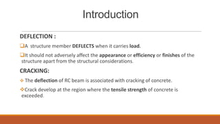
1) How deflection occurs when a structure carries a load and guidelines for limiting deflection to prevent issues.
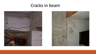
2) How cracking develops in concrete when tensile strength is exceeded from beam deflection.
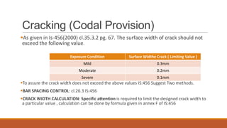
3) Codal provisions for maximum allowable crack widths depending on exposure conditions.
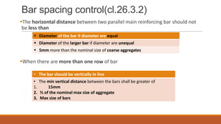
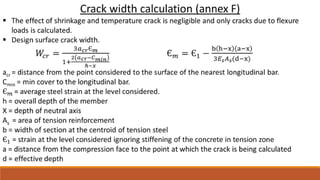
4) Methods for controlling crack widths, including bar spacing and calculating crack widths.
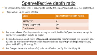
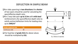
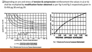
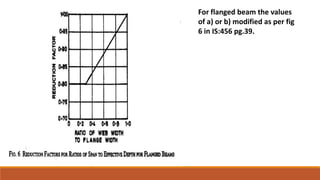
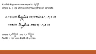
5) Codal provisions for limiting span-to-depth ratios to control deflections.
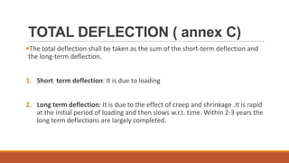
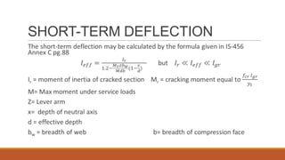
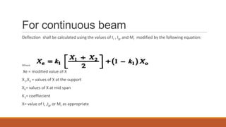
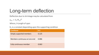
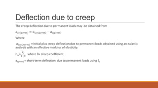
6) How to calculate short-term and long-term deflections, including effects of creep and shrinkage.