Rapid tooling far better than conventional tooling Nicerapid Tooling
There are a number of added benefits associated with the rapid tooling that include, but not limited to.For More Information Visit....http://www.nice-rapidtooling.com/
Rapid tooling far better than conventional tooling Nicerapid Tooling
There are a number of added benefits associated with the rapid tooling that include, but not limited to.For More Information Visit....http://www.nice-rapidtooling.com/
This presentation deals with the rapid prototyping fundamentals, rapid tooling vs conventional tooling and types of RP such as stereolithography,fused deposition modelling , laminated object manufacturing , 3d printing and selective laser sintering.
Skorpion Engineering arranging of all the technologies of Rapid Prototyping and Rapid Manufacturing is able to construct any object starting from a mathematical 3D CAD model. Today, all sectors, from medical to automotive, from design to fashion recognize the prototype as a key point for evaluating cost, schedule, market response to any object.
Selective Laser Sintering is one of the most used processes of Rapid Prototyping. It is a powder based process where powder of different metals/materials get sintered by LASER.
BAHIR DAR UNIVERSITY BAHIR DAR INSTITUTE OF TECHNOLOGY (BiT) FACULTY OF MECHANICAL AND INDUSTRIAL ENGINEERING Rapid Prototyping & Reverse Engineering [MEng6123]
Rapid Prototyping Techniques
Rapid Prototyping Techniques
They can be categorized by material: photopolymer, thermoplastic, and adhesives.
Photopolymer systems start with a liquid resin, which is then solidified by exposure to a specific wavelength of light.
Thermoplastic systems begin with a solid material, which is then melted and fuses upon cooling.
The adhesive systems use a binder to connect the primary construction material
Rapid Prototyping Techniques
The initial state of material can come in either
solid, liquid or powder state
The current range materials include
paper, polymer, nylon, wax, resins, metals and ceramics.
Liquid Based RP Systems
Solidification of a Liquid Polymer
These process involve the solidification of a resin via electromagnetic radiation
There are different processes in this category
Stereolithography (SL)
Liquid Thermal Polymerization (LTP)
Beam Interference Solidification (BIS)
Solid Ground Curing (SGC)
Objet Quadra Process (Objet)
Holographic Interference Solidification
Liquid Based RP Systems
Stereolithography (SL)
Principle of Operation
Patented in 1986,
Started the RP revolution
Developed by 3D Systems, Inc.
Most popular RP methods.
The technique builds 3D models from liquid photosensitive polymers that solidify when exposed to ultraviolet light.
Builds plastic parts a layer at a time by tracing a laser beam on the surface of a vat of liquid photopolymer.
The liquid photopolymer, quickly solidifies wherever the laser beam strikes the surface of the liquid
Direct metal laser sintering (DMLS) Is an additive manufacturing technique that uses a laser as the power source to sinter powdered material (typically metal), aiming the laser automatically at points in space defined by a 3D model, binding the material together to create a solid structure.
.ss. Metal powder (20μm diameter) without binder is completely melted by scanning of a high power laser beam. The density of a produced part is about 98 %. SLS has about 70 %. One advantage of DMLS compared to SLS is the small size of particles which enables very detailed parts.
Working principle:
Direct metal laser sintering (DMLS) is an AM process by which digital 3Ddesign data is used to build up a component in layers by depositing metal material.
The system starts by applying a thin layer of the powder material to the building platform
After each layer, a laser beam then fuses the powder at exactly the points defined by the computer-generated data, using a laser scanning optic . The platform is then lowered and another layer of powder is applied . Once again the material is fused so as to bond with the layer below at the predefined points resulting in a complex part. Thereby not only the part but also the final material is created in the process and defines the unique characteristics of this technology. Every single welding line creates a new micro segment of the final part and can therefore be monitored. Stacking all monitoring information on top of each other, we can visualize a 3D model of the part quality.
ExOne Direct Material Printing - Binder Jetting TechnologyRicardo Toledo
Unique binder-based 3D printing technology was developed at MIT.
ExOne uses Binder Jetting technology to 3D print complex parts in industrial-grade materials. Binder Jetting is an additive manufacturing process in which a liquid binding agent is selectively deposited to join powder particles. Layers of material are then bonded to form an object. The printhead strategically drops binder into the powder. The job box lowers and another layer of powder is then spread and binder is added. Over time, the part develops through the layering of powder and binder.
Binder Jetting is capable of printing a variety of materials including metals, sands and ceramics. Some materials, like sand, require no additional processing. Other materials are typically cured and sintered and sometimes infiltrated with another material, depending on the application. Hot isostatic pressing may be employed to achieve high densities in solid metals.
3D Printers:Electronics, Materials and High Quality Printsmhk3000
This presentation discusses the best practices when doing a 3D Print. Furthermore, it educates the user when he/she is buying a 3D Printer. It discusses Materials, Electronics and how to achieve High Quality Prints
The presentation contains all the data about 3D printing. How it is done, what are the various ways of 3D printing process along with its Advantage & Disadvantage, type of raw material used, etc....
Quick overview on the main applications of fused filament fabrication (aka FDM) 3d printing split by market (professional, education and makers) and use case (rapid prototyping, rapid tooling, rapid manufacturing, lessons, hobby...).
For more information please contact me via Linkedin: https://www.linkedin.com/in/gerardgarciatorrents
very good to have a this type of context in theRemember that a 3D printer works by depositing raw material layer by layer along the X, Y and Z axis. The accuracy of the 3D printer therefore depends upon the minimum distance the nozzle can travel vertically (the Z axis). Minimum the distance it can move, more the points along the sinusoid that it can capture, and better the accuracy.For Stratasys 3D printers, which are the pioneers of the FDM printers, the current best possible dimensional accuracy is about 0.127 mm. Of course, the choice of raw material too plays an important part in achieving dimensional stability. It should also be remembered that the accuracy comes at the cost of printing time required.
A few advantages of FDM 3D printers include: slideshare FDM 3D Printers find application in:
creating prototypes for Fit, Form and Function testing
rapid tooling patterns and mould inserts
creating and testing any parts that work under thermal loads
production of precise and complex end-use parts e.g. jigs & fixtures
Sectors that use FDM 3D Printers include:
Automotive
Aerospace
Manufacturing
Industrial
Medical
Architecture
Consumer Goods
Fashion
Education & Research
Overall, FDM 3D printers give a very high value for money and a
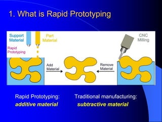
1. 1. What is Rapid Prototyping
Rapid Prototyping: Traditional manufacturing:
additive material subtractive material
2. 1.1 Characteristics of RP
A technology that produces models and
prototype parts from 3D CAD model data, CT
and MRI scan data, and model data created from
3D object digitizing systems
RP systems join together liquid, powder and
sheet materials to form parts
Layer by layer, RP machines fabricate plastic,
wood, ceramic and metal objects
RP also known as Solid Freeform Fabrication (SFF)
or Layer Manufacturing (LM)
3. Build
Prototype
1.2 Basic process of RP
Three stages: pre-processing, building, and
post processing
RP Process Post Process
Pre Process
Generate
.STL file
Build Supports
if needed
Slicing
Remove
Supports
Clean Surface
Post Cure if needed
Part Completed
CAD Model
Surface/Solid
Model
in RP
systems
in CAD
4. 1.3 Benefits of RP
Shorten time to market &
reduced development cost
THE COST OF CHANGE
PHASE COST
Conceptual modeling $10
Detail design $100
Prototype/test $1,000
Manufacturing $10,000
Product release $100,000
Source: Wohlers Associates
3D visualization of product
designs
Esure that customers have
a clear understanding
“A picture is worth a
thousand words; a model is
worth a thousand pictures.”
Improved product quality
RP enable more design
iterations in a given time
5. 2. Common types of RP
The first RP system was introduced in 1988
Common types of RP technologies now:
- StereoLithography (SL)
- Fused Deposition Modeling (FDM)
- Selective Laser Sintering (SLS)
- Laminated Object Manufacturing (LOM)
- 3D Printing (3DP)
6. 2.1 Stereo-Lithography (SL)
1. The elevator lowered by 1
layer deep;
2. The Blade sweep across
the vat, apply an even layer
of resin on top of the part;
3. As the laser beam strikes
the resin surface, the liquid
resin is hardened to a solid
plastic;
4. Loop through the three
steps to cure a new layer.
Laser
Scanning
Mirror
Liquid Resin
Cured resin
to form model
Re-coating
Blade
7. Stereo-Lithography Apparatus (SLA)
Representative:
from 3D Systems, Inc.
Materials:
photocurable resins
Adv. & Disadvantages:
Good dimensional
accuracy
Good surface finish
Narrow range of
materials
Relatively high cost
Post curing
Application areas:
- Prototypes for concept
models;
- Form-fit for assembly
tests and process
planning;
- Models for investment
casting, replacement of
the wax pattern;
- Patterns for metal
spraying, epoxy molding
and other soft tooling
8. 2.2 Fused Deposition Modeling (FDM)
1. Extrusion head and
elevator move to start
position;
2. The head extrude
layer of support;
3. The head extrude
layer of model;
4. Loop through the three
steps to build the next
layer.
Part
Heated extrusion
head
Model & Support Filaments
Elevator & Platform
9. Fused Deposition Modeling (FDM)
Representative:
from Stratasys Inc.
Materials:
thermoplastic material such
as wax, ABS plastic &
elastomer
Adv. & Disadvantages:
clean, simple, easy to operate
A good variety of material
Mid range performance/cost
Relative low accuracy
Poor strength in vertical
direction
- Slow for building a mass part
Application areas:
- Conceptual modeling;
- Fit, form and functional
test;
- Pattern for investment
casting;
- The MABS (methy
methacrylate ABS)
material is particularly
suitable for medical
applications.
10. 2.3 Selective Laser Sintering (SLS)
1. Piston of the part built
chamber lower by one layer;
2. Piston of powder cartridges
raise up;
3. Roller spread powder
evenly over the built
surface;
4. Laser beam scan over the
top of the part, melting the
powder and fuse it to the
previous layer;
5. Loop through the four steps
to build the next layer.
Laser
Scanning
Mirror
Roller
Piston
Powder
cartridges
Build
Chamber
11. Selective Laser Sintering (SLS)
Representative:
from DTM Corporation
Materials:
powder material such as nylon,
wax, polycarbonate, metal,
ceramic, elastomer, etc.
Adv. & Disadvantages:
Large variety of material available
Produced in short time
No additional support required
No post curing required
Heat up powder & cool down part
Smoothness of surface restricted
Expensive running cost
Toxic gases generated
Application areas:
- Visual representation;
- durable enough for most
functional tests;
- Pattern for making soft
tooling, casting;
- Direct manufacture of metal
mould;
- Small batch production run.
12. 2.4 Laminated Object Manufacturing
(LOM)
1. The sheet material is stretched
from the supply roller to the
take-up roller;
2. The heated laminated roller
passes over the sheet bonding
it to the previous layer;
3. Laser cuts the profile of that
layer and hatching the excess
material for later removal;
4. Loop through the three steps
to form a new layer.
13. Laminated Object Manufacturing (LOM)
Representative:
from Helisys
Materials:
sheet material such as paper,
plastic, ceramic, composite etc.
Adv. & Disadvantages:
A relatively high speed process
No post curing required
No support structure required
Simple to use
The most commonly used
material is only paper
Must be post processed
immediately
Restricted to build complex
parts
Fire hazard occasionally
happened
Application areas:
- Visual representation;
- Concept modeling;
- Pattern for sand casting;
14. 2.5 3D Printing (3DP)
less costly and less capable
variation of RP technology
Companies install them in offices
near their CAD systems for concept
modeling.
15. 3. Application cases of RP
Common applications
of the RP technology:
Design
concept models
Marketing
models for tenders,
customer feedback,
presentations and
brochures
Test & Analysis
functional testing;
strong models for wind
tunnel and stress
analysis
Tooling
masters and patterns
for a broad range of
manufacturing
processes
Medicine
artificial limbs, tools and
instruments
16. 4. Rapid Tooling Making (RTM)
INDIRECT RPM: Pattern created by RP used to fabricate
tool
- RP-fabricated part as master in making silicon-rubber
mold (subsequently used as production mold)
- RP patterns to make sand molds for sand casting
- Fabrication of patterns of low-melting pt. materials for
Investment casting
DIRECT RPM: RP used to make the tool itself
- 3D printing to create die geometry in metallic powders
(followed by sintering & infiltration)
17. 4. Rapid Tooling Making (RTM)
low volume (from
tens to hundreds)
- Soft Tooling
Intermediate (from
hundreds to
thousands)
- Metal filled Epoxy
Tooling
- Powdered Metal
Tooling
Aluminum-filled epoxy mold,
SL master, and molded
thermoplastic parts
Editor's Notes
The term "rapid prototyping" is a relatively new expression for the generation of three-dimensional models manufactured without the need for machining or tooling.
Production of models by machining has a number of limitations:
- Material removed during forming is difficult to reclaim.
- Machining, in the form of drilling, turning, milling, spark erosion etc., is limited by the shapes it can produce.
- In the event of design change conventional tooling such as patterns, core boxes, dies, jigs etc., become expensive to alter and, in many cases, may require complete re-manufacture.
Rapid prototyping differs by:
- Adding material layer by layer until the desired shape is achieved, immediately reducing or avoiding the loss of material.
- Cutting out the conventional draftsperson, patternmaker and in some situations even the moulder, the system goes a long way towards reducing time taken and cost and improving accuracy.
MRI – Magnetic Resonance Imaging
There are basically three stages of building physical models based on the CAD data, namely the pre-processing, building and the post processing.
The pre-processing stage is to generate the RP machine controlling codes based on the CAD output data. The CAD model is converted to STL format for the pre-processing. There are four steps in this process, they are the verification, orientation, support generation & editing and finally the Slicing and converging steps.
Prototypes with the characteristics of finished products allow detailed evaluation and analysis to help avoid costly design iterations. Additional, physical prototypes can be used as masters and patterns for a wide range.
The cost of changing the basic design of a product increases rapidly as the design advances through the development cycle.
With rapid prototyping (RP) systems, companies can produce functional parts in days instead of weeks or months. In recent years, RP has had a dramatic effect on reducing the time needed to move the design from the digital and paper phase of development, to prototyping and testing. Many companies have reported the development of complete prototypes without a single engineering drawing.
RP enables more design iterations in a given time thus facilitating better quality in design.
Hands-on prototypes ensure that customers have a clear understanding of new and innovative concepts.
The laser draw each slice of the part similar to zigzag milling of a CNC. It is a hatching process of X and Y.
A variety of resin is available for SLA, each with its own advantage and weakness.
Resin used in SLA process are mixture of photo-initiator and monomer mixture in liquid state, external energy source will trigger the chain reaction of polymerization. The external energy can be in the form of heat or light wave, and the shrinkage of the resin varies according to the form of energy supplied.
The resin are stored in an environment with tight temperature control. For example, the chamber of SLA are maintained at 28°C ± 1°C.
Typical SLA resins only react to a narrow bandwidth of UV ray, as different model of SLA machine use different laser, resin is generally not interchangeable.
Advantages:
- Unattended building process - The system is very stable. Once started the process is fully automatic and can be unattended until the process is completed.
- Good dimensional accuracy - The process is able to maintain the dimensional accuracy of the built parts to within +/-0.1mm.
- Good surface finish - Glass-like finishing can be obtained on the top surfaces of the part although stairs can be found on the side walls and curve surfaces between build layers.
- The process is of high resolution and capable to build parts with rather complex details.
- 3D Systems Inc. have developed a software called "Quickcast" for building parts with hollow interior which can be used directly as wax pattern for investment casting.
- It is the most widely used process in the RP field.
Disadvantages:
- Curling and warping - The resin absorb water as time goes by resulting curling and warping especially in the relatively thin areas.
- Relatively high cost (US$200-500K) - However, it is anticipated that the cost will be coming down shortly.
- Narrow range of materials - The material available is only photo sensitive resin of which the physical property, in most of the cases, cannot be used for durability and thermal testing.
- Post curing - The parts in most cases have not been fully cured by the laser inside the vat. A post curing process is normally required.
- High running and maintenance cost - The cost of the resin and the laser gun are very expensive. Furthermore, the optical sensor requires periodical fine tuning in order to maintain its optimal operating condition which will be considerable expensive.
In the FDM Hardware, the FDM head moves in two horizontal axes across a foundation and deposits a layer of material for each slice. The material filament is pulled into the FDM head by the drive wheels.
Thermoplastic modeling material in the form of filament, feeds into the temperature-controlled FDM extrusion head, where it is heated to a semi-liquid state. The head extrudes and deposits the material in thin layers onto a foam or acrylic sheet base. The head directs the material into place with precision. The material solidifies, laminating to the preceding layer.
The FDM is capable of using a variety of inert, nontoxic materials such as wax, ABS plastic and elastomer. Each material comes wound on a spool in the form of a filament approximately 0.07" in diameter, so it is both easy to load and easy to store.
The materials may be stored at normal room temperature. Humidity must be eliminated when using ABS plastics. Exposing the filament material to temperatures outside normal office temperatures may cause the filament to fracture. It is recommended to store ABS plastic spools in dry boxes. These materials also can be stored inside two plastic bags. Enclosed a bag of desiccant with the spool. Place the plastic bags in a closed cabinet or sealed environment. This is to protect them from dust and moisture. Handle the spools of material with care. Sudden
or abrupt impacts to material spools may cause the filament to fracture.
Advantages:
- True desktop manufacturing system that can be run in office environment. There is no worry of exposure to toxic fume and chemicals.
- The process is clean, simple, easy to operate and produces no waste
- Fast building for bottle like structure or hollow parts
- Material is supplied in spool form which is easy to handle and can be changed in minute
- Materials used are very cost effective, typical parts cost under US$20
- A good variety of material is available including colorable ABS and Medical ABS, investment casting wax and elastomer
- Mid range performance/cost RP system
Disadvantages:
- Accuracy is relatively low and is difficult to build parts with complicated details
- Poor strength in vertical direction
- Slow for building a mass part
CAD files are transferred to the system, where they are sliced and drawn, one cross-section at a time, by applying the laser beam to a thin layer of powder. The laser beam fuses the powder particles to form a solid mass that matches the CAD design. As each layer is drawn, the prototypes take shape within the system.
The environment of the process chamber is tightly controlled. The temperature within the chamber is regulated at a level slightly lower than the melting point of the material being used.
The chamber is also filled with nitrogen to prohibit the oxidation of the materials at the elevated temperature. At the beginning of the process, a thin layer of powder is deposited onto the part building cylinder within the process chamber. A heat generated CO2 laser traces the cross section of the object, elevates the temperature of the powder to the melting point, and fuses the powder particles to form a layer of solid mass.
A new layer of powder is deposited on the top of the fused layer and the previous process is repeated with each layer fusing to the layer underneath.
After Processing, the part is removed from the process chamber and the powder falls away. SLS parts may then be require some post-processing, such as sanding, depending upon the application. Compared to other processes, however, this post processing is minimal.
The material available for SLS are:
Nylon for prototypes
Polycarbonate
Wax for investment casting
CastForm PS. Polystyrene powder for investment casting
Advantages:
- Capable of producing the toughest part compared with other process
- Large variety of material can be used, including most engineering plastic, wax, metal, ceramic, etc.
- Parts can be produced in short time, normally at a rate of up to 1 inch per hour
- No post curing of parts is required
- During the building process, the part is fully supported by the powder and no additional support is required.
Parts can be built on top of others
Disadvantages:
- The powder material requires to heat up to the temperature below the melting point before the building process which takes about 2 hours. After building the parts, it also takes 5 to 10 hours to cool down before removing the parts from the powder cylinder.
- The smoothness of the surface is restricted to the size of the powder particles and the laser spot resulting that the surface of the part is always porous. Smooth surface can only be obtained by post processing.
- The process chamber requires continuous supply of nitrogen to provide a safe environment for the sintering process to be taken place resulting expensive running cost of the process.
- Toxic gases will be generated from the process which leads to an environmental issue.
- Process using different material require different license.
The sheet material (paper with a thermo-setting resin glue on its under side) is stretched from a supply roller across a platform to a take-up roller on the other side. A heated roller passes over the paper bonding it to the platform or previous layer. A laser, focused to penetrate through one thickness of paper cuts the profile of that layer. The excess paper around and inside the model is etched into small squares to facilitate its removal. Meanwhile, this surplus material provides support for the developing model during the build process. The process of gluing and cutting continuous layer by layer until the model is complete.
Advantages:
- It is a relatively high speed process as the laser is only required to trace the contour and no need to scan the entire cross section. The more volume of material within the part, the more greater is the speed gain.
- Parts can be used immediately after the process and no post curing is required.
- No support structure is required as the part is supported by its own material.
- Simple to use and no environmental concern
Disadvantages:
- Although there is some choice of materials including paper, plastic, ceramic and composite, the most commonly used material is only paper. Others are still under development.
- The built parts absorb moisture quickly resulting that the built parts must be post processed immediately and impregnating with epoxy that is specially designed for LOM technology, such as LOMPOXY.
- Inherent deficiency in building fin-shape parts, in other words the process is restricted to build complex parts.
- Since it is very difficult, if not impossible, to remove the waste materials from inside, the process is incapable of building reentrant shapes.
- Fire hazard is occasionally happened when the working chamber becomes too hot.
Because of the wooden-like characteristic of the built parts and the large machine working envelop, this process is most suitable for building pattern for sand casting.
Soft tooling:
When companies need quantities of five to 50 parts for review, testing, and customer samples, prototype tooling is an attractive alternative. Using patterns produced from RP systems, companies can produce soft tooling in as few as three to ten days. An example is silicone rubber molds and vacuum casting. This limits the user to casting urethane materials, but the accuracy and detail is impressive.
Its application is mainly to produce plastics or metal prototypes in small batch by the gravity casting method. The casting materials normally used are PU, polyester, epoxy, tin-lead alloy (200 °C), pewter (230 °C) and zinc alloy (400 °C).
The batch size is from several pieces to over hundreds. Multiple moulds, sometimes, are required depend on the complexity of the parts. In fact, the ease of producing multiple moulds is one of the advantage of this technology.
Intermediate:
Rapid tooling (RT) for larger quantities in production materials can take twice as long, but this is still much shorter than the 12 to 16 weeks that many companies wait. As many as 20 different organizations are developing RT solutions and some show a lot of promise. Still, none of them can yet produce molds that match the qualities of those produced using conventional and high-speed machine tools.
1. Metal filled Epoxy Tooling – the indirect approach
Mould that is made of plastics is built from casting some special grade epoxy resins directly onto the RP master model. This mould making method does not require high precision machine tools as with conventional metal mould production. This technology of direct transferal from the master model allows large reduction in mould production costs and time.
In the past, plastics materials are not suitable for injection mould due to the lack of strength and the high shrinkage during curing. Many problems arise such as damage during mould making and moulding process. However, a special grade epoxy resin is developed for better strength and stiffness. Epoxy resin is a thermoset plastic that can be cast to shape before cured. This special grade epoxy resin is aluminum powder filled for strength, stiffness and thermal conductivity improvement.
The mould made by the this process is only suitable for injection moulding of plastics parts. Common plastics materials like ABS, POM, etc. can be produced from this mould in small batch size up to 3,000 pieces.
2. Powdered Metal Tooling – the direct approach
- Low Cost & Fast Tooling - The mould produced from the MRM process can mould the parts as good as the steel mould. However, the cost is only one third of the steel mould and the mould making time can be reduced from months to a few days.
- Fine Details and Thin Wall Design - Very fine details can be copied and thin wall parts can be produced due to the high injection pressure.
- For Plastics Parts Only.