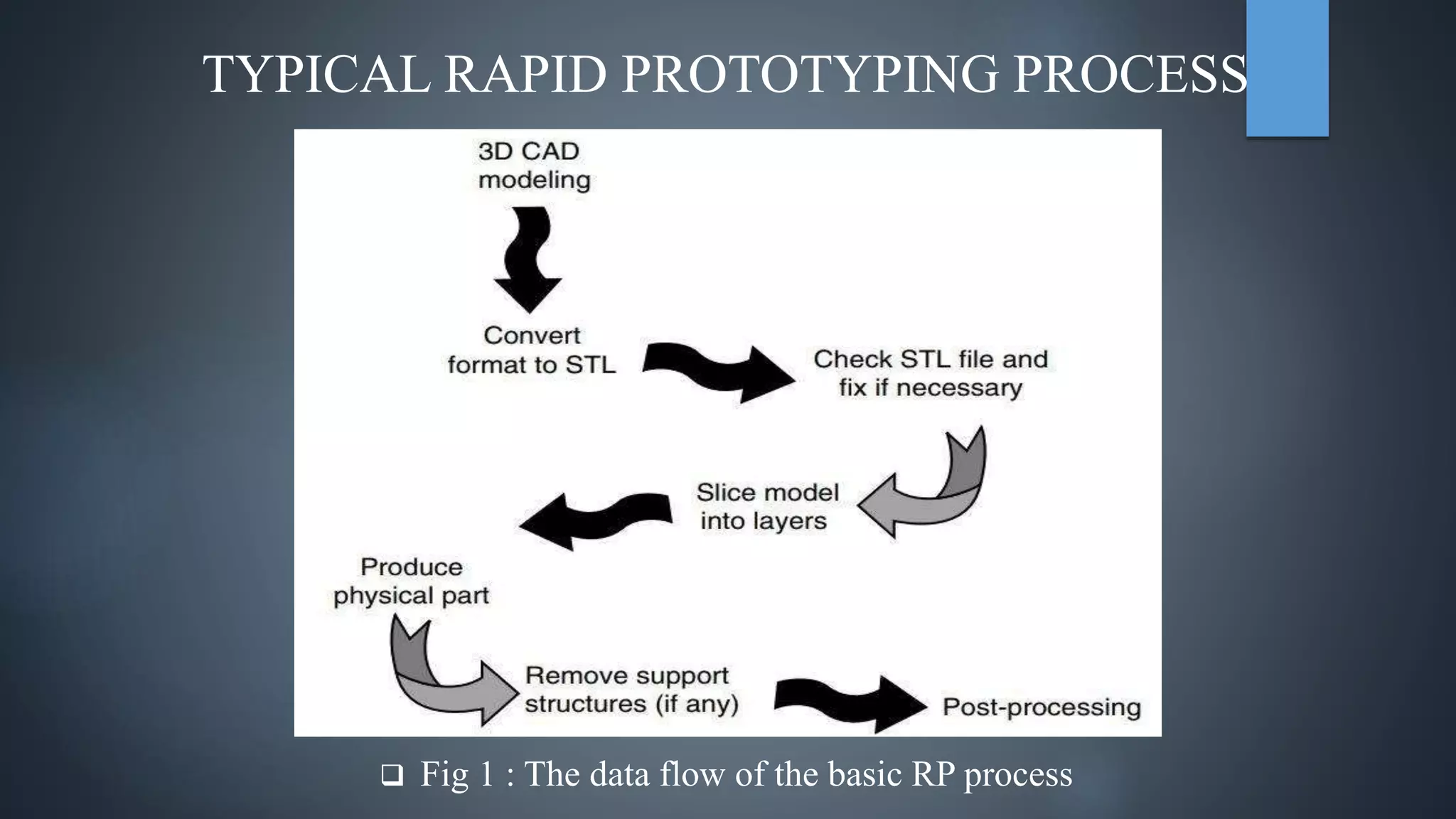
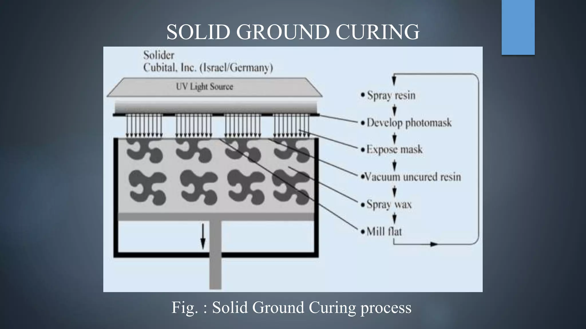
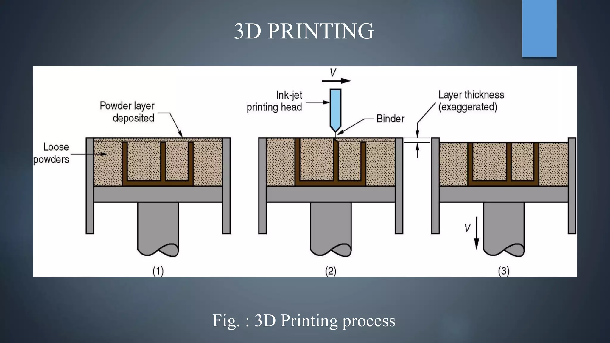
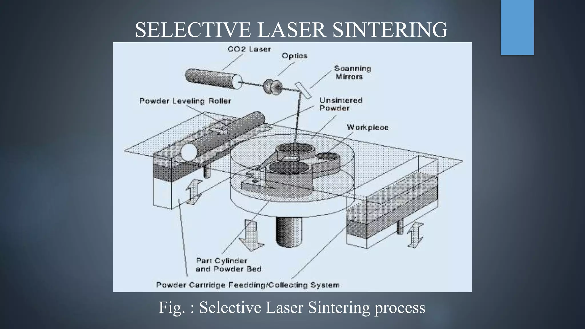
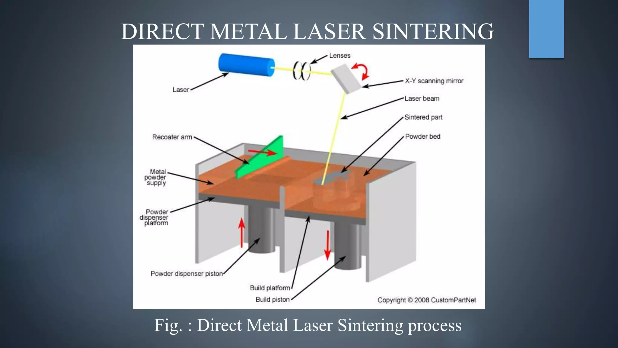
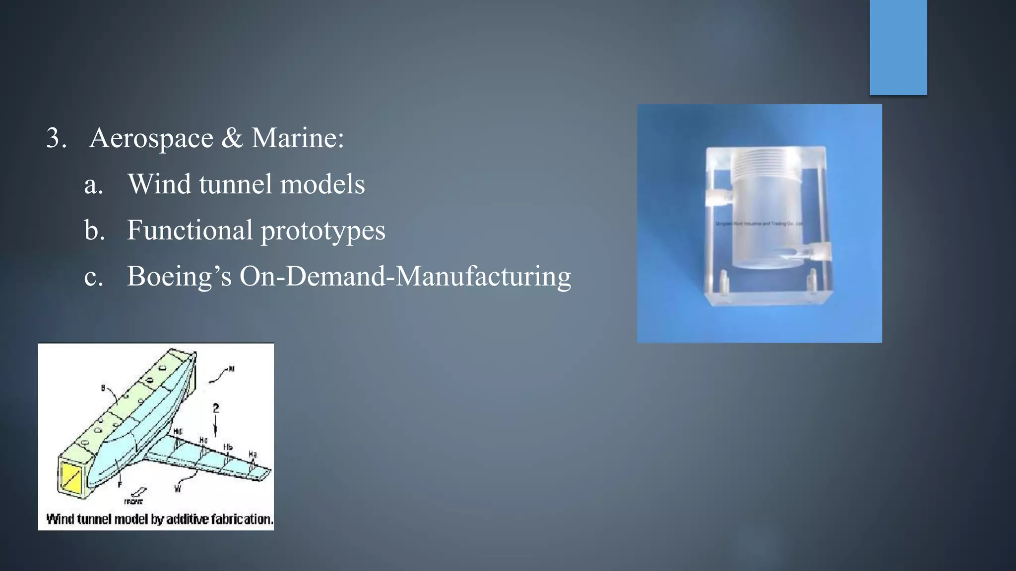
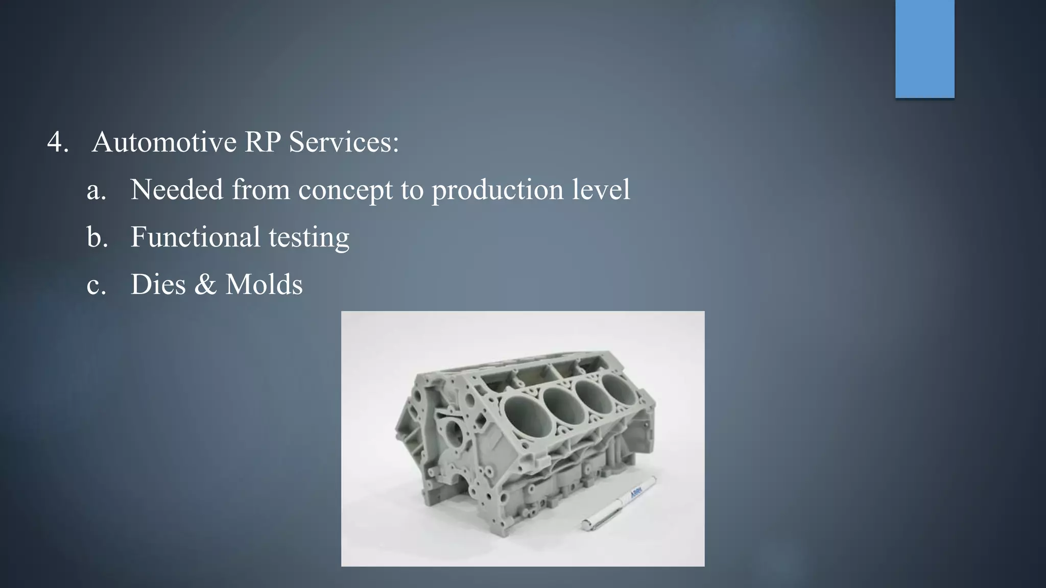
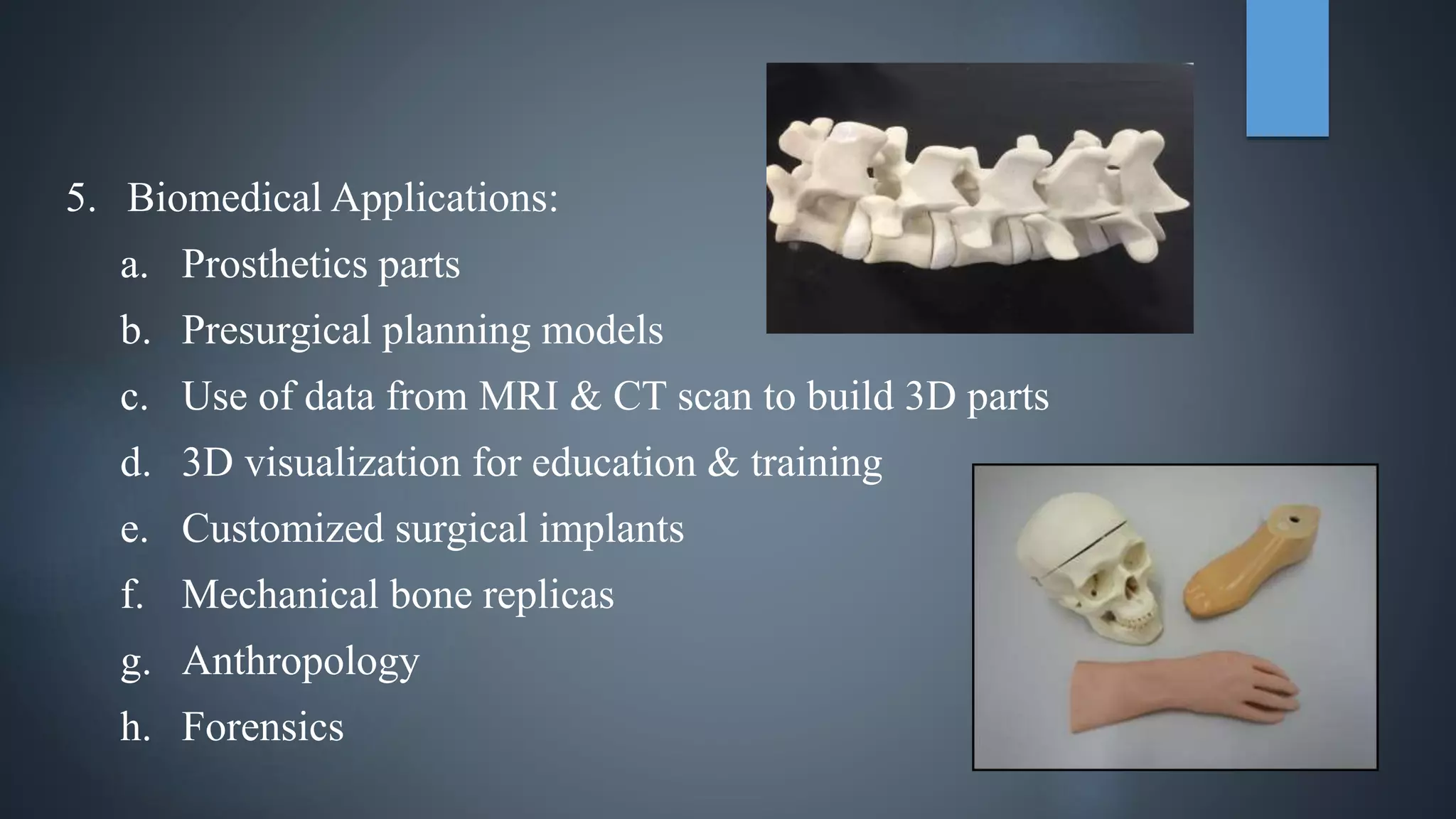
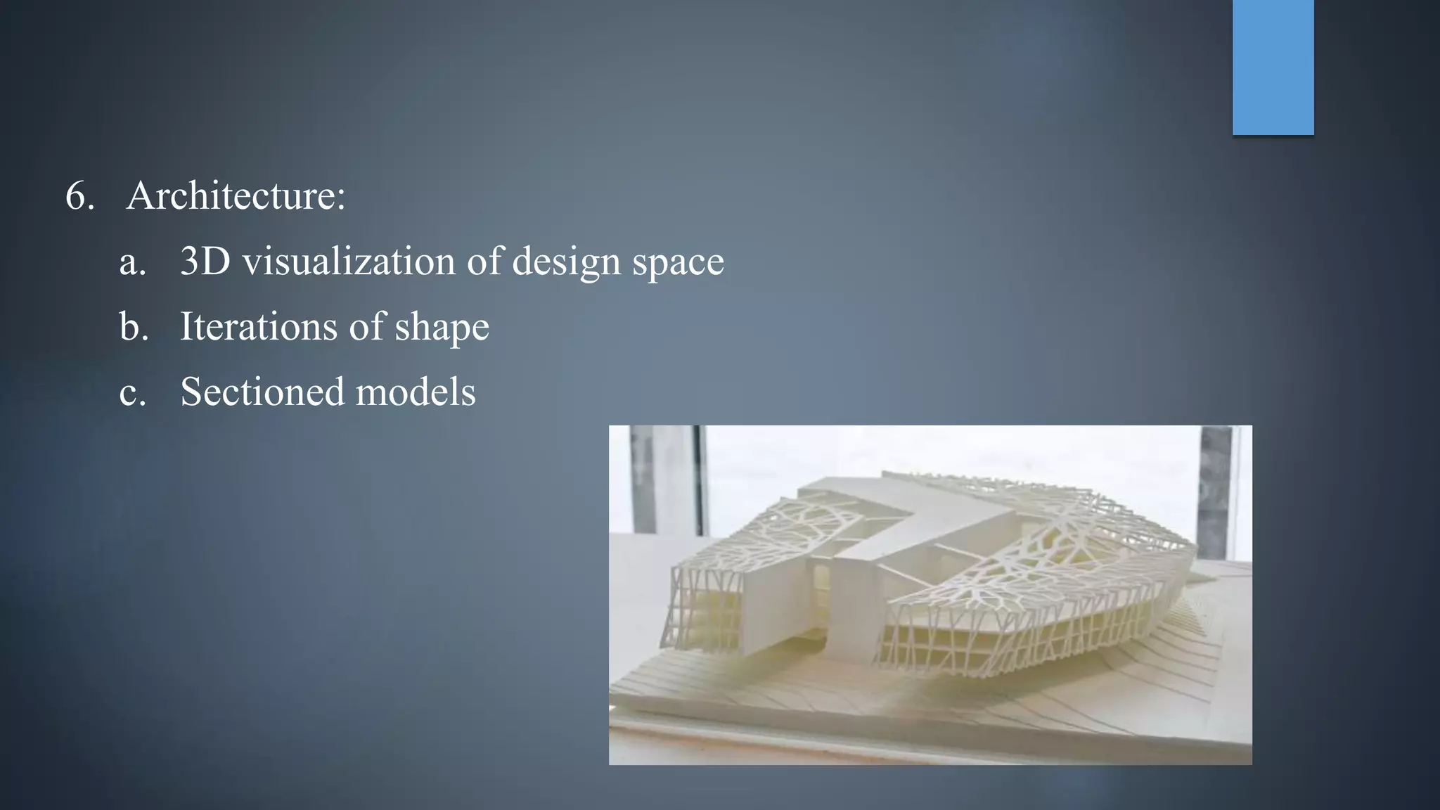
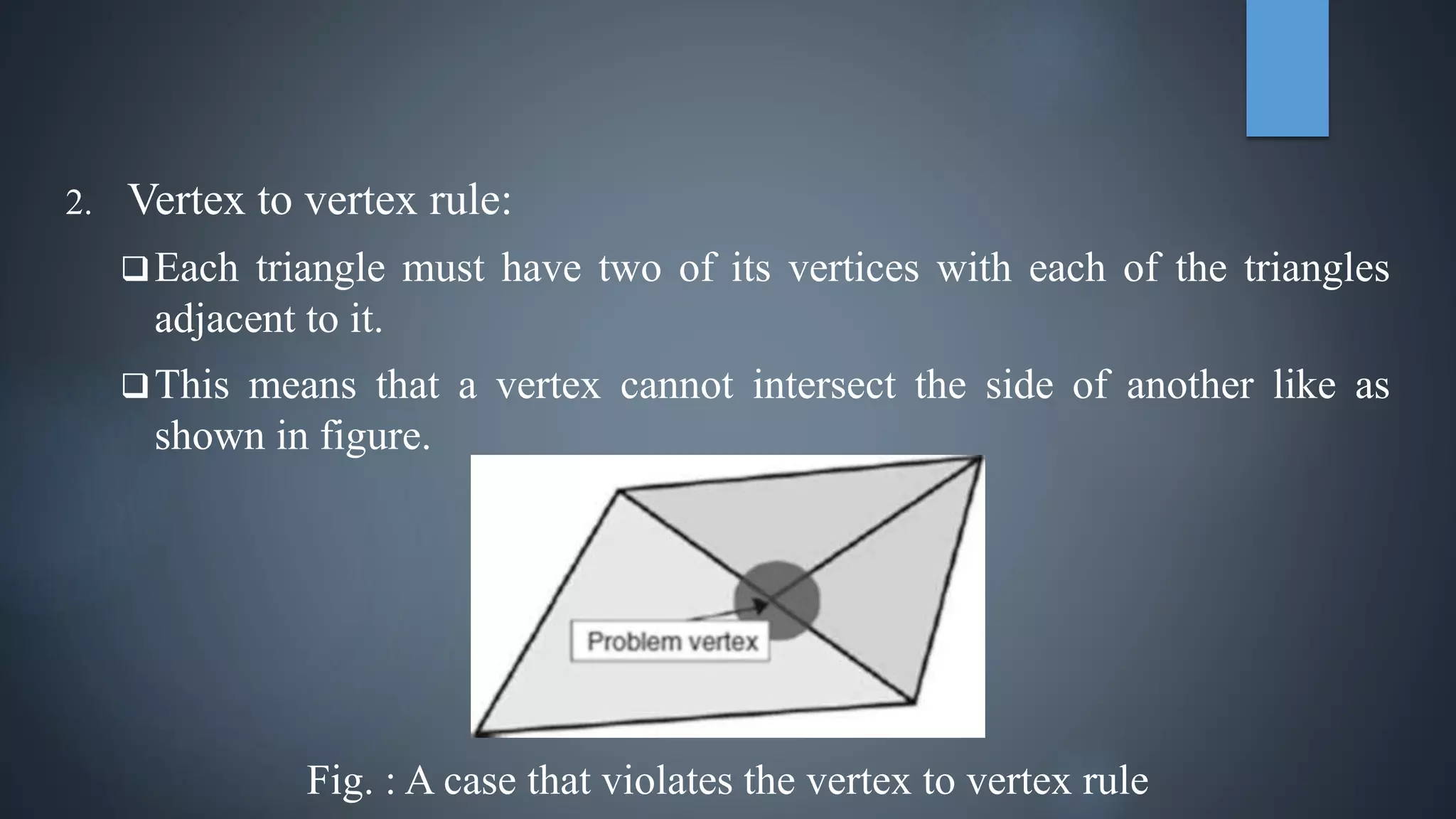
GOVERNMENT ENGINEERING COLLEGE DAHOD
MECHANICAL DEPARTMENT (M.E. – CAD/CAM)
 TOPIC: RAPID PROTOTYPING
 ENROLLMENT NO.: 180180708010
 PRESENTED BY: PITHVA MILAN R.
 GUIDED BY: PROF. M. Y. PATIL (HEAD OF DEPARTMENT)
INTRODUCTION
 The term rapid prototyping refers to a class of technologies that can
automatically construct physical models from Computer-Aided Design
(CAD) data.
 It is a process for rapidly creating a system or part representation before
final release or commercialization.
 It is a process for fabricating of a physical, 3-dimensional part of arbitrary
shape directly from a numerical description by a quick, totally automated
and highly flexible process.
TYPICAL RAPID PROTOTYPING PROCESS
 Fig 1 : The data flow of the basic RP process
CLASSIFICATION
 There are various ways to classify the RP techniques that have currently
been developed.
 The RP classification used here is based on the form of the starting
material:
1) Liquid Based RP Processes
2) Solid Based RP Processes
3) Powder Based RP Processes
LIQUID BASED RP PROCESSES
 Liquid based RP systems have the initial form of its material in liquid state.
 Through a process commonly known as curing, the liquid is converted into
solid state.
 Stereo-Lithography and Solid Ground Curing is liquid based rapid
prototyping process.
STEREOLITHOGRAPHY
Fig. : (1) At the start of the process, in which the initial layer is added to the
platform. (2) After several layers have been added so that the part geometry
gradually takes form.
 Stereo Lithography (SLA) is the best known rapid prototyping system. The
technique builds three-dimensional models from liquid photosensitive
polymers that solidify when exposed to laser beam. The model is built
upon a platform in a vat of photo sensitive liquid. A focused UV laser
traces out the first layer, solidifying the model cross section while leaving
excess areas liquid. In the next step, an elevator lowers the platform into
the liquid polymer by an amount equal to layer thickness. A sweeper
recoats the solidified layer with liquid, and the laser traces the second layer
on the first. This process is repeated until the prototype is complete.
Afterwards, the solid part is removed from the vat and rinsed clean of
excess liquid. Supports are broken off and the model is then placed in an
ultraviolet oven for complete curing.
ADVANTAGES
 Possibility of manufacturing parts which are impossible to produce
conventionally using a single process.
 Continuous unattended operation for 24 hours.
 High resolution.
 Any geometrical shape can be made with virtually no limitation.
DISADVANTAGES
 Necessity to have support structures
 Accuracy not in the range of mechanical part manufacturing.
 Restricted areas of application due to given material properties.
 Labour requirements for post processing, especially cleaning.
SOLID GROUND CURING
Fig. : Solid Ground Curing process
 Solid ground curing (SGC) is almost similar to Stereo-Lithography. In both
one uses ultraviolet light to selectively harden photosensitive polymers.
Unlike SLA, SGC cures an entire layer at a time. First, photosensitive resin
is sprayed on the build platform. Secondly, the machine develops a
photomask (like a stencil) of the layer to be built. This photomask is
printed on a glass plate above the build platform using an electrostatic
process similar to that found in photocopiers. The mask is then exposed to
UV light, which only passes through the transparent portions of the mask
to selectively harden the shape of the current layer. After the layer is cured,
the machine vacuums up the excess liquid resin and sprays wax in its place
to support the model during the build. The top surface is milled flat, and
then the process repeats to build the next layer. When the part is complete,
it must be de-waxed by immersing it in a solvent bath.
 Large parts, 500 × 500 × 350 mm, can be fabricated quickly.
 High speed allows production-like fabrication of many parts or large parts.
 Masks are created with laser printing-like process, then full layer exposed
at once.
 No post-cure required.
 Milling step ensures flatness for subsequent layer.
 Wax supports model: no extra supports needed.
ADVANTAGES
 Creates a lot of waste.
 Not as prevalent as SLA and SLS, but gaining ground because of the high
throughput and large parts
DISADVANTAGES
SOLID BASED RP PROCESSES
 Except for powder, solid-based RP systems are meant to encompass all
forms of material in the solid state.
 In this context, the solid form can include the shape in the form of a wire, a
roll, laminates & pallets.
 Fused Deposition Modeling(FDM) and Laminated Object
Manufacturing(LOM) are solid based rapid prototyping processes.
FUSED DEPOSITION MODELLING
Fig. : Fused Deposition Modelling process
 Fused Deposition Modeling (FDM) machine is basically a CNC-controlled
robot carrying a miniature extruder head. By feeding the head with a
plastic wire, solid objects are built "string by string". In this technique,
filaments of heated thermoplastic are extruded from a tip that moves in the
x-y plane. Like a baker decorating a cake, the controlled extrusion head
deposits very thin beads of material onto the build platform to form the
first layer. The platform is maintained at a lower temperature, so that the
thermoplastic quickly hardens. After the platform lowers, the extrusion
head deposits a second layer upon the first. Supports are built along the
way, fastened to the part either with a second, weaker material or with a
perforated junction.
ADVANTAGES
 Quick and cheap generation of models.
 Easy and convenient date building.
 No worry of possible exposure to toxic chemicals, lasers, or a liquid
polymer bath.
 No wastage of material during or after producing the model
 No requirement of clean-up.
 Quick change of materials
DISADVANTAGES
 Restricted accuracy due to the shape of the material used: wire of 1.27 mm
diameter.
LAMINATED OBJECT MANUFACTURING
Fig. : Schematic of the Laminated Object Manufacturing process
 In this technique, layers of adhesive-coated sheet material are bonded
together to form a prototype. The original material consists of paper
laminated with heat-activated glue and rolled up on spools. A
feeder/collector mechanism advances the sheet over the build platform,
where a base has been constructed from paper and double-sided foam tape.
In the next stage, a heated roller applies pressure to bond the paper to the
base. A focused laser cuts the outline of the first layer into the paper and
then cross-hatches the excess area (the negative space in the prototype).
Cross-hatching breaks up the extra material, making it easier to remove
during post-processing.
 During the build, the excess material provides excellent support for
overhangs and thin-walled sections. After the first layer is cut, the platform
lowers out of the way and fresh material is advanced. The platform rises
slightly below the previous height, the roller bonds the second layer to the
first, and the laser cuts the second layer. This process is repeated as needed
to build the part, which will have a wood-like texture. Because the models
are made of paper, they must be sealed and finished with paint or varnish
to prevent moisture damage.
ADVANTAGES
 Variety of organic and inorganic materials can be used such as paper,
plastic, ceramic, composite, etc.
 Relatively low costs
 Much faster process than competitive techniques
 Virtually produces no internal stress and associated undesirable
deformation.
 Robust capacity of dealing with imperfect STL files, created with
discontinuities,
 Best suited for building large parts, as if the machine with the largest
workspace on the market today.
DISADVANTAGES
 Limited stability of the objects due to the bonding strength of the glued
layers.
 Not well suited for manufacturing parts with thin walls in the z-direction
 Hollow parts, like bottles, can not be built.
POWDER BASED RP PROCESSES
 In a strict sense, powder is by-and-large in the solid state.
 However, it is intentionally created as a category outside the solid-based
RP systems to mean powder in grain-like form.
 This type of RP systems employ the Joining/Binding method.
 The method of joining/binding differs for liquid-based and solid-based
systems.
 3D printing, Selective Laser Sintering(SLS), Direct Metal Laser
Sintering(DMLS) are powder based rapid prototyping processes.
3D PRINTING
Fig. : 3D Printing process
 Part is built layer-by-layer using an ink-jet printer to eject adhesive
bonding material onto successive layers of powders
 Binder is deposited in areas corresponding to the cross sections of part, as
determined by slicing the CAD geometric model into layers
 The binder holds the powders together to form the solid part, while the
unbonded powders remain loose to be removed later
 To further strengthen the part, a sintering step can be applied to bond the
individual powders
SELECTIVE LASER SINTERING
Fig. : Selective Laser Sintering process
 Selective Laser Sintering (SLS) is a 3-dimensional printing process based
on sintering, using a laser beam directed by a computer onto the surface of
metallic or non-metallic powders selectively to produce copies of solid or
surface models.
 The process operates on the layer-by-layer principle. At the beginning a
very thin layer of heat fusible powder is deposited in the working space
container. The CO2 laser sinters the powders.
 The sintering process uses the laser to raise the temperature of the powder
to a point of fusing without actually melting it.
 As the process is repeated, layers of powder are deposited and sintered
until the object is complete.
 The powder is transferred from the powder cartridge feeding system to the
part cylinder (the working space container) via a counter rolling cylinder, a
scraper blade or a slot feeder.
 In the unsintered areas, powder remains loose and serves as natural support
for the next layer of powder and object under fabrication. No additional
support structure is required.
ADVANTAGES
 Virtually any materials that have decreased viscosity upon heating can
potentially be used.
 Do not require any post-curing except when ceramics are used.
 No need to create a support structure, which saves time.
 Advanced softwares allowing concurrent slicing of the part geometry files
while processing the object.
DISADVANTAGES
 Raw appearance on the part surface due to hardening of additional powder
on the borderline of the object.
 Necessity to provide the process chamber continuously with nitrogen to
assure safe material sintering.
 Careful handling of toxic gases emitted from the fusing process.
DIRECT METAL LASER SINTERING
Fig. : Direct Metal Laser Sintering process
 Direct metal laser sintering is an additive manufacturing technique that
uses a laser as the power source to sinter powdered material, aiming the
laser automatically at points in space defined by a 3D model, binding the
material together to create a solid structure.
 Metal powders used in this process are Stainless steel 17-4, Aluminium &
Titanium Ti-64.
ADVANTAGES
 High Speed: Because no special tooling is required, parts can be built in a
matter of hours.
 Complex geometries: Components can be designed with internal features
and passages that cannot be cast or otherwise machined.
 High quality: DMLS creates parts with high accuracy and detailed
resolution.
DISADVANTAGES
 Surfaces need to be polished.
 Removing metal support structures and thermal post-processing is time
consuming.
APPLICATION OF RAPID PROTOTYPING
1. Rapid Tooling:
a. Pattern for Sand Casting
b. Pattern for Investment Casting
c. Pattern for Injection moldings
(a) (b) (c)
2. Rapid Manufacturing:
a. Short productions runs
b. Custom made parts
c. On-Demand Manufacturing
d. Manufacturing of very complex shapes
3. Aerospace & Marine:
a. Wind tunnel models
b. Functional prototypes
c. Boeing’s On-Demand-Manufacturing
4. Automotive RP Services:
a. Needed from concept to production level
b. Functional testing
c. Dies & Molds
5. Biomedical Applications:
a. Prosthetics parts
b. Presurgical planning models
c. Use of data from MRI & CT scan to build 3D parts
d. 3D visualization for education & training
e. Customized surgical implants
f. Mechanical bone replicas
g. Anthropology
h. Forensics
6. Architecture:
a. 3D visualization of design space
b. Iterations of shape
c. Sectioned models
7. Fashion & Jewelry:
a. Shoe Design
b. Jewelry
c. Pattern for lost wax
d. Other castings
8. Sculptures:
a. 3D scanning
b. Layered fabrication
c. Replicas
d. Original work
STL FORMAT
 The STL is a abbreviation for “Standard Triangulated Language”.
 Through software, the developed CAD model is converted into the form of
millions of small triangles.
 This later helps in storing and conversion of data.
PROBLEM WITH STL FILE
 The STL format is quite simple, there can still be errors in files resulting
from CAD conversion.
 The following are typical problems that can occur in bad STL files.
1. Unit Changing:
This is not strictly a result of a bad STL file.
US machines still commonly use imperial measurements and the rest of
the world uses metric. So, some files can appear scaled because there is
no explicit mention of the units used in the STL format.
If the person building the model is unaware of the purpose of the part
then he may build it approximately 25 times too large or too small in
one direction.
2. Vertex to vertex rule:
Each triangle must have two of its vertices with each of the triangles
adjacent to it.
This means that a vertex cannot intersect the side of another like as
shown in figure.
Fig. : A case that violates the vertex to vertex rule
3. Leaking STL files:
STL files should describe fully enclosed surfaces that represent the
solids generated within the originating CAD system.
or
In other words, STL data files should construct one or more manifold
entities according to Euler’s Rule for solids:
No. of faces – No. of edges + No. of vertices = 2×No. of bodies
If this rule does not hold then the STL file is said to be leaking and the
file slices will not represent the actual model.
There may be too few or too many vectors for a particular slice.
4. Degenerated facets:
These facets normally result from numerical truncation. A triangle may
be so small that all three points virtually coincide with each other.
After truncation, these points lay on top of each other causing a triangle
with no area. This can also occur when a truncated triangle returns no
height and all three vertices of the triangle lie on a single straight line.
While the resulting slicing algorithm will not cause incorrect slices,
there may be some difficulties with any checking algorithms and so such
triangles should really be removed from the STL file.

180180708010 - RAPID PROTOTYPING

  • 1.
    GOVERNMENT ENGINEERING COLLEGEDAHOD MECHANICAL DEPARTMENT (M.E. – CAD/CAM)  TOPIC: RAPID PROTOTYPING  ENROLLMENT NO.: 180180708010  PRESENTED BY: PITHVA MILAN R.  GUIDED BY: PROF. M. Y. PATIL (HEAD OF DEPARTMENT)
  • 2.
    INTRODUCTION  The termrapid prototyping refers to a class of technologies that can automatically construct physical models from Computer-Aided Design (CAD) data.  It is a process for rapidly creating a system or part representation before final release or commercialization.  It is a process for fabricating of a physical, 3-dimensional part of arbitrary shape directly from a numerical description by a quick, totally automated and highly flexible process.
  • 3.
    TYPICAL RAPID PROTOTYPINGPROCESS  Fig 1 : The data flow of the basic RP process
  • 4.
    CLASSIFICATION  There arevarious ways to classify the RP techniques that have currently been developed.  The RP classification used here is based on the form of the starting material: 1) Liquid Based RP Processes 2) Solid Based RP Processes 3) Powder Based RP Processes
  • 5.
    LIQUID BASED RPPROCESSES  Liquid based RP systems have the initial form of its material in liquid state.  Through a process commonly known as curing, the liquid is converted into solid state.  Stereo-Lithography and Solid Ground Curing is liquid based rapid prototyping process.
  • 6.
    STEREOLITHOGRAPHY Fig. : (1)At the start of the process, in which the initial layer is added to the platform. (2) After several layers have been added so that the part geometry gradually takes form.
  • 7.
     Stereo Lithography(SLA) is the best known rapid prototyping system. The technique builds three-dimensional models from liquid photosensitive polymers that solidify when exposed to laser beam. The model is built upon a platform in a vat of photo sensitive liquid. A focused UV laser traces out the first layer, solidifying the model cross section while leaving excess areas liquid. In the next step, an elevator lowers the platform into the liquid polymer by an amount equal to layer thickness. A sweeper recoats the solidified layer with liquid, and the laser traces the second layer on the first. This process is repeated until the prototype is complete. Afterwards, the solid part is removed from the vat and rinsed clean of excess liquid. Supports are broken off and the model is then placed in an ultraviolet oven for complete curing.
  • 8.
    ADVANTAGES  Possibility ofmanufacturing parts which are impossible to produce conventionally using a single process.  Continuous unattended operation for 24 hours.  High resolution.  Any geometrical shape can be made with virtually no limitation.
  • 9.
    DISADVANTAGES  Necessity tohave support structures  Accuracy not in the range of mechanical part manufacturing.  Restricted areas of application due to given material properties.  Labour requirements for post processing, especially cleaning.
  • 10.
    SOLID GROUND CURING Fig.: Solid Ground Curing process
  • 11.
     Solid groundcuring (SGC) is almost similar to Stereo-Lithography. In both one uses ultraviolet light to selectively harden photosensitive polymers. Unlike SLA, SGC cures an entire layer at a time. First, photosensitive resin is sprayed on the build platform. Secondly, the machine develops a photomask (like a stencil) of the layer to be built. This photomask is printed on a glass plate above the build platform using an electrostatic process similar to that found in photocopiers. The mask is then exposed to UV light, which only passes through the transparent portions of the mask to selectively harden the shape of the current layer. After the layer is cured, the machine vacuums up the excess liquid resin and sprays wax in its place to support the model during the build. The top surface is milled flat, and then the process repeats to build the next layer. When the part is complete, it must be de-waxed by immersing it in a solvent bath.
  • 12.
     Large parts,500 × 500 × 350 mm, can be fabricated quickly.  High speed allows production-like fabrication of many parts or large parts.  Masks are created with laser printing-like process, then full layer exposed at once.  No post-cure required.  Milling step ensures flatness for subsequent layer.  Wax supports model: no extra supports needed. ADVANTAGES
  • 13.
     Creates alot of waste.  Not as prevalent as SLA and SLS, but gaining ground because of the high throughput and large parts DISADVANTAGES
  • 14.
    SOLID BASED RPPROCESSES  Except for powder, solid-based RP systems are meant to encompass all forms of material in the solid state.  In this context, the solid form can include the shape in the form of a wire, a roll, laminates & pallets.  Fused Deposition Modeling(FDM) and Laminated Object Manufacturing(LOM) are solid based rapid prototyping processes.
  • 15.
    FUSED DEPOSITION MODELLING Fig.: Fused Deposition Modelling process
  • 16.
     Fused DepositionModeling (FDM) machine is basically a CNC-controlled robot carrying a miniature extruder head. By feeding the head with a plastic wire, solid objects are built "string by string". In this technique, filaments of heated thermoplastic are extruded from a tip that moves in the x-y plane. Like a baker decorating a cake, the controlled extrusion head deposits very thin beads of material onto the build platform to form the first layer. The platform is maintained at a lower temperature, so that the thermoplastic quickly hardens. After the platform lowers, the extrusion head deposits a second layer upon the first. Supports are built along the way, fastened to the part either with a second, weaker material or with a perforated junction.
  • 17.
    ADVANTAGES  Quick andcheap generation of models.  Easy and convenient date building.  No worry of possible exposure to toxic chemicals, lasers, or a liquid polymer bath.  No wastage of material during or after producing the model  No requirement of clean-up.  Quick change of materials
  • 18.
    DISADVANTAGES  Restricted accuracydue to the shape of the material used: wire of 1.27 mm diameter.
  • 19.
    LAMINATED OBJECT MANUFACTURING Fig.: Schematic of the Laminated Object Manufacturing process
  • 20.
     In thistechnique, layers of adhesive-coated sheet material are bonded together to form a prototype. The original material consists of paper laminated with heat-activated glue and rolled up on spools. A feeder/collector mechanism advances the sheet over the build platform, where a base has been constructed from paper and double-sided foam tape. In the next stage, a heated roller applies pressure to bond the paper to the base. A focused laser cuts the outline of the first layer into the paper and then cross-hatches the excess area (the negative space in the prototype). Cross-hatching breaks up the extra material, making it easier to remove during post-processing.
  • 21.
     During thebuild, the excess material provides excellent support for overhangs and thin-walled sections. After the first layer is cut, the platform lowers out of the way and fresh material is advanced. The platform rises slightly below the previous height, the roller bonds the second layer to the first, and the laser cuts the second layer. This process is repeated as needed to build the part, which will have a wood-like texture. Because the models are made of paper, they must be sealed and finished with paint or varnish to prevent moisture damage.
  • 22.
    ADVANTAGES  Variety oforganic and inorganic materials can be used such as paper, plastic, ceramic, composite, etc.  Relatively low costs  Much faster process than competitive techniques  Virtually produces no internal stress and associated undesirable deformation.  Robust capacity of dealing with imperfect STL files, created with discontinuities,  Best suited for building large parts, as if the machine with the largest workspace on the market today.
  • 23.
    DISADVANTAGES  Limited stabilityof the objects due to the bonding strength of the glued layers.  Not well suited for manufacturing parts with thin walls in the z-direction  Hollow parts, like bottles, can not be built.
  • 24.
    POWDER BASED RPPROCESSES  In a strict sense, powder is by-and-large in the solid state.  However, it is intentionally created as a category outside the solid-based RP systems to mean powder in grain-like form.  This type of RP systems employ the Joining/Binding method.  The method of joining/binding differs for liquid-based and solid-based systems.  3D printing, Selective Laser Sintering(SLS), Direct Metal Laser Sintering(DMLS) are powder based rapid prototyping processes.
  • 25.
    3D PRINTING Fig. :3D Printing process
  • 26.
     Part isbuilt layer-by-layer using an ink-jet printer to eject adhesive bonding material onto successive layers of powders  Binder is deposited in areas corresponding to the cross sections of part, as determined by slicing the CAD geometric model into layers  The binder holds the powders together to form the solid part, while the unbonded powders remain loose to be removed later  To further strengthen the part, a sintering step can be applied to bond the individual powders
  • 27.
    SELECTIVE LASER SINTERING Fig.: Selective Laser Sintering process
  • 28.
     Selective LaserSintering (SLS) is a 3-dimensional printing process based on sintering, using a laser beam directed by a computer onto the surface of metallic or non-metallic powders selectively to produce copies of solid or surface models.  The process operates on the layer-by-layer principle. At the beginning a very thin layer of heat fusible powder is deposited in the working space container. The CO2 laser sinters the powders.  The sintering process uses the laser to raise the temperature of the powder to a point of fusing without actually melting it.  As the process is repeated, layers of powder are deposited and sintered until the object is complete.
  • 29.
     The powderis transferred from the powder cartridge feeding system to the part cylinder (the working space container) via a counter rolling cylinder, a scraper blade or a slot feeder.  In the unsintered areas, powder remains loose and serves as natural support for the next layer of powder and object under fabrication. No additional support structure is required.
  • 30.
    ADVANTAGES  Virtually anymaterials that have decreased viscosity upon heating can potentially be used.  Do not require any post-curing except when ceramics are used.  No need to create a support structure, which saves time.  Advanced softwares allowing concurrent slicing of the part geometry files while processing the object.
  • 31.
    DISADVANTAGES  Raw appearanceon the part surface due to hardening of additional powder on the borderline of the object.  Necessity to provide the process chamber continuously with nitrogen to assure safe material sintering.  Careful handling of toxic gases emitted from the fusing process.
  • 32.
    DIRECT METAL LASERSINTERING Fig. : Direct Metal Laser Sintering process
  • 33.
     Direct metallaser sintering is an additive manufacturing technique that uses a laser as the power source to sinter powdered material, aiming the laser automatically at points in space defined by a 3D model, binding the material together to create a solid structure.  Metal powders used in this process are Stainless steel 17-4, Aluminium & Titanium Ti-64.
  • 34.
    ADVANTAGES  High Speed:Because no special tooling is required, parts can be built in a matter of hours.  Complex geometries: Components can be designed with internal features and passages that cannot be cast or otherwise machined.  High quality: DMLS creates parts with high accuracy and detailed resolution.
  • 35.
    DISADVANTAGES  Surfaces needto be polished.  Removing metal support structures and thermal post-processing is time consuming.
  • 36.
    APPLICATION OF RAPIDPROTOTYPING 1. Rapid Tooling: a. Pattern for Sand Casting b. Pattern for Investment Casting c. Pattern for Injection moldings (a) (b) (c)
  • 37.
    2. Rapid Manufacturing: a.Short productions runs b. Custom made parts c. On-Demand Manufacturing d. Manufacturing of very complex shapes
  • 38.
    3. Aerospace &Marine: a. Wind tunnel models b. Functional prototypes c. Boeing’s On-Demand-Manufacturing
  • 39.
    4. Automotive RPServices: a. Needed from concept to production level b. Functional testing c. Dies & Molds
  • 40.
    5. Biomedical Applications: a.Prosthetics parts b. Presurgical planning models c. Use of data from MRI & CT scan to build 3D parts d. 3D visualization for education & training e. Customized surgical implants f. Mechanical bone replicas g. Anthropology h. Forensics
  • 41.
    6. Architecture: a. 3Dvisualization of design space b. Iterations of shape c. Sectioned models
  • 42.
    7. Fashion &Jewelry: a. Shoe Design b. Jewelry c. Pattern for lost wax d. Other castings
  • 43.
    8. Sculptures: a. 3Dscanning b. Layered fabrication c. Replicas d. Original work
  • 44.
    STL FORMAT  TheSTL is a abbreviation for “Standard Triangulated Language”.  Through software, the developed CAD model is converted into the form of millions of small triangles.  This later helps in storing and conversion of data.
  • 45.
    PROBLEM WITH STLFILE  The STL format is quite simple, there can still be errors in files resulting from CAD conversion.  The following are typical problems that can occur in bad STL files.
  • 46.
    1. Unit Changing: Thisis not strictly a result of a bad STL file. US machines still commonly use imperial measurements and the rest of the world uses metric. So, some files can appear scaled because there is no explicit mention of the units used in the STL format. If the person building the model is unaware of the purpose of the part then he may build it approximately 25 times too large or too small in one direction.
  • 47.
    2. Vertex tovertex rule: Each triangle must have two of its vertices with each of the triangles adjacent to it. This means that a vertex cannot intersect the side of another like as shown in figure. Fig. : A case that violates the vertex to vertex rule
  • 48.
    3. Leaking STLfiles: STL files should describe fully enclosed surfaces that represent the solids generated within the originating CAD system. or In other words, STL data files should construct one or more manifold entities according to Euler’s Rule for solids: No. of faces – No. of edges + No. of vertices = 2×No. of bodies If this rule does not hold then the STL file is said to be leaking and the file slices will not represent the actual model. There may be too few or too many vectors for a particular slice.
  • 49.
    4. Degenerated facets: Thesefacets normally result from numerical truncation. A triangle may be so small that all three points virtually coincide with each other. After truncation, these points lay on top of each other causing a triangle with no area. This can also occur when a truncated triangle returns no height and all three vertices of the triangle lie on a single straight line. While the resulting slicing algorithm will not cause incorrect slices, there may be some difficulties with any checking algorithms and so such triangles should really be removed from the STL file.