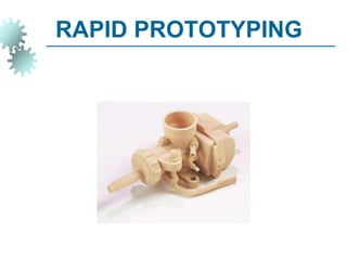
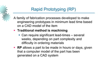
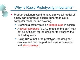
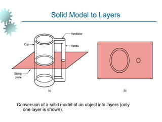
SlideShare a Scribd company logo
RAPID PROTOTYPING
Objective
1. Fundamentals of Rapid Prototyping
2. Rapid Prototyping Technologies
3. Applications and Benefits of Rapid Prototyping
4. Material of RP
5. Process sequence of RP
6. Method of manufacturing of RP
Rapid Prototyping (RP)
A family of fabrication processes developed to make
engineering prototypes in minimum lead time based
on a CAD model of the item
 Traditional method is machining
 Can require significant lead-times – several
weeks, depending on part complexity and
difficulty in ordering materials
 RP allows a part to be made in hours or days, given
that a computer model of the part has been
generated on a CAD system
Why is Rapid Prototyping Important?
 Product designers want to have a physical model of
a new part or product design rather than just a
computer model or line drawing
 Creating a prototype is an integral step in design
 A virtual prototype (a CAD model of the part) may
not be sufficient for the designer to visualize the
part adequately
 Using RP to make the prototype, the designer
can see and feel the part and assess its merits
and shortcomings
RP – Two Basic Categories:
1. Material removal RP - machining, using a
dedicated CNC machine that is available to the
design department on short notice
 Starting material is often wax
 Easy to machine
 Can be melted and resolidified
 The CNC machines are often small - called
desktop machining
2. Material addition RP - adds layers of material one
at a time to build the solid part from bottom to top
Starting Materials in Material Addition RP
1. Liquid monomers that are cured layer by layer into solid
polymers
2. Powders that are aggregated and bonded layer by layer
3. Solid sheets that are laminated to create the solid part
Additional Methods
 In addition to starting material, the various material
addition RP technologies use different methods of
building and adding layers to create the solid part
 There is a correlation between starting material
and part building techniques
Steps to Prepare Control Instructions
1. Geometric modeling - model the component on a
CAD system to define its enclosed volume
2. Tessellation of the geometric model - the CAD
model is converted into a computerized format that
approximates its surfaces by facets (triangles or
polygons)
3. Slicing of the model into layers - computerized
model is sliced into closely-spaced parallel
horizontal layers
CAD Part and Tessellation
CAD Part Tessellation
Conversion of a solid model of an object into layers (only
one layer is shown).
Solid Model to Layers
More About Rapid Prototyping
 Alternative names for RP:
 Layer manufacturing
 Direct CAD manufacturing
 Solid freeform fabrication
 Rapid prototyping and manufacturing (RPM)
 RP technologies are being used increasingly to
make production parts and production tooling, not
just prototypes
Classification of RP Technologies
 There are various ways to classify the RP
techniques that have currently been developed
 The RP classification used here is based on the
form of the starting material:
1. Liquid-based
2. Solid-based
3. Powder-based
1- Liquid-Based Rapid Prototyping Systems
 Starting material is a liquid
 About a dozen RP technologies are in this category
 Includes the following processes:
1.1 Stereolithography
1.2 Solid ground curing
1.3 Droplet deposition manufacturing
1.1-Stereolithography (STL)
RP process for fabricating a solid plastic part out of a
photosensitive liquid polymer using a directed laser
beam to solidify the polymer
 Part fabrication is accomplished as a series of layers
- each layer is added onto the previous layer to
gradually build the 3-D geometry
 The first addition RP technology - introduced 1988
by 3D Systems Inc. based on the work of Charles
Hull
 More installations than any other RP method
Stereolithography: (1) at the start of the process, in which the initial layer
is added to the platform; and (2) after several layers have been added
so that the part geometry gradually takes form.
Stereolithography
A part produced by stereolithography
Facts about STL
 Each layer is 0.076 mm to 0.50 mm (0.003 in to
0.020 in.) thick
 Thinner layers provide better resolution and more
intricate shapes; but processing time is longer
 Starting materials are liquid monomers
 Polymerization occurs on exposure to UV light
produced by laser scanning beam
 Scanning speeds ~ 500 to 2500 mm/s
Part Build Time in STL
Time to complete a single layer :
where Ti = time to complete layer i; Ai = area of
layer i; v = average scanning speed of the laser
beam at the surface; D = diameter of the “spot
size,” assumed circular; and Td = delay time
between layers to reposition the worktable
d
i
i T
vD
A
T 

Part Build Time in STL - continued
Once the Ti values have been determined for all layers,
then the build cycle time is:
where Tc = STL build cycle time; and nl =
number of layers used to approximate the part
 Time to build a part ranges from one hour for
small parts of simple geometry up to several
dozen hours for complex parts



i
n
i
i
c T
T
1
1.2- Solid Ground Curing (SGC)
Like stereolithography, SGC works by curing a
photosensitive polymer layer by layer to create a
solid model based on CAD geometric data
 Instead of using a scanning laser beam to cure a
given layer, the entire layer is exposed to a UV
source through a mask above the liquid polymer
 Hardening takes 2 to 3 s for each layer
Figure 34.4 SGC
steps for each
layer: (1) mask
preparation, (2)
applying liquid
photopolymer
layer,(3) mask
positioning and
exposure of layer,
(4) uncured
polymer removed
from surface, (5)
wax filling, (6)
milling for flatness
and thickness.
Solid Ground Curing
Facts about SGC
 Sequence for each layer takes about 90 seconds
 Time to produce a part by SGC is claimed to be
about eight times faster than other RP systems
 The solid cubic form created in SGC consists of solid
polymer and wax
 The wax provides support for fragile and
overhanging features of the part during fabrication,
but can be melted away later to leave the free-
standing part
1.3- Droplet Deposition Manufacturing (DDM)
Starting material is melted and small droplets are shot
by a nozzle onto previously formed layer
 Droplets cold weld to surface to form a new layer
 Deposition for each layer controlled by a moving x-y
nozzle whose path is based on a cross section of a
CAD geometric model that is sliced into layers
 Work materials include wax and thermoplastics
Droplet Deposition Manufacturing (DDM)
2- Solid-Based Rapid Prototyping Systems
 Starting material is a solid
 Solid-based RP systems include the following
processes:
2.1- Laminated object manufacturing
2.2- Fused deposition modeling
2.1- Laminated Object Manufacturing (LOM)
Solid physical model made by stacking layers of sheet
stock, each an outline of the cross-sectional shape
of a CAD model that is sliced into layers
 Starting sheet stock includes paper, plastic,
cellulose, metals, or fiber-reinforced materials
 The sheet is usually supplied with adhesive backing
as rolls that are spooled between two reels
 After cutting, excess material in the layer remains in
place to support the part during building
Figure 34.5 Laminated object manufacturing.
Laminated Object Manufacturing
2.2- Fused Deposition Modeling (FDM)
RP process in which a long filament of wax or polymer
is extruded onto existing part surface from a
workhead to complete each new layer
 Workhead is controlled in the x-y plane during each
layer and then moves up by a distance equal to one
layer in the z-direction
 Extrudate is solidified and cold welded to the cooler
part surface in about 0.1 s
 Part is fabricated from the base up, using a layer-by-
layer procedure
3- Powder-Based RP Systems
 Starting material is a powder
 Powder-based RP systems include the following:
3.1- Selective laser sintering
3.2- Three dimensional printing
3.1- Selective Laser Sintering (SLS)
Moving laser beam sinters heat-fusible powders in
areas corresponding to the CAD geometry model
one layer at a time to build the solid part
 After each layer is completed, a new layer of loose
powders is spread across the surface
 Layer by layer, the powders are gradually bonded by
the laser beam into a solid mass that forms the 3-D
part geometry
 In areas not sintered, the powders are loose and can
be poured out of completed part
3.2- Three Dimensional Printing (3DP)
Part is built layer-by-layer using an ink-jet printer to
eject adhesive bonding material onto successive
layers of powders
 Binder is deposited in areas corresponding to the
cross sections of part, as determined by slicing the
CAD geometric model into layers
 The binder holds the powders together to form the
solid part, while the unbonded powders remain loose
to be removed later
 To further strengthen the part, a sintering step can
be applied to bond the individual powders
Figure 34.6 Three dimensional printing: (1) powder layer is
deposited, (2) ink-jet printing of areas that will become the part,
and (3) piston is lowered for next layer (key: v = motion).
Three Dimensional Printing
RP Applications
 Applications of rapid prototyping can be classified
into three categories:
1. Design
2. Engineering analysis and planning
3. Tooling and manufacturing
Design Applications
 Designers are able to confirm their design by
building a real physical model in minimum time using
RP
 Design benefits of RP:
 Reduced lead times to produce prototypes
 Improved ability to visualize part geometry
 Early detection of design errors
 Increased capability to compute mass properties
Engineering Analysis and Planning
 Existence of part allows certain engineering analysis
and planning activities to be accomplished that
would be more difficult without the physical entity
 Comparison of different shapes and styles to
determine aesthetic appeal
 Wind tunnel testing of streamline shapes
 Stress analysis of physical model
 Fabrication of pre-production parts for process
planning and tool design
Tooling Applications
 Called rapid tool making (RTM) when RP is used to
fabricate production tooling
 Two approaches for tool-making:
1. Indirect RTM method
2. Direct RTM method
Indirect RTM Method
Pattern is created by RP and the pattern is used to
fabricate the tool
 Examples:
 Patterns for sand casting and investment
casting
 Electrodes for EDM
Direct RTM Method
RP is used to make the tool itself
 Example:
 3DP to create a die of metal powders followed
by sintering and infiltration to complete the die
Manufacturing Applications
 Small batches of plastic parts that could not be
economically molded by injection molding because
of the high mold cost
 Parts with intricate internal geometries that could not
be made using conventional technologies without
assembly
 One-of-a-kind parts such as bone replacements that
must be made to correct size for each user
Problems with Rapid Prototyping
 Part accuracy:
 Staircase appearance for a sloping part surface
due to layering
 Shrinkage and distortion of RP parts
 Limited variety of materials in RP
 Mechanical performance of the fabricated parts is
limited by the materials that must be used in the
RP process

More Related Content

Similar to rapid_prototyping classification.ppt

Product Development for Future using Rapid Prototyping Techniques
Product Development for Future using Rapid Prototyping TechniquesProduct Development for Future using Rapid Prototyping Techniques
Product Development for Future using Rapid Prototyping Techniques
IRJET Journal
 
Design Development Experimental Approach of Industrial Product Enhancement Pr...
Design Development Experimental Approach of Industrial Product Enhancement Pr...Design Development Experimental Approach of Industrial Product Enhancement Pr...
Design Development Experimental Approach of Industrial Product Enhancement Pr...
IJMER
 
rapid prototyping
rapid prototypingrapid prototyping
rapid prototyping
gosavianiruddha
 
rpt.pdf
rpt.pdfrpt.pdf
rpt.pdf
RINUSATHYAN
 
rapidprototyping.ppt
rapidprototyping.pptrapidprototyping.ppt
rapidprototyping.ppt
ShailendraKumar261863
 
rapidprototyping.ppt
rapidprototyping.pptrapidprototyping.ppt
rapidprototyping.ppt
DrPArivalaganASSTPRO
 
report rp
report rp report rp
report rp
Rahul Dutt
 
Rapid Prototyping lpu mechanical engineering.pptx
Rapid Prototyping lpu mechanical engineering.pptxRapid Prototyping lpu mechanical engineering.pptx
Rapid Prototyping lpu mechanical engineering.pptx
ManavSingh202607
 
Rapid Prototyping
Rapid PrototypingRapid Prototyping
Rapid Prototyping
Hasitha Amarasekara
 
Rapid Proto.pptx
Rapid Proto.pptxRapid Proto.pptx
Rapid Proto.pptx
samygs1
 
Sohan rapid prototyping.ppt.x
Sohan rapid prototyping.ppt.xSohan rapid prototyping.ppt.x
Sohan rapid prototyping.ppt.x
Sohan Kumar
 
Overview of Rapid Prototyping
Overview of Rapid PrototypingOverview of Rapid Prototyping
Overview of Rapid Prototyping
Suhaimi Alhakimi
 
Rapid prototyping.pptx
Rapid prototyping.pptxRapid prototyping.pptx
Rapid prototyping.pptx
arpitkumar858444
 
4. rapid prototyping
4. rapid prototyping4. rapid prototyping
4. rapid prototyping
Ahamed Sayed
 
Build Orientation Analysis in fused deposition modeling
Build Orientation Analysis in fused deposition modelingBuild Orientation Analysis in fused deposition modeling
Build Orientation Analysis in fused deposition modeling
khushalkatore
 
Rapid Prototyping and Rapid Tooling.pdf
Rapid Prototyping and Rapid Tooling.pdfRapid Prototyping and Rapid Tooling.pdf
Rapid Prototyping and Rapid Tooling.pdf
ParhanAkbar
 
A_REVIEW_ON_FABRICATING_PROCEDURES_IN_RAPID_PROTOTYPING
A_REVIEW_ON_FABRICATING_PROCEDURES_IN_RAPID_PROTOTYPINGA_REVIEW_ON_FABRICATING_PROCEDURES_IN_RAPID_PROTOTYPING
A_REVIEW_ON_FABRICATING_PROCEDURES_IN_RAPID_PROTOTYPING
Ganzi Suresh
 
3D printing technology.pptx
3D printing technology.pptx3D printing technology.pptx
3D printing technology.pptx
GrishmaJadhav1
 
TYPES OF RAPID PROTOTYPING - ADDITIVE PROCESS
TYPES OF RAPID PROTOTYPING - ADDITIVE PROCESSTYPES OF RAPID PROTOTYPING - ADDITIVE PROCESS
TYPES OF RAPID PROTOTYPING - ADDITIVE PROCESS
Nurhuda Hayati
 
180180708010 - RAPID PROTOTYPING
180180708010 - RAPID PROTOTYPING180180708010 - RAPID PROTOTYPING
180180708010 - RAPID PROTOTYPING
Milan Pithva
 

Similar to rapid_prototyping classification.ppt (20)

Product Development for Future using Rapid Prototyping Techniques
Product Development for Future using Rapid Prototyping TechniquesProduct Development for Future using Rapid Prototyping Techniques
Product Development for Future using Rapid Prototyping Techniques
 
Design Development Experimental Approach of Industrial Product Enhancement Pr...
Design Development Experimental Approach of Industrial Product Enhancement Pr...Design Development Experimental Approach of Industrial Product Enhancement Pr...
Design Development Experimental Approach of Industrial Product Enhancement Pr...
 
rapid prototyping
rapid prototypingrapid prototyping
rapid prototyping
 
rpt.pdf
rpt.pdfrpt.pdf
rpt.pdf
 
rapidprototyping.ppt
rapidprototyping.pptrapidprototyping.ppt
rapidprototyping.ppt
 
rapidprototyping.ppt
rapidprototyping.pptrapidprototyping.ppt
rapidprototyping.ppt
 
report rp
report rp report rp
report rp
 
Rapid Prototyping lpu mechanical engineering.pptx
Rapid Prototyping lpu mechanical engineering.pptxRapid Prototyping lpu mechanical engineering.pptx
Rapid Prototyping lpu mechanical engineering.pptx
 
Rapid Prototyping
Rapid PrototypingRapid Prototyping
Rapid Prototyping
 
Rapid Proto.pptx
Rapid Proto.pptxRapid Proto.pptx
Rapid Proto.pptx
 
Sohan rapid prototyping.ppt.x
Sohan rapid prototyping.ppt.xSohan rapid prototyping.ppt.x
Sohan rapid prototyping.ppt.x
 
Overview of Rapid Prototyping
Overview of Rapid PrototypingOverview of Rapid Prototyping
Overview of Rapid Prototyping
 
Rapid prototyping.pptx
Rapid prototyping.pptxRapid prototyping.pptx
Rapid prototyping.pptx
 
4. rapid prototyping
4. rapid prototyping4. rapid prototyping
4. rapid prototyping
 
Build Orientation Analysis in fused deposition modeling
Build Orientation Analysis in fused deposition modelingBuild Orientation Analysis in fused deposition modeling
Build Orientation Analysis in fused deposition modeling
 
Rapid Prototyping and Rapid Tooling.pdf
Rapid Prototyping and Rapid Tooling.pdfRapid Prototyping and Rapid Tooling.pdf
Rapid Prototyping and Rapid Tooling.pdf
 
A_REVIEW_ON_FABRICATING_PROCEDURES_IN_RAPID_PROTOTYPING
A_REVIEW_ON_FABRICATING_PROCEDURES_IN_RAPID_PROTOTYPINGA_REVIEW_ON_FABRICATING_PROCEDURES_IN_RAPID_PROTOTYPING
A_REVIEW_ON_FABRICATING_PROCEDURES_IN_RAPID_PROTOTYPING
 
3D printing technology.pptx
3D printing technology.pptx3D printing technology.pptx
3D printing technology.pptx
 
TYPES OF RAPID PROTOTYPING - ADDITIVE PROCESS
TYPES OF RAPID PROTOTYPING - ADDITIVE PROCESSTYPES OF RAPID PROTOTYPING - ADDITIVE PROCESS
TYPES OF RAPID PROTOTYPING - ADDITIVE PROCESS
 
180180708010 - RAPID PROTOTYPING
180180708010 - RAPID PROTOTYPING180180708010 - RAPID PROTOTYPING
180180708010 - RAPID PROTOTYPING
 

Recently uploaded

PIMS Job Advertisement 2024.pdf Islamabad
PIMS Job Advertisement 2024.pdf IslamabadPIMS Job Advertisement 2024.pdf Islamabad
PIMS Job Advertisement 2024.pdf Islamabad
AyyanKhan40
 
Exploiting Artificial Intelligence for Empowering Researchers and Faculty, In...
Exploiting Artificial Intelligence for Empowering Researchers and Faculty, In...Exploiting Artificial Intelligence for Empowering Researchers and Faculty, In...
Exploiting Artificial Intelligence for Empowering Researchers and Faculty, In...
Dr. Vinod Kumar Kanvaria
 
World environment day ppt For 5 June 2024
World environment day ppt For 5 June 2024World environment day ppt For 5 June 2024
World environment day ppt For 5 June 2024
ak6969907
 
BÀI TẬP BỔ TRỢ TIẾNG ANH 8 CẢ NĂM - GLOBAL SUCCESS - NĂM HỌC 2023-2024 (CÓ FI...
BÀI TẬP BỔ TRỢ TIẾNG ANH 8 CẢ NĂM - GLOBAL SUCCESS - NĂM HỌC 2023-2024 (CÓ FI...BÀI TẬP BỔ TRỢ TIẾNG ANH 8 CẢ NĂM - GLOBAL SUCCESS - NĂM HỌC 2023-2024 (CÓ FI...
BÀI TẬP BỔ TRỢ TIẾNG ANH 8 CẢ NĂM - GLOBAL SUCCESS - NĂM HỌC 2023-2024 (CÓ FI...
Nguyen Thanh Tu Collection
 
ANATOMY AND BIOMECHANICS OF HIP JOINT.pdf
ANATOMY AND BIOMECHANICS OF HIP JOINT.pdfANATOMY AND BIOMECHANICS OF HIP JOINT.pdf
ANATOMY AND BIOMECHANICS OF HIP JOINT.pdf
Priyankaranawat4
 
C1 Rubenstein AP HuG xxxxxxxxxxxxxx.pptx
C1 Rubenstein AP HuG xxxxxxxxxxxxxx.pptxC1 Rubenstein AP HuG xxxxxxxxxxxxxx.pptx
C1 Rubenstein AP HuG xxxxxxxxxxxxxx.pptx
mulvey2
 
Film vocab for eal 3 students: Australia the movie
Film vocab for eal 3 students: Australia the movieFilm vocab for eal 3 students: Australia the movie
Film vocab for eal 3 students: Australia the movie
Nicholas Montgomery
 
How to Add Chatter in the odoo 17 ERP Module
How to Add Chatter in the odoo 17 ERP ModuleHow to Add Chatter in the odoo 17 ERP Module
How to Add Chatter in the odoo 17 ERP Module
Celine George
 
BBR 2024 Summer Sessions Interview Training
BBR  2024 Summer Sessions Interview TrainingBBR  2024 Summer Sessions Interview Training
BBR 2024 Summer Sessions Interview Training
Katrina Pritchard
 
PCOS corelations and management through Ayurveda.
PCOS corelations and management through Ayurveda.PCOS corelations and management through Ayurveda.
PCOS corelations and management through Ayurveda.
Dr. Shivangi Singh Parihar
 
How to Manage Your Lost Opportunities in Odoo 17 CRM
How to Manage Your Lost Opportunities in Odoo 17 CRMHow to Manage Your Lost Opportunities in Odoo 17 CRM
How to Manage Your Lost Opportunities in Odoo 17 CRM
Celine George
 
DRUGS AND ITS classification slide share
DRUGS AND ITS classification slide shareDRUGS AND ITS classification slide share
DRUGS AND ITS classification slide share
taiba qazi
 
S1-Introduction-Biopesticides in ICM.pptx
S1-Introduction-Biopesticides in ICM.pptxS1-Introduction-Biopesticides in ICM.pptx
S1-Introduction-Biopesticides in ICM.pptx
tarandeep35
 
Digital Artifact 1 - 10VCD Environments Unit
Digital Artifact 1 - 10VCD Environments UnitDigital Artifact 1 - 10VCD Environments Unit
Digital Artifact 1 - 10VCD Environments Unit
chanes7
 
Chapter 4 - Islamic Financial Institutions in Malaysia.pptx
Chapter 4 - Islamic Financial Institutions in Malaysia.pptxChapter 4 - Islamic Financial Institutions in Malaysia.pptx
Chapter 4 - Islamic Financial Institutions in Malaysia.pptx
Mohd Adib Abd Muin, Senior Lecturer at Universiti Utara Malaysia
 
Liberal Approach to the Study of Indian Politics.pdf
Liberal Approach to the Study of Indian Politics.pdfLiberal Approach to the Study of Indian Politics.pdf
Liberal Approach to the Study of Indian Politics.pdf
WaniBasim
 
ISO/IEC 27001, ISO/IEC 42001, and GDPR: Best Practices for Implementation and...
ISO/IEC 27001, ISO/IEC 42001, and GDPR: Best Practices for Implementation and...ISO/IEC 27001, ISO/IEC 42001, and GDPR: Best Practices for Implementation and...
ISO/IEC 27001, ISO/IEC 42001, and GDPR: Best Practices for Implementation and...
PECB
 
writing about opinions about Australia the movie
writing about opinions about Australia the moviewriting about opinions about Australia the movie
writing about opinions about Australia the movie
Nicholas Montgomery
 
Pride Month Slides 2024 David Douglas School District
Pride Month Slides 2024 David Douglas School DistrictPride Month Slides 2024 David Douglas School District
Pride Month Slides 2024 David Douglas School District
David Douglas School District
 
Digital Artefact 1 - Tiny Home Environmental Design
Digital Artefact 1 - Tiny Home Environmental DesignDigital Artefact 1 - Tiny Home Environmental Design
Digital Artefact 1 - Tiny Home Environmental Design
amberjdewit93
 

Recently uploaded (20)

PIMS Job Advertisement 2024.pdf Islamabad
PIMS Job Advertisement 2024.pdf IslamabadPIMS Job Advertisement 2024.pdf Islamabad
PIMS Job Advertisement 2024.pdf Islamabad
 
Exploiting Artificial Intelligence for Empowering Researchers and Faculty, In...
Exploiting Artificial Intelligence for Empowering Researchers and Faculty, In...Exploiting Artificial Intelligence for Empowering Researchers and Faculty, In...
Exploiting Artificial Intelligence for Empowering Researchers and Faculty, In...
 
World environment day ppt For 5 June 2024
World environment day ppt For 5 June 2024World environment day ppt For 5 June 2024
World environment day ppt For 5 June 2024
 
BÀI TẬP BỔ TRỢ TIẾNG ANH 8 CẢ NĂM - GLOBAL SUCCESS - NĂM HỌC 2023-2024 (CÓ FI...
BÀI TẬP BỔ TRỢ TIẾNG ANH 8 CẢ NĂM - GLOBAL SUCCESS - NĂM HỌC 2023-2024 (CÓ FI...BÀI TẬP BỔ TRỢ TIẾNG ANH 8 CẢ NĂM - GLOBAL SUCCESS - NĂM HỌC 2023-2024 (CÓ FI...
BÀI TẬP BỔ TRỢ TIẾNG ANH 8 CẢ NĂM - GLOBAL SUCCESS - NĂM HỌC 2023-2024 (CÓ FI...
 
ANATOMY AND BIOMECHANICS OF HIP JOINT.pdf
ANATOMY AND BIOMECHANICS OF HIP JOINT.pdfANATOMY AND BIOMECHANICS OF HIP JOINT.pdf
ANATOMY AND BIOMECHANICS OF HIP JOINT.pdf
 
C1 Rubenstein AP HuG xxxxxxxxxxxxxx.pptx
C1 Rubenstein AP HuG xxxxxxxxxxxxxx.pptxC1 Rubenstein AP HuG xxxxxxxxxxxxxx.pptx
C1 Rubenstein AP HuG xxxxxxxxxxxxxx.pptx
 
Film vocab for eal 3 students: Australia the movie
Film vocab for eal 3 students: Australia the movieFilm vocab for eal 3 students: Australia the movie
Film vocab for eal 3 students: Australia the movie
 
How to Add Chatter in the odoo 17 ERP Module
How to Add Chatter in the odoo 17 ERP ModuleHow to Add Chatter in the odoo 17 ERP Module
How to Add Chatter in the odoo 17 ERP Module
 
BBR 2024 Summer Sessions Interview Training
BBR  2024 Summer Sessions Interview TrainingBBR  2024 Summer Sessions Interview Training
BBR 2024 Summer Sessions Interview Training
 
PCOS corelations and management through Ayurveda.
PCOS corelations and management through Ayurveda.PCOS corelations and management through Ayurveda.
PCOS corelations and management through Ayurveda.
 
How to Manage Your Lost Opportunities in Odoo 17 CRM
How to Manage Your Lost Opportunities in Odoo 17 CRMHow to Manage Your Lost Opportunities in Odoo 17 CRM
How to Manage Your Lost Opportunities in Odoo 17 CRM
 
DRUGS AND ITS classification slide share
DRUGS AND ITS classification slide shareDRUGS AND ITS classification slide share
DRUGS AND ITS classification slide share
 
S1-Introduction-Biopesticides in ICM.pptx
S1-Introduction-Biopesticides in ICM.pptxS1-Introduction-Biopesticides in ICM.pptx
S1-Introduction-Biopesticides in ICM.pptx
 
Digital Artifact 1 - 10VCD Environments Unit
Digital Artifact 1 - 10VCD Environments UnitDigital Artifact 1 - 10VCD Environments Unit
Digital Artifact 1 - 10VCD Environments Unit
 
Chapter 4 - Islamic Financial Institutions in Malaysia.pptx
Chapter 4 - Islamic Financial Institutions in Malaysia.pptxChapter 4 - Islamic Financial Institutions in Malaysia.pptx
Chapter 4 - Islamic Financial Institutions in Malaysia.pptx
 
Liberal Approach to the Study of Indian Politics.pdf
Liberal Approach to the Study of Indian Politics.pdfLiberal Approach to the Study of Indian Politics.pdf
Liberal Approach to the Study of Indian Politics.pdf
 
ISO/IEC 27001, ISO/IEC 42001, and GDPR: Best Practices for Implementation and...
ISO/IEC 27001, ISO/IEC 42001, and GDPR: Best Practices for Implementation and...ISO/IEC 27001, ISO/IEC 42001, and GDPR: Best Practices for Implementation and...
ISO/IEC 27001, ISO/IEC 42001, and GDPR: Best Practices for Implementation and...
 
writing about opinions about Australia the movie
writing about opinions about Australia the moviewriting about opinions about Australia the movie
writing about opinions about Australia the movie
 
Pride Month Slides 2024 David Douglas School District
Pride Month Slides 2024 David Douglas School DistrictPride Month Slides 2024 David Douglas School District
Pride Month Slides 2024 David Douglas School District
 
Digital Artefact 1 - Tiny Home Environmental Design
Digital Artefact 1 - Tiny Home Environmental DesignDigital Artefact 1 - Tiny Home Environmental Design
Digital Artefact 1 - Tiny Home Environmental Design
 

rapid_prototyping classification.ppt

  • 2. Objective 1. Fundamentals of Rapid Prototyping 2. Rapid Prototyping Technologies 3. Applications and Benefits of Rapid Prototyping 4. Material of RP 5. Process sequence of RP 6. Method of manufacturing of RP
  • 3. Rapid Prototyping (RP) A family of fabrication processes developed to make engineering prototypes in minimum lead time based on a CAD model of the item  Traditional method is machining  Can require significant lead-times – several weeks, depending on part complexity and difficulty in ordering materials  RP allows a part to be made in hours or days, given that a computer model of the part has been generated on a CAD system
  • 4. Why is Rapid Prototyping Important?  Product designers want to have a physical model of a new part or product design rather than just a computer model or line drawing  Creating a prototype is an integral step in design  A virtual prototype (a CAD model of the part) may not be sufficient for the designer to visualize the part adequately  Using RP to make the prototype, the designer can see and feel the part and assess its merits and shortcomings
  • 5. RP – Two Basic Categories: 1. Material removal RP - machining, using a dedicated CNC machine that is available to the design department on short notice  Starting material is often wax  Easy to machine  Can be melted and resolidified  The CNC machines are often small - called desktop machining 2. Material addition RP - adds layers of material one at a time to build the solid part from bottom to top
  • 6. Starting Materials in Material Addition RP 1. Liquid monomers that are cured layer by layer into solid polymers 2. Powders that are aggregated and bonded layer by layer 3. Solid sheets that are laminated to create the solid part Additional Methods  In addition to starting material, the various material addition RP technologies use different methods of building and adding layers to create the solid part  There is a correlation between starting material and part building techniques
  • 7. Steps to Prepare Control Instructions 1. Geometric modeling - model the component on a CAD system to define its enclosed volume 2. Tessellation of the geometric model - the CAD model is converted into a computerized format that approximates its surfaces by facets (triangles or polygons) 3. Slicing of the model into layers - computerized model is sliced into closely-spaced parallel horizontal layers
  • 8. CAD Part and Tessellation CAD Part Tessellation
  • 9. Conversion of a solid model of an object into layers (only one layer is shown). Solid Model to Layers
  • 10. More About Rapid Prototyping  Alternative names for RP:  Layer manufacturing  Direct CAD manufacturing  Solid freeform fabrication  Rapid prototyping and manufacturing (RPM)  RP technologies are being used increasingly to make production parts and production tooling, not just prototypes
  • 11. Classification of RP Technologies  There are various ways to classify the RP techniques that have currently been developed  The RP classification used here is based on the form of the starting material: 1. Liquid-based 2. Solid-based 3. Powder-based
  • 12. 1- Liquid-Based Rapid Prototyping Systems  Starting material is a liquid  About a dozen RP technologies are in this category  Includes the following processes: 1.1 Stereolithography 1.2 Solid ground curing 1.3 Droplet deposition manufacturing
  • 13. 1.1-Stereolithography (STL) RP process for fabricating a solid plastic part out of a photosensitive liquid polymer using a directed laser beam to solidify the polymer  Part fabrication is accomplished as a series of layers - each layer is added onto the previous layer to gradually build the 3-D geometry  The first addition RP technology - introduced 1988 by 3D Systems Inc. based on the work of Charles Hull  More installations than any other RP method
  • 14. Stereolithography: (1) at the start of the process, in which the initial layer is added to the platform; and (2) after several layers have been added so that the part geometry gradually takes form. Stereolithography
  • 15. A part produced by stereolithography
  • 16. Facts about STL  Each layer is 0.076 mm to 0.50 mm (0.003 in to 0.020 in.) thick  Thinner layers provide better resolution and more intricate shapes; but processing time is longer  Starting materials are liquid monomers  Polymerization occurs on exposure to UV light produced by laser scanning beam  Scanning speeds ~ 500 to 2500 mm/s
  • 17. Part Build Time in STL Time to complete a single layer : where Ti = time to complete layer i; Ai = area of layer i; v = average scanning speed of the laser beam at the surface; D = diameter of the “spot size,” assumed circular; and Td = delay time between layers to reposition the worktable d i i T vD A T  
  • 18. Part Build Time in STL - continued Once the Ti values have been determined for all layers, then the build cycle time is: where Tc = STL build cycle time; and nl = number of layers used to approximate the part  Time to build a part ranges from one hour for small parts of simple geometry up to several dozen hours for complex parts    i n i i c T T 1
  • 19. 1.2- Solid Ground Curing (SGC) Like stereolithography, SGC works by curing a photosensitive polymer layer by layer to create a solid model based on CAD geometric data  Instead of using a scanning laser beam to cure a given layer, the entire layer is exposed to a UV source through a mask above the liquid polymer  Hardening takes 2 to 3 s for each layer
  • 20. Figure 34.4 SGC steps for each layer: (1) mask preparation, (2) applying liquid photopolymer layer,(3) mask positioning and exposure of layer, (4) uncured polymer removed from surface, (5) wax filling, (6) milling for flatness and thickness. Solid Ground Curing
  • 21. Facts about SGC  Sequence for each layer takes about 90 seconds  Time to produce a part by SGC is claimed to be about eight times faster than other RP systems  The solid cubic form created in SGC consists of solid polymer and wax  The wax provides support for fragile and overhanging features of the part during fabrication, but can be melted away later to leave the free- standing part
  • 22. 1.3- Droplet Deposition Manufacturing (DDM) Starting material is melted and small droplets are shot by a nozzle onto previously formed layer  Droplets cold weld to surface to form a new layer  Deposition for each layer controlled by a moving x-y nozzle whose path is based on a cross section of a CAD geometric model that is sliced into layers  Work materials include wax and thermoplastics
  • 24. 2- Solid-Based Rapid Prototyping Systems  Starting material is a solid  Solid-based RP systems include the following processes: 2.1- Laminated object manufacturing 2.2- Fused deposition modeling
  • 25. 2.1- Laminated Object Manufacturing (LOM) Solid physical model made by stacking layers of sheet stock, each an outline of the cross-sectional shape of a CAD model that is sliced into layers  Starting sheet stock includes paper, plastic, cellulose, metals, or fiber-reinforced materials  The sheet is usually supplied with adhesive backing as rolls that are spooled between two reels  After cutting, excess material in the layer remains in place to support the part during building
  • 26. Figure 34.5 Laminated object manufacturing. Laminated Object Manufacturing
  • 27. 2.2- Fused Deposition Modeling (FDM) RP process in which a long filament of wax or polymer is extruded onto existing part surface from a workhead to complete each new layer  Workhead is controlled in the x-y plane during each layer and then moves up by a distance equal to one layer in the z-direction  Extrudate is solidified and cold welded to the cooler part surface in about 0.1 s  Part is fabricated from the base up, using a layer-by- layer procedure
  • 28. 3- Powder-Based RP Systems  Starting material is a powder  Powder-based RP systems include the following: 3.1- Selective laser sintering 3.2- Three dimensional printing
  • 29. 3.1- Selective Laser Sintering (SLS) Moving laser beam sinters heat-fusible powders in areas corresponding to the CAD geometry model one layer at a time to build the solid part  After each layer is completed, a new layer of loose powders is spread across the surface  Layer by layer, the powders are gradually bonded by the laser beam into a solid mass that forms the 3-D part geometry  In areas not sintered, the powders are loose and can be poured out of completed part
  • 30. 3.2- Three Dimensional Printing (3DP) Part is built layer-by-layer using an ink-jet printer to eject adhesive bonding material onto successive layers of powders  Binder is deposited in areas corresponding to the cross sections of part, as determined by slicing the CAD geometric model into layers  The binder holds the powders together to form the solid part, while the unbonded powders remain loose to be removed later  To further strengthen the part, a sintering step can be applied to bond the individual powders
  • 31. Figure 34.6 Three dimensional printing: (1) powder layer is deposited, (2) ink-jet printing of areas that will become the part, and (3) piston is lowered for next layer (key: v = motion). Three Dimensional Printing
  • 32. RP Applications  Applications of rapid prototyping can be classified into three categories: 1. Design 2. Engineering analysis and planning 3. Tooling and manufacturing
  • 33. Design Applications  Designers are able to confirm their design by building a real physical model in minimum time using RP  Design benefits of RP:  Reduced lead times to produce prototypes  Improved ability to visualize part geometry  Early detection of design errors  Increased capability to compute mass properties
  • 34. Engineering Analysis and Planning  Existence of part allows certain engineering analysis and planning activities to be accomplished that would be more difficult without the physical entity  Comparison of different shapes and styles to determine aesthetic appeal  Wind tunnel testing of streamline shapes  Stress analysis of physical model  Fabrication of pre-production parts for process planning and tool design
  • 35. Tooling Applications  Called rapid tool making (RTM) when RP is used to fabricate production tooling  Two approaches for tool-making: 1. Indirect RTM method 2. Direct RTM method
  • 36. Indirect RTM Method Pattern is created by RP and the pattern is used to fabricate the tool  Examples:  Patterns for sand casting and investment casting  Electrodes for EDM
  • 37. Direct RTM Method RP is used to make the tool itself  Example:  3DP to create a die of metal powders followed by sintering and infiltration to complete the die
  • 38. Manufacturing Applications  Small batches of plastic parts that could not be economically molded by injection molding because of the high mold cost  Parts with intricate internal geometries that could not be made using conventional technologies without assembly  One-of-a-kind parts such as bone replacements that must be made to correct size for each user
  • 39. Problems with Rapid Prototyping  Part accuracy:  Staircase appearance for a sloping part surface due to layering  Shrinkage and distortion of RP parts  Limited variety of materials in RP  Mechanical performance of the fabricated parts is limited by the materials that must be used in the RP process