Downloaded 537 times

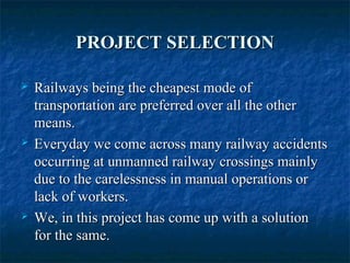
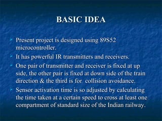
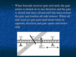
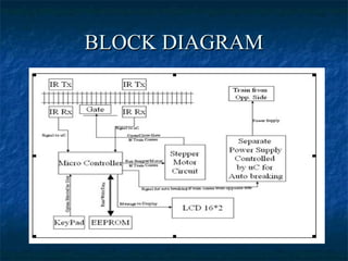


This document presents an automatic railway gate and collision avoidance system. The system uses IR sensors and a microcontroller to automatically open and close railway crossing gates based on the presence of approaching trains. It also detects oncoming trains from the opposite direction and stops train movement to prevent collisions. The system aims to reduce accidents at unmanned railway crossings by introducing automatic controls that eliminate human error.