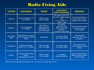
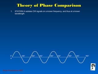
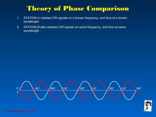
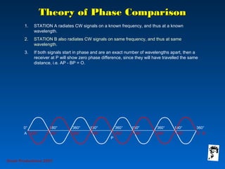
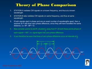
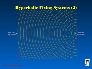
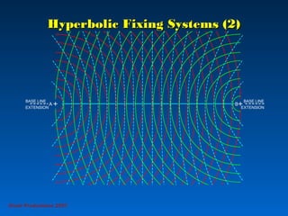
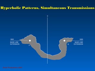
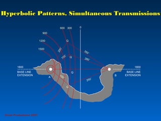
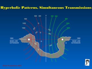
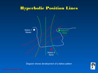
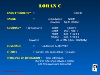
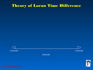
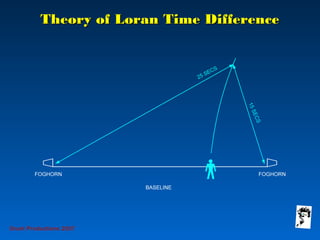
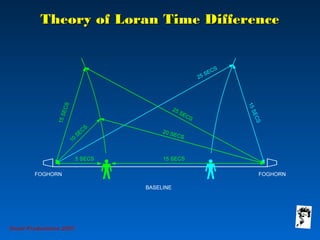
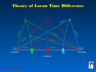
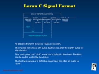
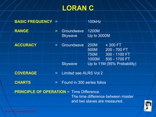
Grunt Productions 2007
Radio NavaidsRadio Navaids
A brief by LanceA brief by Lance
GrindleyGrindley
Radio Fixing AidsRadio Fixing Aids
SYSTEM BASIS/BAND RANGE
ACCURACY
(95% Probability)
REMARKS
DECCA
LORAN C
NAVSTAR
GPS
HYPERFIX
MF/DF
Phase comparison LF
(70-130kHz)
300 nm (day)
75-240 (night)
50 metres up to 100
nm from master station,
day.
6 nm at 200+ nm,
winter, night
Accuracy depends on
time of day, month,
distance from station.
Time comparison
LF (100kHz)
800-1200 nm
(ground wave)
1800-2400 nm
(sky wave-night)
50 metres
(ground wave)
(200 metres near
baseline)
10-20 nm (sky wave)
Not commonly used in
European waters.
No ambiguity
Signal time conversion
UHF (1575.42 & 1227.6
MHz)
Worldwide
21 metres (PPS)
100 metres (SPS)
Provides time
reference. P(Y) code
encryption.
Phase comparison
MF/HF (1·6 - 3.4 MHz)
380 nm (day)
135 nm (night)
10 metres (day)
50 metres (night)
Fixed and random
errors. Modern version
of Hifix.
Non-directional shore
based
radio beacons LF/MF
500 nm (day)
75 nm (night)
± 3 degrees
(ideal conditions)
Only provides bearing.
Many sources of error.
Limited range.
References: Admiralty Manual of Navigation Vol. 3., Admiralty List of Radio Signals Vol.2.
Grunt Productions 2007
Navstar GPS
Grunt Productions 2007
Navstar GPS - 24 Satellites
plus 4 Spares, 6 Orbital Planes
Grunt Productions 2007
The Navstar System
SPACE SEGMENT
28 Satellites
6 Orbits
UPLINK DATA
Satellite Ephemeris
Clock Drift
Propagation Delay
USER SEGMENT
Ships
Helicopters
etc
CONTROL SEGMENT
5 Monitor Stations
3 Antennae
1 Master Control Station
DOWNLINK DATA
Navigation
Message
Data
Grunt Productions 2007
Pseudo Range to One Satellite
Grunt Productions 2007
Correcting for Receiver Clock Error
Grunt Productions 2007
GPS Navigation Signals
L1 =
1575.42 MHz
C/A Code
at
1.023 MHz
L2 =
1227.6 MHz
P-Code
at
10.23 MHz
P-Code
at
10.23 MHz
Grunt Productions 2007
Geometry of the Satellites
a. Good (Low) Dilution of Precision b. Poor (High) Dilution of Precision
Grunt Productions 2007
GPS Accuracy
for the Fully Operational System
Absolute global time transfer to a fraction of a microsecond available continuously
Horizontal
within 8
metres
Horizontal
within 8
metres
Vertical
within 10
metres
Velocity within
0.1 knots
Grunt Productions 2007
4 Satellites provide 3 Dimensional Fix
Expected Accuracy (67%) Position 30ft
Velocity 0.1kts
Time 10 Nano Secs
Grunt Productions 2007
Differential GPS System Elements
Satcom
Link
DGPS
User
Differential
Correction
Broadcast
Data
Comms
Link
Control Centre
Differential
Reference
Station and
Broadcast
Transmitter
Radio FixingRadio Fixing
AidsAidsFREQUENCY SPECTRUM
Category Frequency Wavelength System
VLF 0-30kHz Very Long Omega
LF 30-300kHz Long Decca Loran
MF 300-3000kHz Medium MFDF Consol
HF 3-30MHz Short
VHF 30-300MHz Metric
UHF 300-3000MHz Decimetric Navstar Transit
SHF 3000-30000MHz Centimetric
E/F-Band
I-Band
EHF 30000-300000MHz Millimetric
PROPAGATION
Ground Waves
The lower the frequency, the greater the range of the ground wave signal. Ground wave
signal decreases as frequency increases due to:
A. Increased attenuation
B. A decrease in the bending of waves around the earth’s surface.
Sky Waves
These occur at frequencies between VLF and HF. Attenuation of sky waves decreases as
frequency increases, therefore increased frequency gives improved reception.
Grunt Productions 2007
Ground-Wave and Sky-Wave PathsGround-Wave and Sky-Wave Paths
UNREFLECTED
WAVE
150
27
Tx D REGION
REFLECTION
GROUND
WAVE
Rx
F LAYER
E LAYER
D REGION
50
90
190
Grunt Productions 2007
UNREFLECTED
WAVE
150
27
Tx D REGION
REFLECTION
GROUND
WAVE
Rx
F LAYER
E LAYER
D REGION
50
90
Ground-Wave and Sky-Wave PathsGround-Wave and Sky-Wave Paths
TWO HOP
190
Grunt Productions 2007
Ground-Wave and Sky-Wave PathsGround-Wave and Sky-Wave Paths
ONE HOP
UNREFLECTED
WAVE
150
27
Tx D REGION
REFLECTION
GROUND
WAVE
Rx
F LAYER
E LAYER
D REGION
50
90
190
Grunt Productions 2007
Theory of Phase ComparisonTheory of Phase Comparison
1. STATION A radiates CW signals on a known frequency, and thus at a known
wavelength.
Grunt Productions 2007
Theory of Phase ComparisonTheory of Phase Comparison
1. STATION A radiates CW signals on a known frequency, and thus at a known
wavelength.
2. STATION B also radiates CW signals on same frequency, and thus at same
wavelength.
Grunt Productions 2007
Theory of Phase ComparisonTheory of Phase Comparison
1. STATION A radiates CW signals on a known frequency, and thus at a known
wavelength.
2. STATION B also radiates CW signals on same frequency, and thus at same
wavelength.
3. If both signals start in phase and are an exact number of wavelengths apart, then a
receiver at P will show zero phase difference, since they will have travelled the same
distance, i.e. AP - BP = O.
4. Now consider points Q and R, situated λ away from P. At both these points phase of
each signal = 180°, i.e. signal again has zero phase difference.
5. It can therefore be seen that lines of zero phase difference occur at intervals of λ._
2
_
2
Grunt Productions 2007
B
Hyperbolic Fixing Systems (2)Hyperbolic Fixing Systems (2)
BASE LINE
EXTENSION
BASE LINE
EXTENSION
A
Grunt Productions 2007
Hyperbolic Fixing Systems (2)Hyperbolic Fixing Systems (2)
BASE LINE
EXTENSION
BASE LINE
EXTENSION
A B
Grunt Productions 2007
Hyperbolic Fixing Systems (2)Hyperbolic Fixing Systems (2)
BASE LINE
EXTENSION
BASE LINE
EXTENSION
BA
Grunt Productions 2007
Hyperbolic Fixing Systems (2)Hyperbolic Fixing Systems (2)
BASE LINE
EXTENSION
BASE LINE
EXTENSION
BA
Grunt Productions 2007
Hyperbolic Patterns, Simultaneous TransmissionsHyperbolic Patterns, Simultaneous Transmissions
0
A
B
1800
BASE LINE
EXTENSION
1800
BASE LINE
EXTENSION
Grunt Productions 2007
250´
280´
350´
150´
250´
Q
Q
Hyperbolic Patterns, Simultaneous TransmissionsHyperbolic Patterns, Simultaneous Transmissions
0
A
B
1800
BASE LINE
EXTENSION
1800
BASE LINE
EXTENSION
300600
900
1200
1500
150´
Q
Q
Grunt Productions 2007
250´
280´
350´
150´
250´
Q
Q
Hyperbolic Patterns, Simultaneous TransmissionsHyperbolic Patterns, Simultaneous Transmissions
0
A
B
1800
BASE LINE
EXTENSION
1800
BASE LINE
EXTENSION
300600
900
1200
1500
300 600
900
1200
1500
150´
Q
Q
Grunt Productions 2007
Hyperbolic Position LinesHyperbolic Position Lines
Diagram shows development of a lattice pattern
Station 3
Slave
Station 1
Master
Station 2
Slave
Grunt Productions 2007
LORAN CLORAN C
BASIC FREQUENCY = 100kHz
RANGE = Groundwave 1200M
Skywave Up to 3000M
ACCURACY = Groundwave 200M < 300 FT
500M 200 - 700 FT
750M 300 - 1100 FT
1000M 500 - 1700 FT
Skywave Up to 11M (95% Probability)
COVERAGE = Limited see ALRS Vol 2
CHARTS =Found in 300 series folios (Not used)
PRINCIPLE OF OPERATION = Time Difference.
The time difference between master
and two slaves are measured.
Grunt Productions 2007
Theory of Loran Time DifferenceTheory of Loran Time Difference
Grunt Productions 2007
Theory of Loran Time DifferenceTheory of Loran Time Difference
Grunt Productions 2007
Theory of Loran Time DifferenceTheory of Loran Time Difference
Grunt Productions 2007
Theory of Loran Time DifferenceTheory of Loran Time Difference
Grunt Productions 2007
Hyperbolic Fixing StationsHyperbolic Fixing Stations
Grunt Productions 2007
Hyperbolic Fixing StationsHyperbolic Fixing Stations
1. Simultaneous transmissions - ambiguity exists.
2. Master triggers Slave - Slave delays 500µs ambiguity
resolved.
Grunt Productions 2007
Hyperbolic Fixing StationsHyperbolic Fixing Stations
1. Simultaneous transmissions - ambiguity exists.
Grunt Productions 2007
Layout of a StationLayout of a Station
The master station transmits first and then secondaries follow in
sequence after “secondary coding delay”.
Notes: Coding delay ensures:
1. Slaves cannot be received out of alphabetical sequence.
2. Correct identification of slave by time difference “slot”.
Grunt Productions 2007
Loran C Signal FormatLoran C Signal Format
All stations transmit 8 pulses 1000µ secs apart.
The master transmits a 9th pulse 2000µ secs after the eighth pulse for
identification.
This ninth pulse can “blink” to warn of a defect in the chain. The blink
can be coded to identify the defect.
The first two pulses of a defective secondary can also be made to
“blink”.
Grunt Productions 2007
LORAN C
BASIC FREQUENCY = 100kHz
RANGE = Groundwave 1200M
Skywave Up to 3000M
ACCURACY = Groundwave 200M < 300 FT
500M 200 - 700 FT
750M 300 - 1100 FT
1000M 500 - 1700 FT
Skywave Up to 11M (95% Probability)
COVERAGE = Limited see ALRS Vol 2
CHARTS = Found in 300 series folios
PRINCIPLE OF OPERATION = Time Difference.
The time difference between master
and two slaves are measured.

Radio navaids

  • 1.
    Grunt Productions 2007 RadioNavaidsRadio Navaids A brief by LanceA brief by Lance GrindleyGrindley
  • 2.
    Radio Fixing AidsRadioFixing Aids SYSTEM BASIS/BAND RANGE ACCURACY (95% Probability) REMARKS DECCA LORAN C NAVSTAR GPS HYPERFIX MF/DF Phase comparison LF (70-130kHz) 300 nm (day) 75-240 (night) 50 metres up to 100 nm from master station, day. 6 nm at 200+ nm, winter, night Accuracy depends on time of day, month, distance from station. Time comparison LF (100kHz) 800-1200 nm (ground wave) 1800-2400 nm (sky wave-night) 50 metres (ground wave) (200 metres near baseline) 10-20 nm (sky wave) Not commonly used in European waters. No ambiguity Signal time conversion UHF (1575.42 & 1227.6 MHz) Worldwide 21 metres (PPS) 100 metres (SPS) Provides time reference. P(Y) code encryption. Phase comparison MF/HF (1·6 - 3.4 MHz) 380 nm (day) 135 nm (night) 10 metres (day) 50 metres (night) Fixed and random errors. Modern version of Hifix. Non-directional shore based radio beacons LF/MF 500 nm (day) 75 nm (night) ± 3 degrees (ideal conditions) Only provides bearing. Many sources of error. Limited range. References: Admiralty Manual of Navigation Vol. 3., Admiralty List of Radio Signals Vol.2.
  • 3.
  • 4.
    Grunt Productions 2007 NavstarGPS - 24 Satellites plus 4 Spares, 6 Orbital Planes
  • 5.
    Grunt Productions 2007 TheNavstar System SPACE SEGMENT 28 Satellites 6 Orbits UPLINK DATA Satellite Ephemeris Clock Drift Propagation Delay USER SEGMENT Ships Helicopters etc CONTROL SEGMENT 5 Monitor Stations 3 Antennae 1 Master Control Station DOWNLINK DATA Navigation Message Data
  • 6.
    Grunt Productions 2007 PseudoRange to One Satellite
  • 7.
    Grunt Productions 2007 Correctingfor Receiver Clock Error
  • 8.
    Grunt Productions 2007 GPSNavigation Signals L1 = 1575.42 MHz C/A Code at 1.023 MHz L2 = 1227.6 MHz P-Code at 10.23 MHz P-Code at 10.23 MHz
  • 9.
    Grunt Productions 2007 Geometryof the Satellites a. Good (Low) Dilution of Precision b. Poor (High) Dilution of Precision
  • 10.
    Grunt Productions 2007 GPSAccuracy for the Fully Operational System Absolute global time transfer to a fraction of a microsecond available continuously Horizontal within 8 metres Horizontal within 8 metres Vertical within 10 metres Velocity within 0.1 knots
  • 11.
    Grunt Productions 2007 4Satellites provide 3 Dimensional Fix Expected Accuracy (67%) Position 30ft Velocity 0.1kts Time 10 Nano Secs
  • 12.
    Grunt Productions 2007 DifferentialGPS System Elements Satcom Link DGPS User Differential Correction Broadcast Data Comms Link Control Centre Differential Reference Station and Broadcast Transmitter
  • 13.
    Radio FixingRadio Fixing AidsAidsFREQUENCYSPECTRUM Category Frequency Wavelength System VLF 0-30kHz Very Long Omega LF 30-300kHz Long Decca Loran MF 300-3000kHz Medium MFDF Consol HF 3-30MHz Short VHF 30-300MHz Metric UHF 300-3000MHz Decimetric Navstar Transit SHF 3000-30000MHz Centimetric E/F-Band I-Band EHF 30000-300000MHz Millimetric PROPAGATION Ground Waves The lower the frequency, the greater the range of the ground wave signal. Ground wave signal decreases as frequency increases due to: A. Increased attenuation B. A decrease in the bending of waves around the earth’s surface. Sky Waves These occur at frequencies between VLF and HF. Attenuation of sky waves decreases as frequency increases, therefore increased frequency gives improved reception. Grunt Productions 2007
  • 14.
    Ground-Wave and Sky-WavePathsGround-Wave and Sky-Wave Paths UNREFLECTED WAVE 150 27 Tx D REGION REFLECTION GROUND WAVE Rx F LAYER E LAYER D REGION 50 90 190 Grunt Productions 2007
  • 15.
    UNREFLECTED WAVE 150 27 Tx D REGION REFLECTION GROUND WAVE Rx FLAYER E LAYER D REGION 50 90 Ground-Wave and Sky-Wave PathsGround-Wave and Sky-Wave Paths TWO HOP 190 Grunt Productions 2007
  • 16.
    Ground-Wave and Sky-WavePathsGround-Wave and Sky-Wave Paths ONE HOP UNREFLECTED WAVE 150 27 Tx D REGION REFLECTION GROUND WAVE Rx F LAYER E LAYER D REGION 50 90 190 Grunt Productions 2007
  • 17.
    Theory of PhaseComparisonTheory of Phase Comparison 1. STATION A radiates CW signals on a known frequency, and thus at a known wavelength. Grunt Productions 2007
  • 18.
    Theory of PhaseComparisonTheory of Phase Comparison 1. STATION A radiates CW signals on a known frequency, and thus at a known wavelength. 2. STATION B also radiates CW signals on same frequency, and thus at same wavelength. Grunt Productions 2007
  • 19.
    Theory of PhaseComparisonTheory of Phase Comparison 1. STATION A radiates CW signals on a known frequency, and thus at a known wavelength. 2. STATION B also radiates CW signals on same frequency, and thus at same wavelength. 3. If both signals start in phase and are an exact number of wavelengths apart, then a receiver at P will show zero phase difference, since they will have travelled the same distance, i.e. AP - BP = O. Grunt Productions 2007
  • 20.
    Theory of PhaseComparisonTheory of Phase Comparison 1. STATION A radiates CW signals on a known frequency, and thus at a known wavelength. 2. STATION B also radiates CW signals on same frequency, and thus at same wavelength. 3. If both signals start in phase and are an exact number of wavelengths apart, then a receiver at P will show zero phase difference, since they will have travelled the same distance, i.e. AP - BP = O. 4. Now consider points Q and R, situated λ away from P. At both these points phase of each signal = 180°, i.e. signal again has zero phase difference. 5. It can therefore be seen that lines of zero phase difference occur at intervals of λ._ 2 _ 2 Grunt Productions 2007
  • 21.
    B Hyperbolic Fixing Systems(2)Hyperbolic Fixing Systems (2) BASE LINE EXTENSION BASE LINE EXTENSION A Grunt Productions 2007
  • 22.
    Hyperbolic Fixing Systems(2)Hyperbolic Fixing Systems (2) BASE LINE EXTENSION BASE LINE EXTENSION A B Grunt Productions 2007
  • 23.
    Hyperbolic Fixing Systems(2)Hyperbolic Fixing Systems (2) BASE LINE EXTENSION BASE LINE EXTENSION BA Grunt Productions 2007
  • 24.
    Hyperbolic Fixing Systems(2)Hyperbolic Fixing Systems (2) BASE LINE EXTENSION BASE LINE EXTENSION BA Grunt Productions 2007
  • 25.
    Hyperbolic Patterns, SimultaneousTransmissionsHyperbolic Patterns, Simultaneous Transmissions 0 A B 1800 BASE LINE EXTENSION 1800 BASE LINE EXTENSION Grunt Productions 2007
  • 26.
    250´ 280´ 350´ 150´ 250´ Q Q Hyperbolic Patterns, SimultaneousTransmissionsHyperbolic Patterns, Simultaneous Transmissions 0 A B 1800 BASE LINE EXTENSION 1800 BASE LINE EXTENSION 300600 900 1200 1500 150´ Q Q Grunt Productions 2007
  • 27.
    250´ 280´ 350´ 150´ 250´ Q Q Hyperbolic Patterns, SimultaneousTransmissionsHyperbolic Patterns, Simultaneous Transmissions 0 A B 1800 BASE LINE EXTENSION 1800 BASE LINE EXTENSION 300600 900 1200 1500 300 600 900 1200 1500 150´ Q Q Grunt Productions 2007
  • 28.
    Hyperbolic Position LinesHyperbolicPosition Lines Diagram shows development of a lattice pattern Station 3 Slave Station 1 Master Station 2 Slave Grunt Productions 2007
  • 29.
    LORAN CLORAN C BASICFREQUENCY = 100kHz RANGE = Groundwave 1200M Skywave Up to 3000M ACCURACY = Groundwave 200M < 300 FT 500M 200 - 700 FT 750M 300 - 1100 FT 1000M 500 - 1700 FT Skywave Up to 11M (95% Probability) COVERAGE = Limited see ALRS Vol 2 CHARTS =Found in 300 series folios (Not used) PRINCIPLE OF OPERATION = Time Difference. The time difference between master and two slaves are measured. Grunt Productions 2007
  • 30.
    Theory of LoranTime DifferenceTheory of Loran Time Difference Grunt Productions 2007
  • 31.
    Theory of LoranTime DifferenceTheory of Loran Time Difference Grunt Productions 2007
  • 32.
    Theory of LoranTime DifferenceTheory of Loran Time Difference Grunt Productions 2007
  • 33.
    Theory of LoranTime DifferenceTheory of Loran Time Difference Grunt Productions 2007
  • 34.
    Hyperbolic Fixing StationsHyperbolicFixing Stations Grunt Productions 2007
  • 35.
    Hyperbolic Fixing StationsHyperbolicFixing Stations 1. Simultaneous transmissions - ambiguity exists. 2. Master triggers Slave - Slave delays 500µs ambiguity resolved. Grunt Productions 2007
  • 36.
    Hyperbolic Fixing StationsHyperbolicFixing Stations 1. Simultaneous transmissions - ambiguity exists. Grunt Productions 2007
  • 37.
    Layout of aStationLayout of a Station The master station transmits first and then secondaries follow in sequence after “secondary coding delay”. Notes: Coding delay ensures: 1. Slaves cannot be received out of alphabetical sequence. 2. Correct identification of slave by time difference “slot”. Grunt Productions 2007
  • 38.
    Loran C SignalFormatLoran C Signal Format All stations transmit 8 pulses 1000µ secs apart. The master transmits a 9th pulse 2000µ secs after the eighth pulse for identification. This ninth pulse can “blink” to warn of a defect in the chain. The blink can be coded to identify the defect. The first two pulses of a defective secondary can also be made to “blink”. Grunt Productions 2007
  • 39.
    Grunt Productions 2007 LORANC BASIC FREQUENCY = 100kHz RANGE = Groundwave 1200M Skywave Up to 3000M ACCURACY = Groundwave 200M < 300 FT 500M 200 - 700 FT 750M 300 - 1100 FT 1000M 500 - 1700 FT Skywave Up to 11M (95% Probability) COVERAGE = Limited see ALRS Vol 2 CHARTS = Found in 300 series folios PRINCIPLE OF OPERATION = Time Difference. The time difference between master and two slaves are measured.