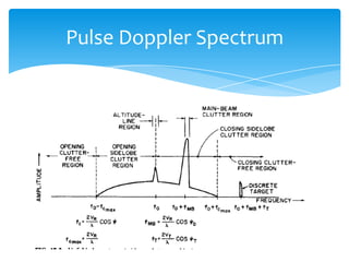
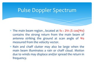
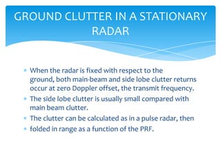
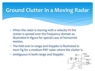
Pulse Doppler Spectrum
By
Tariq Kanher
Pulse Doppler Spectrum
Pulse Doppler Clutter
Ground Clutter in Stationary Radar
Ground Clutter in Moving Radar
Sidelobe Clutter
Main Beam Clutter
Single Target Tracking
Multiple Target Tracking
Agenda
Pulse Doppler Spectrum
previous figure show the unfolded spectrum in case
of horizental motion of radar, with a velocity VR .
The clutter free region in define as that portion of the
spectrum in which no ground clutter can exist.
The side lobe clutter region, 4VR /λ in width, contains
ground clutter power from the side lobes of the
antenna, although the clutter power may be below
the noise level in part of the region.
Pulse Doppler Spectrum
Altitude line clutter, which is due to ground clutter at
near normal incidence directly below the radar
platform, is at zero Doppler if there is no vertical
component of platform velocity.
A discrete target return in the main beam is shown at
fT = f0 + 2VR /λ cos (Ψo) + 2VT /λ cos (ΨT) ,where the
target velocity is VT with an angle between the target
velocity vector and radar target line of sight.
Pulse Doppler Spectrum
The main beam region , located at f0 + 2VR /λ cos(Ψo)
contains the strong return from the main beam of
antenna striking the ground at scan angle of Ψo
measured from the velocity vector.
Rain and chaff clutter may also be large when the
main beam illuminates a rain or chaff cloud. Motion
due to winds may displace and/or spread the return in
frequency.
Pulse Doppler Spectrum
Clutter returns from various scatters have a strong
influence on the design of a pulse Doppler radar as
well as an effect on the probability of detection of
point targets.
PULSE DOPPLER CLUTTER
When the radar is fixed with respect to the
ground, both main-beam and side lobe clutter returns
occur at zero Doppler offset, the transmit frequency.
The side lobe clutter is usually small compared with
main beam clutter.
The clutter can be calculated as in a pulse radar, then
folded in range as a function of the PRF.
GROUND CLUTTER IN A STATIONARY
RADAR
When the radar is moving with a velocity VR the
clutter is spread over the frequency domain as
illustrated in figure for special case of horizontal
motion.
The fold over in range and Doppler is illustrated in
next Fig for a medium-PRF radar where the clutter is
ambiguous in both range and Doppler.
Ground Clutter in a Moving Radar
The radar platform is moving to the right at 1000km
with a drive angle of 10 degree.
The narrow annuli define the ground area that
contributes to clutter in the selected range gate.
The five narrow hyperbolic bands define the area that
contributes to clutter.
Ground Clutter in a Moving Radar
The entire clutter spectrum can be calculated for each
range gate by Equation next slide, if the antenna
pattern is known in the lower hemisphere.
In preliminary system design, the exact gain function
may not be known, so that one useful approximation
is that the side lobe radiation is isotropic with a
constant gain of GSL .
Side lobe Clutter
The main-beam clutter-to-noise power can be
approximated from equation
The summation limits are the lower and upper edges
of the smaller of the transmit and receive beams.
Main-Beam Clutter
Main-Beam Clutter
Tracking can be identical to a congenital pulse radar
using mono pulses, sequential lobbing or conical scan.
Mono pulse is more difficult to mechanize because of
the problem of phase and amplitude matching of the
multiple receiver channels.
Single-Target Tracking
Multiple target tracking can be accomplished in
several ways.
One, track while scan , is to use normal search mode
with FM or multiple PRF ranging and store the
range, angle and Doppler of the reported detection in
the computer.
Multiple-Target Tracking
A second method of multiple-target tracking, pause-
while-scan, particularly applicable to electronic scan
antennas, is to scan in a normal search pattern pause
on each search detection, and enter a single-target
track mode for a brief period.
PULSE DOPPLER RADAR
William H. Long
David H. Mooney
William A. Skillman
Westinghouse Electric Corporation
Reference
Pulse Doppler Effect

Pulse Doppler Effect

  • 1.
  • 2.
    Pulse Doppler Spectrum PulseDoppler Clutter Ground Clutter in Stationary Radar Ground Clutter in Moving Radar Sidelobe Clutter Main Beam Clutter Single Target Tracking Multiple Target Tracking Agenda
  • 3.
  • 4.
  • 5.
  • 6.
  • 7.
    previous figure showthe unfolded spectrum in case of horizental motion of radar, with a velocity VR . The clutter free region in define as that portion of the spectrum in which no ground clutter can exist. The side lobe clutter region, 4VR /λ in width, contains ground clutter power from the side lobes of the antenna, although the clutter power may be below the noise level in part of the region. Pulse Doppler Spectrum
  • 8.
    Altitude line clutter,which is due to ground clutter at near normal incidence directly below the radar platform, is at zero Doppler if there is no vertical component of platform velocity. A discrete target return in the main beam is shown at fT = f0 + 2VR /λ cos (Ψo) + 2VT /λ cos (ΨT) ,where the target velocity is VT with an angle between the target velocity vector and radar target line of sight. Pulse Doppler Spectrum
  • 9.
    The main beamregion , located at f0 + 2VR /λ cos(Ψo) contains the strong return from the main beam of antenna striking the ground at scan angle of Ψo measured from the velocity vector. Rain and chaff clutter may also be large when the main beam illuminates a rain or chaff cloud. Motion due to winds may displace and/or spread the return in frequency. Pulse Doppler Spectrum
  • 10.
    Clutter returns fromvarious scatters have a strong influence on the design of a pulse Doppler radar as well as an effect on the probability of detection of point targets. PULSE DOPPLER CLUTTER
  • 11.
    When the radaris fixed with respect to the ground, both main-beam and side lobe clutter returns occur at zero Doppler offset, the transmit frequency. The side lobe clutter is usually small compared with main beam clutter. The clutter can be calculated as in a pulse radar, then folded in range as a function of the PRF. GROUND CLUTTER IN A STATIONARY RADAR
  • 12.
    When the radaris moving with a velocity VR the clutter is spread over the frequency domain as illustrated in figure for special case of horizontal motion. The fold over in range and Doppler is illustrated in next Fig for a medium-PRF radar where the clutter is ambiguous in both range and Doppler. Ground Clutter in a Moving Radar
  • 14.
    The radar platformis moving to the right at 1000km with a drive angle of 10 degree. The narrow annuli define the ground area that contributes to clutter in the selected range gate. The five narrow hyperbolic bands define the area that contributes to clutter. Ground Clutter in a Moving Radar
  • 15.
    The entire clutterspectrum can be calculated for each range gate by Equation next slide, if the antenna pattern is known in the lower hemisphere. In preliminary system design, the exact gain function may not be known, so that one useful approximation is that the side lobe radiation is isotropic with a constant gain of GSL . Side lobe Clutter
  • 17.
    The main-beam clutter-to-noisepower can be approximated from equation The summation limits are the lower and upper edges of the smaller of the transmit and receive beams. Main-Beam Clutter
  • 18.
  • 19.
    Tracking can beidentical to a congenital pulse radar using mono pulses, sequential lobbing or conical scan. Mono pulse is more difficult to mechanize because of the problem of phase and amplitude matching of the multiple receiver channels. Single-Target Tracking
  • 20.
    Multiple target trackingcan be accomplished in several ways. One, track while scan , is to use normal search mode with FM or multiple PRF ranging and store the range, angle and Doppler of the reported detection in the computer. Multiple-Target Tracking
  • 21.
    A second methodof multiple-target tracking, pause- while-scan, particularly applicable to electronic scan antennas, is to scan in a normal search pattern pause on each search detection, and enter a single-target track mode for a brief period.
  • 22.
    PULSE DOPPLER RADAR WilliamH. Long David H. Mooney William A. Skillman Westinghouse Electric Corporation Reference