
Downloaded 234 times
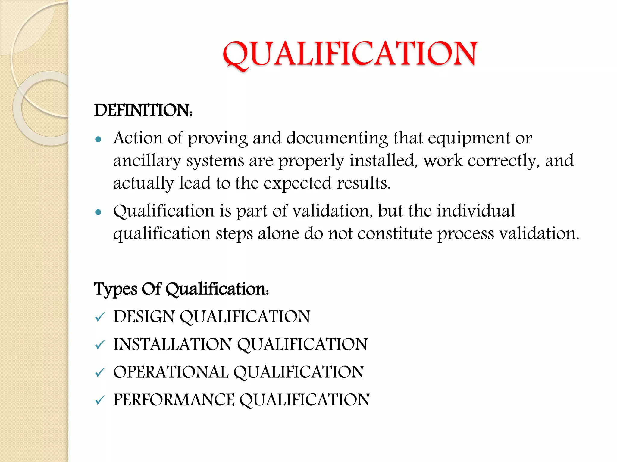


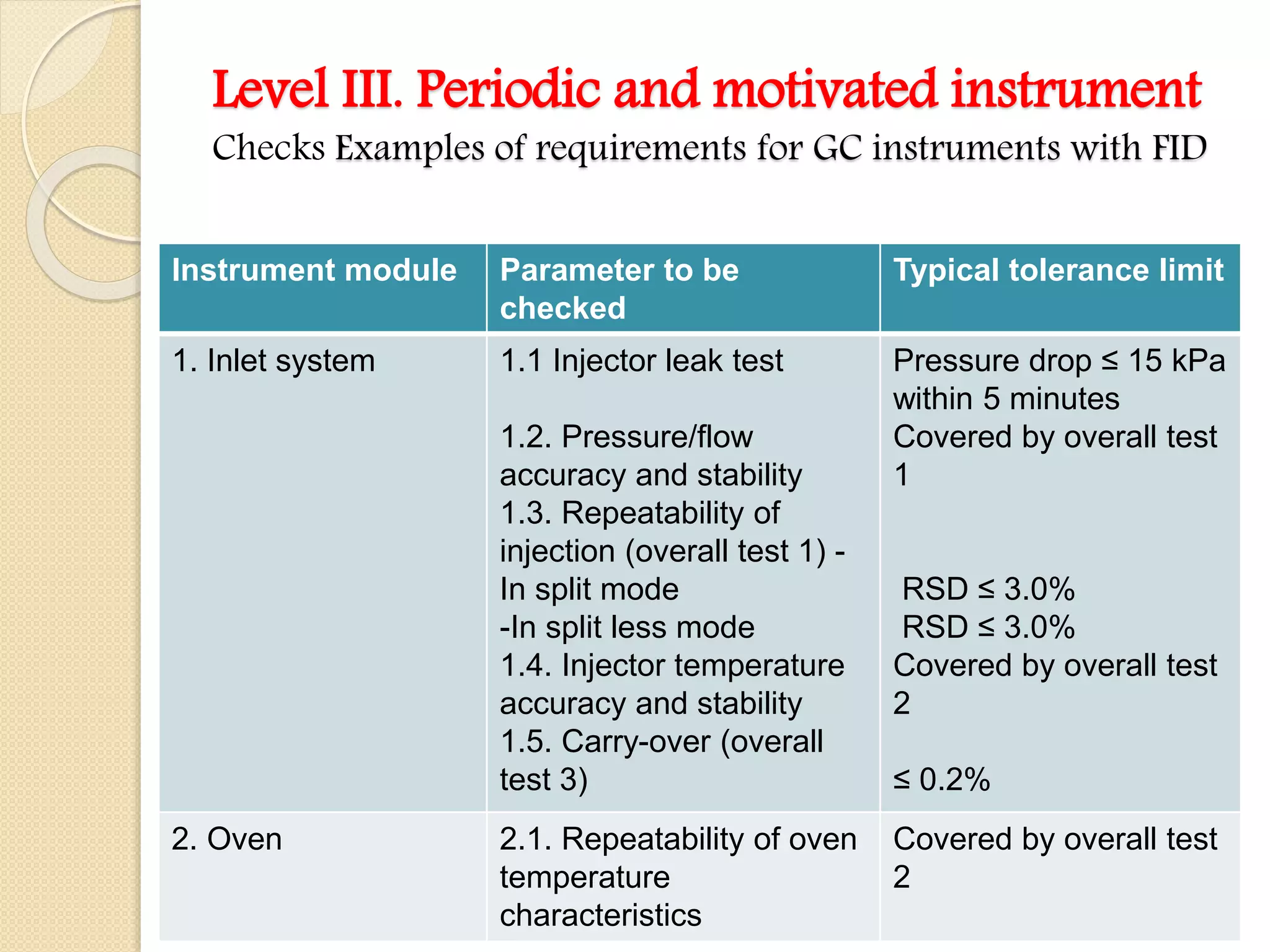
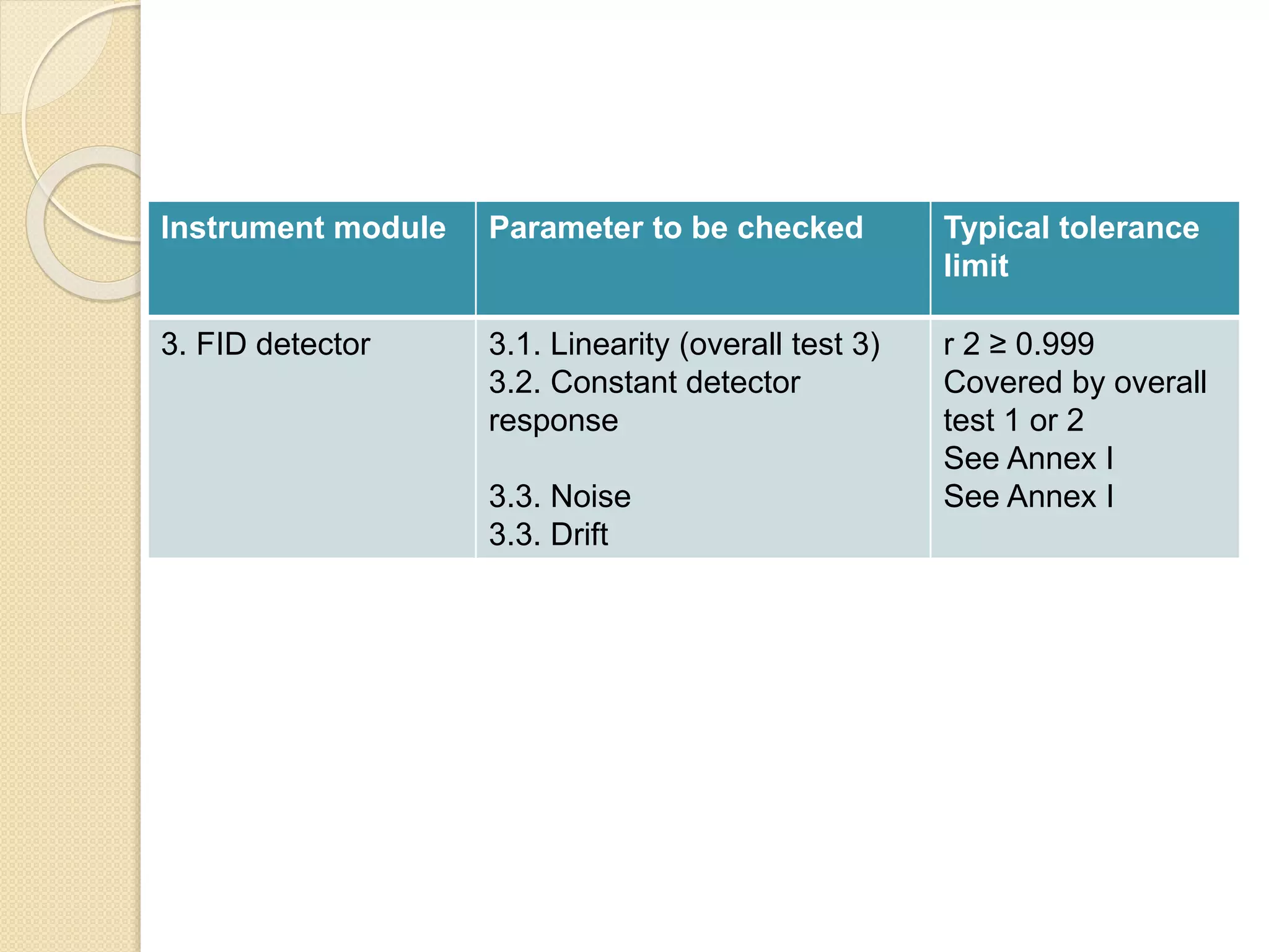


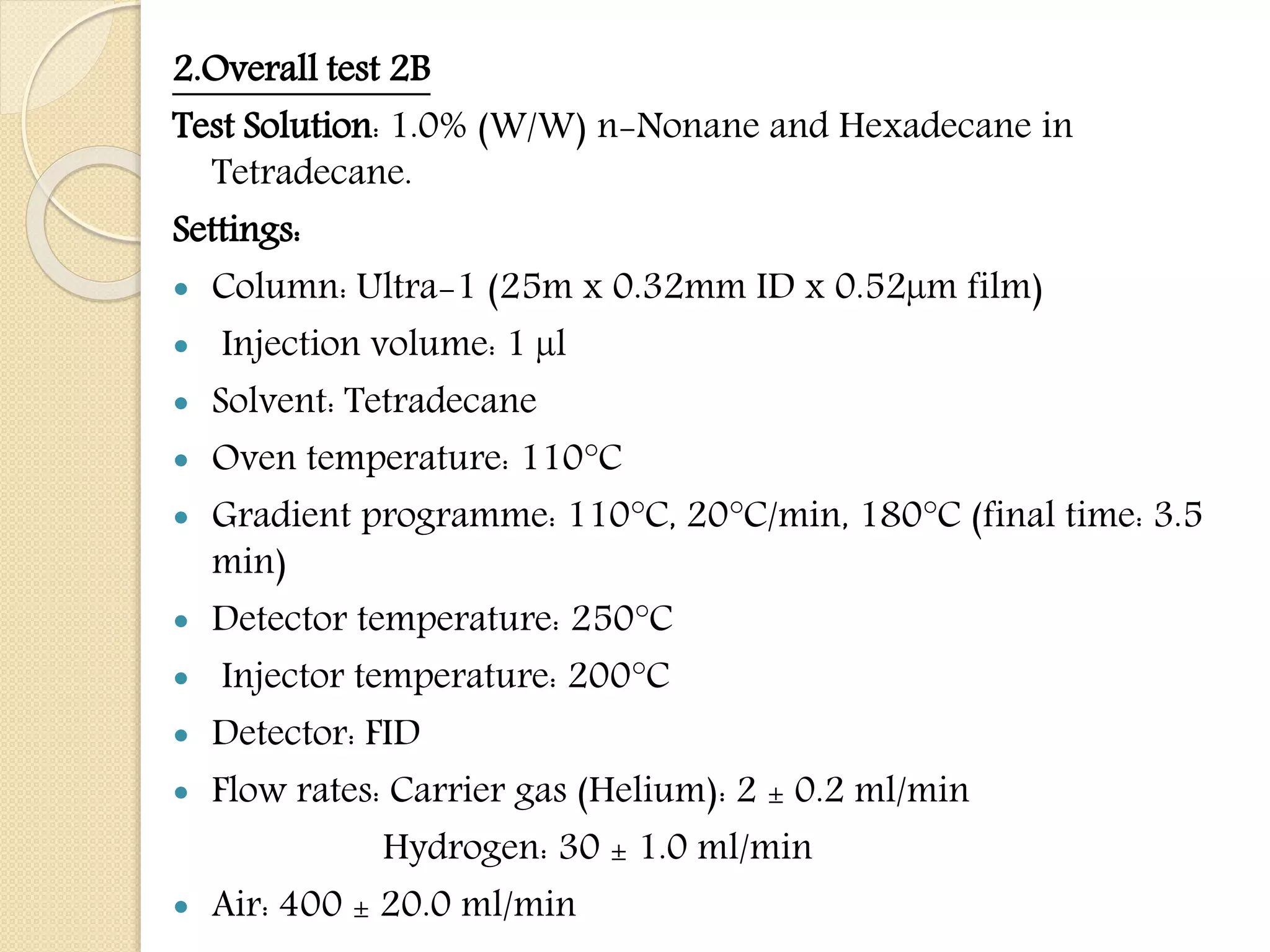


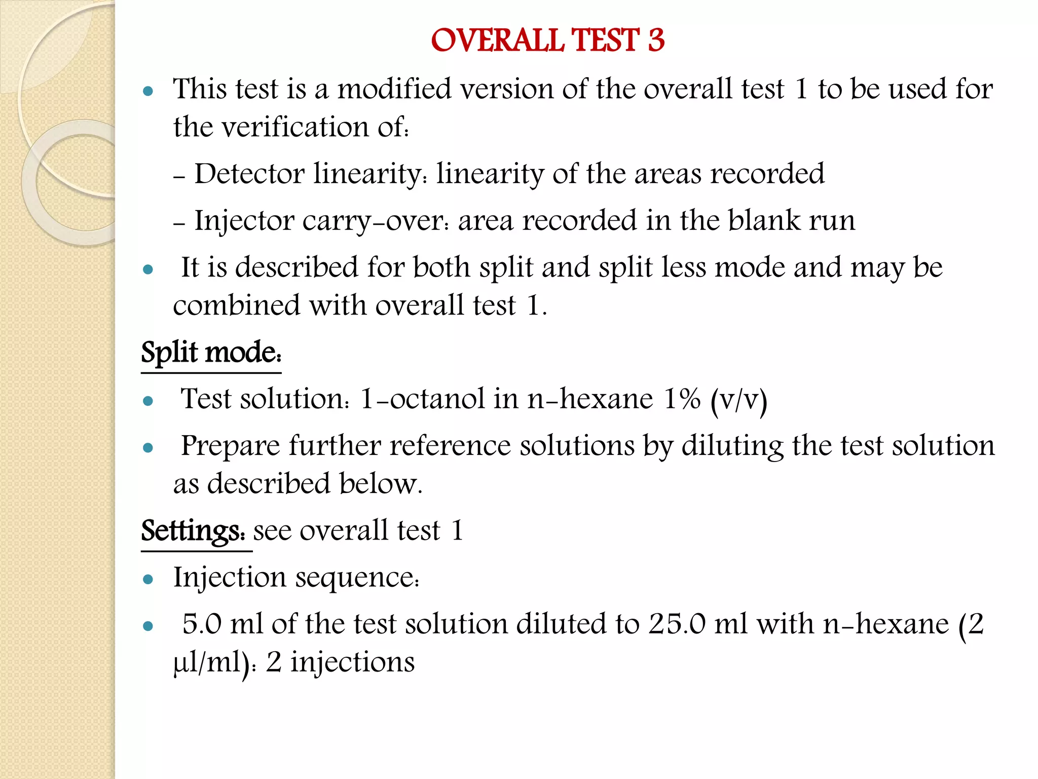


The document discusses the qualification of gas chromatography equipment. It defines qualification and describes the types including design, installation, operational, and performance qualification. It provides details on installation qualification, operational qualification, and performance qualification. The document then discusses qualification of GC equipment specifically, outlining the objectives and levels of qualification. It provides examples of tests and parameters to check at each level, including for the inlet system, oven, and detector, with typical tolerance limits. The tests include overall tests to check multiple parameters at once.


