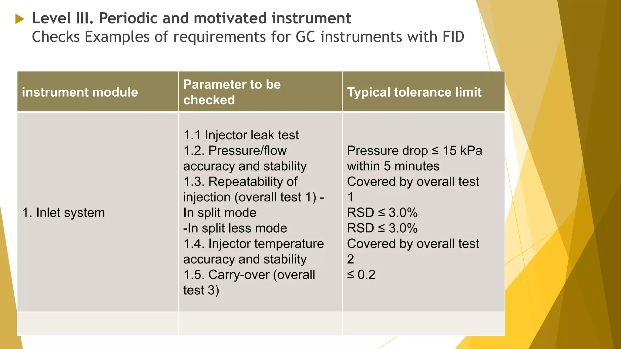
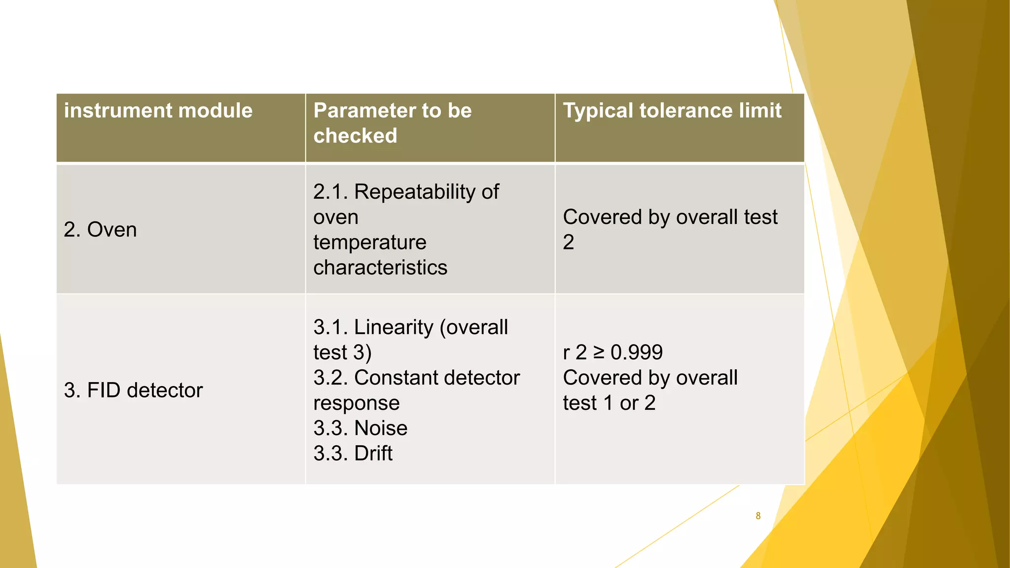
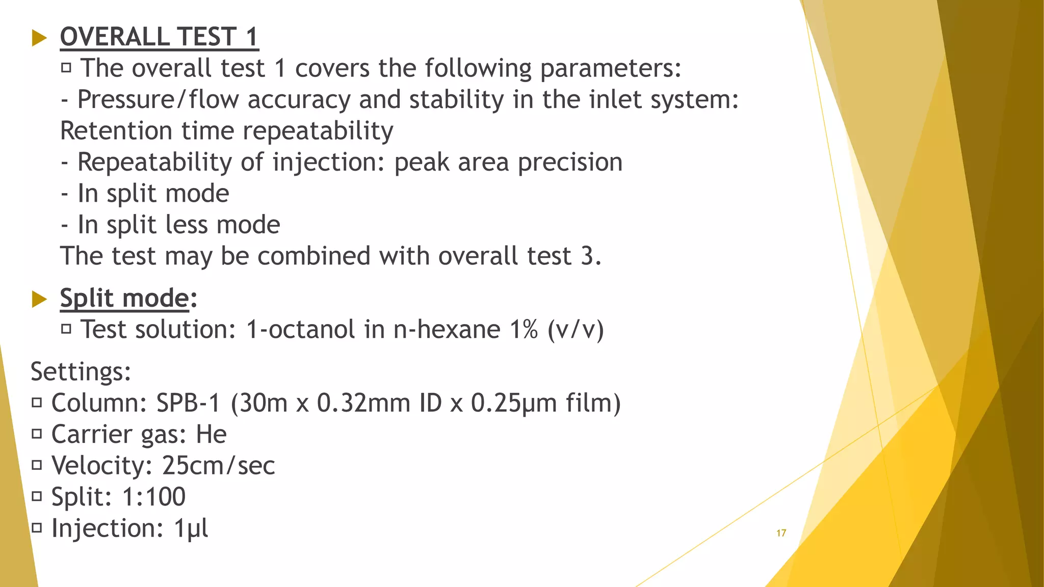
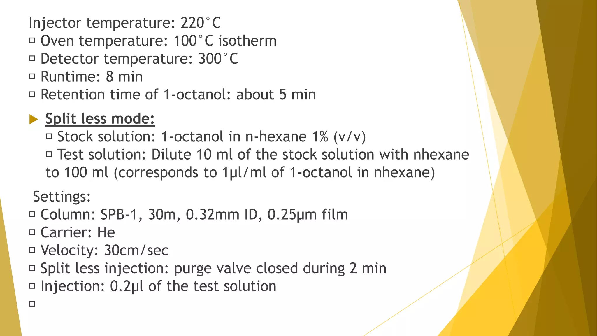
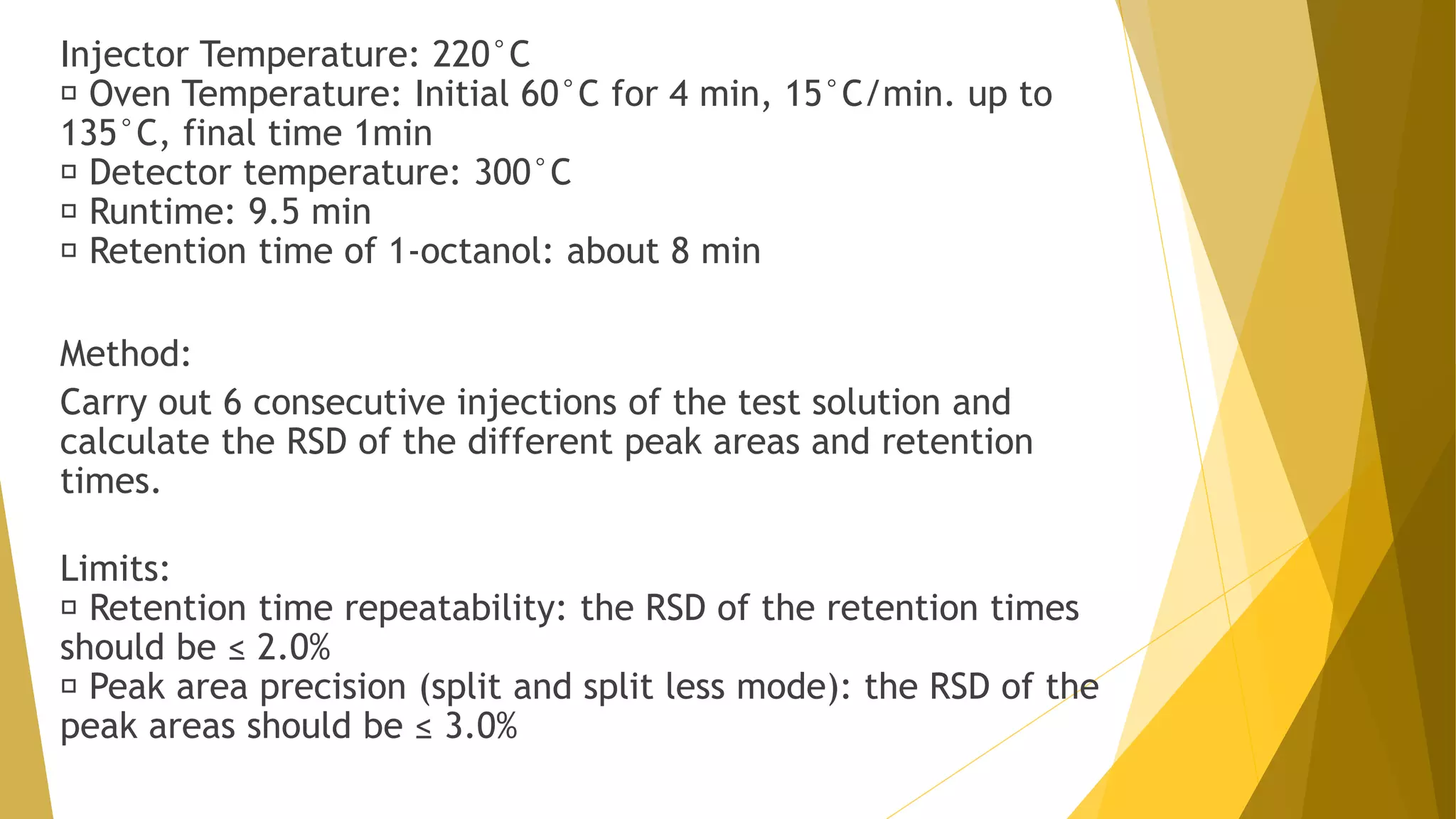
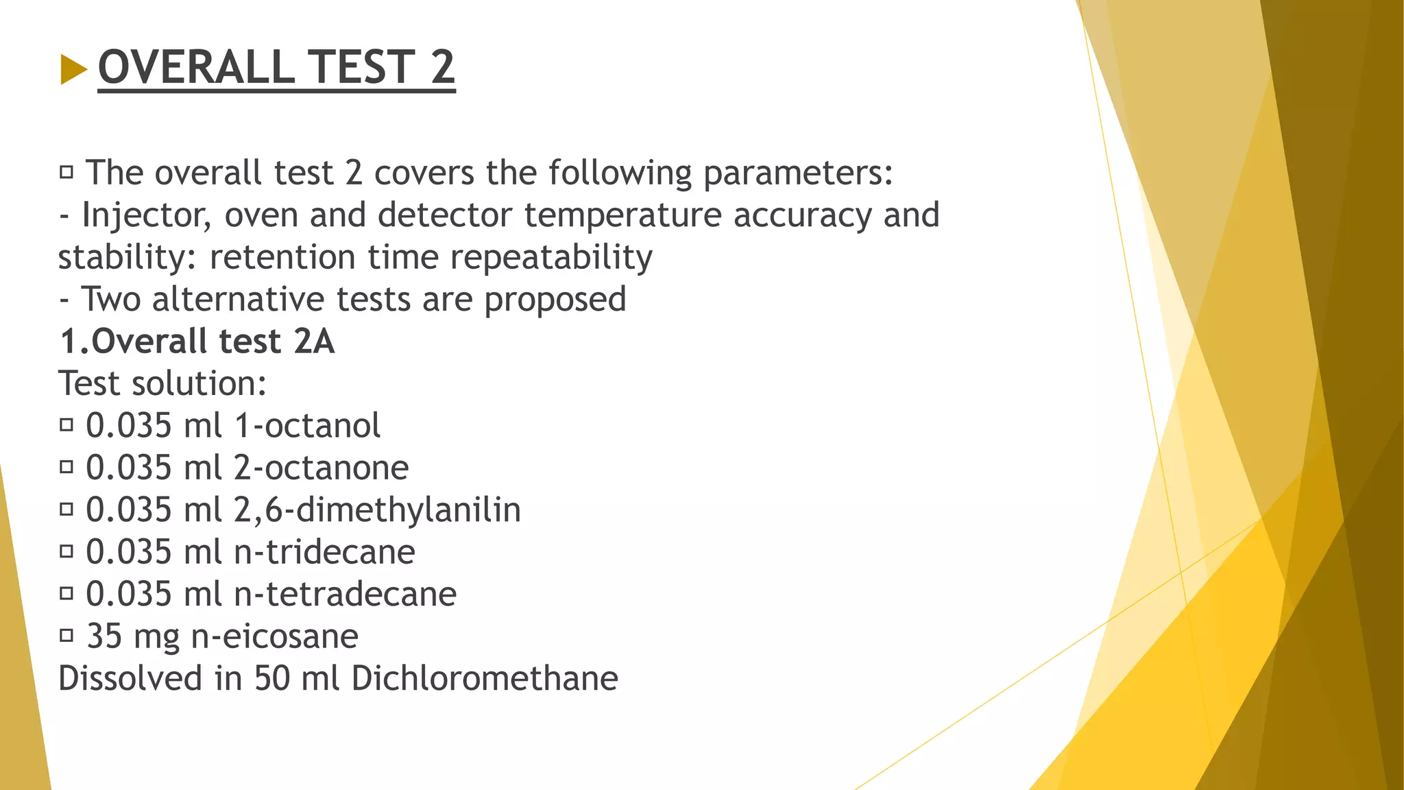
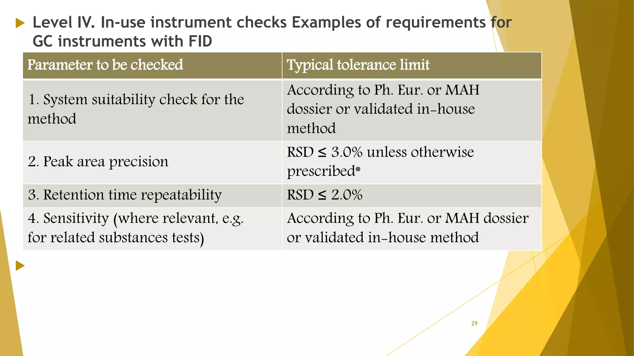
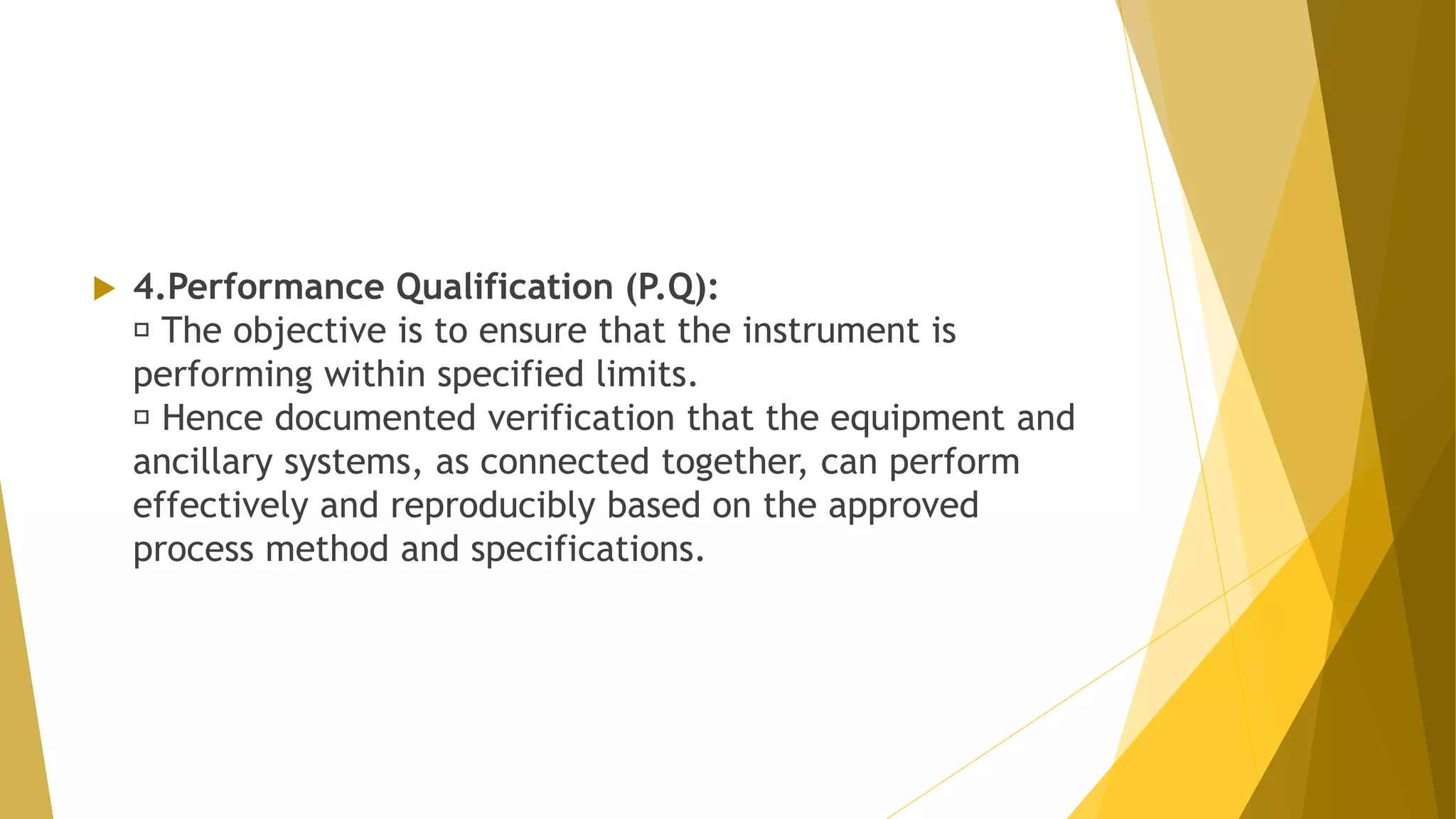
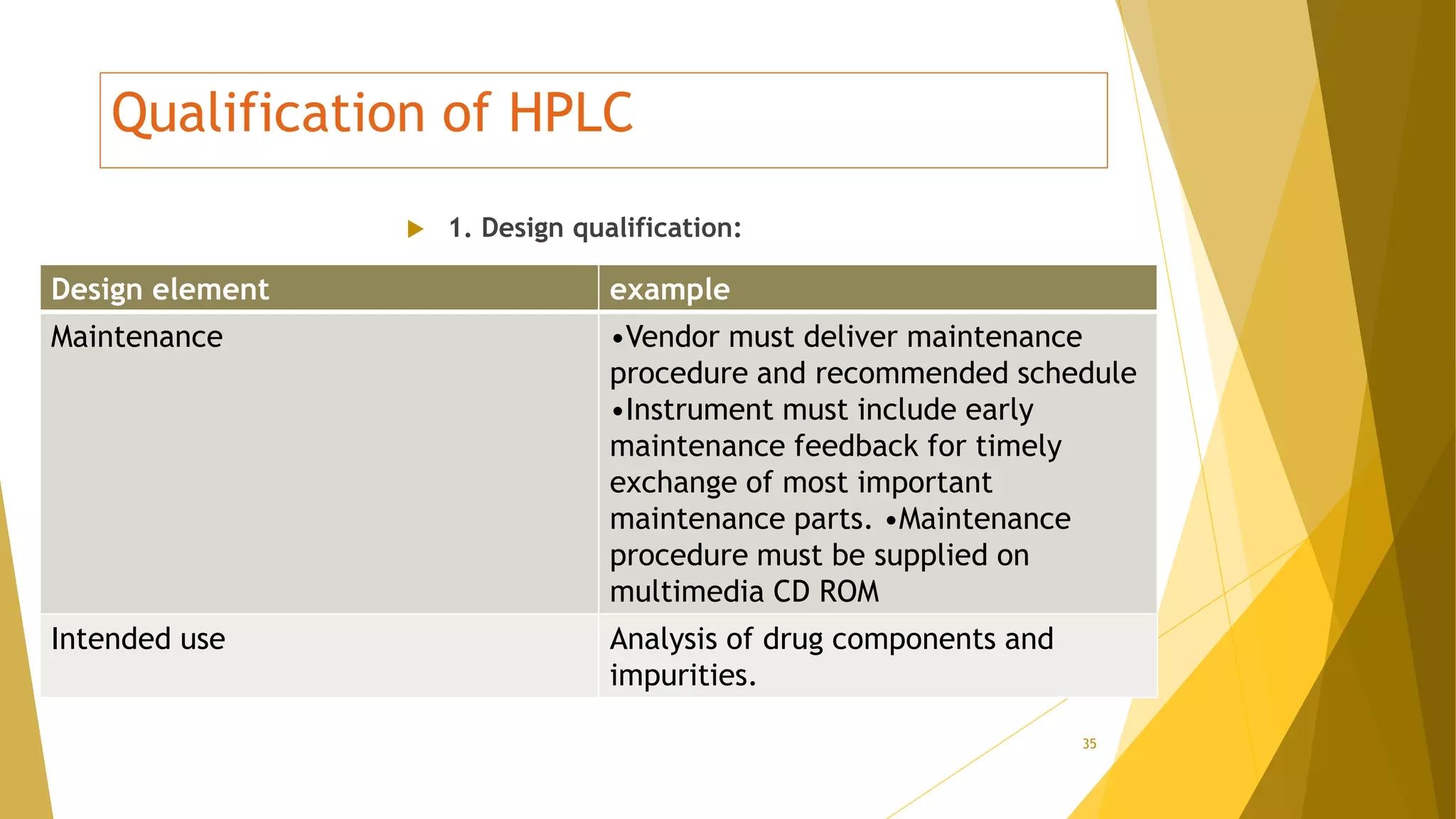
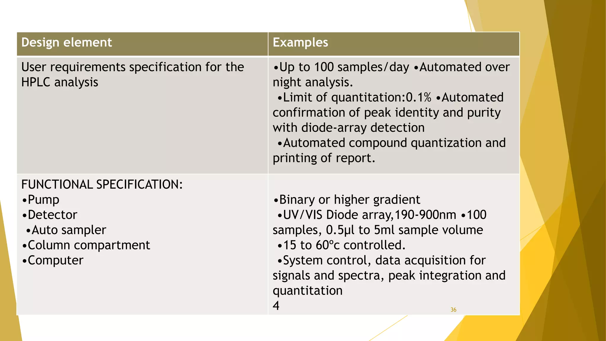
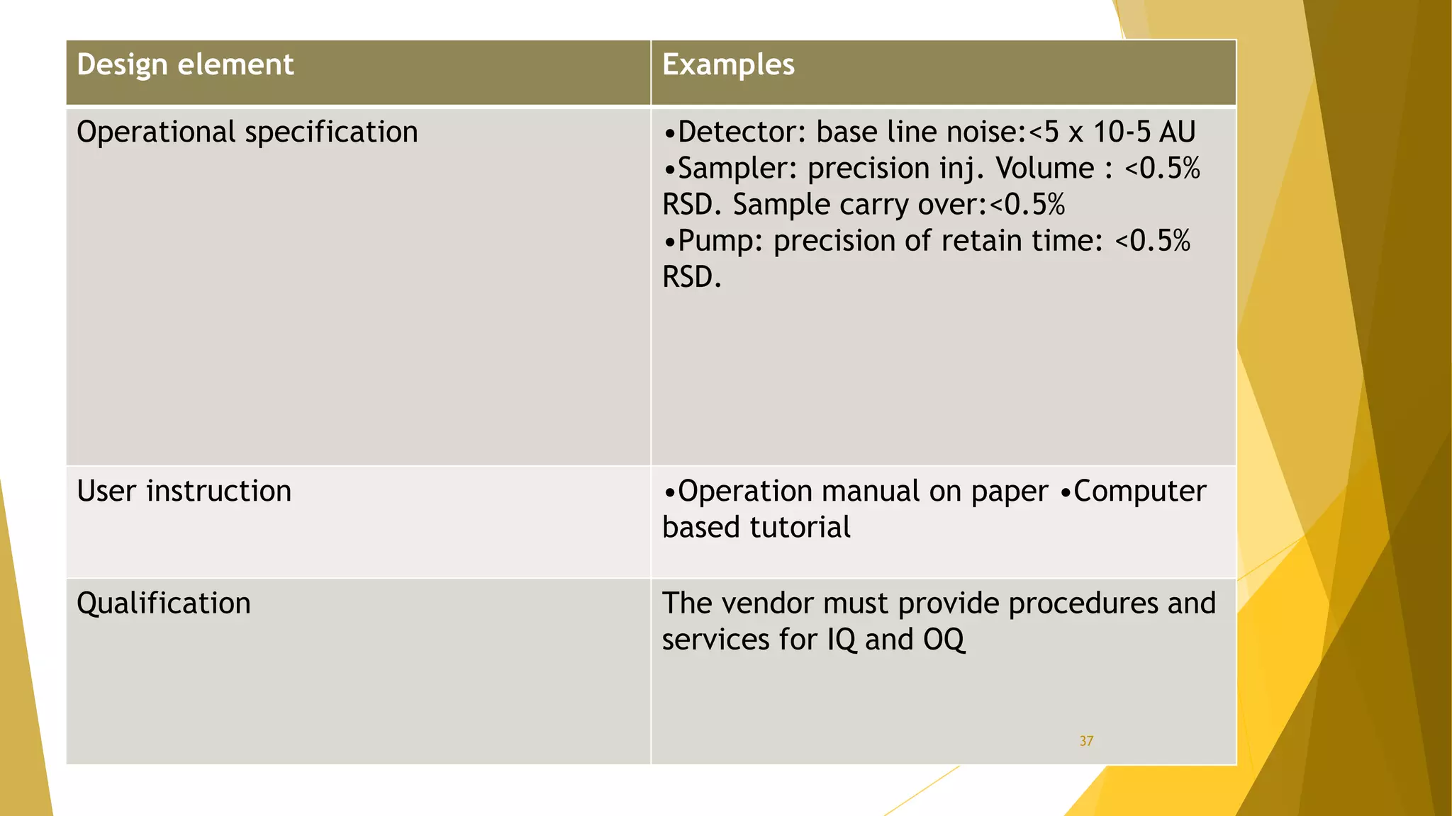
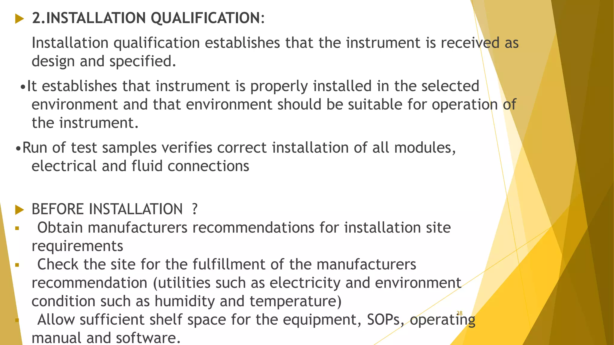
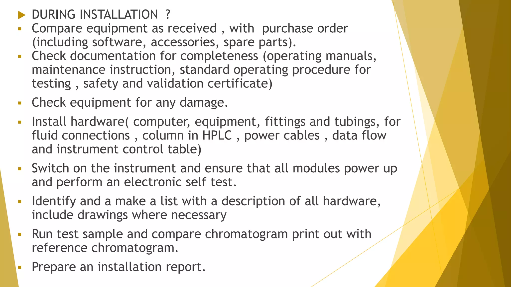
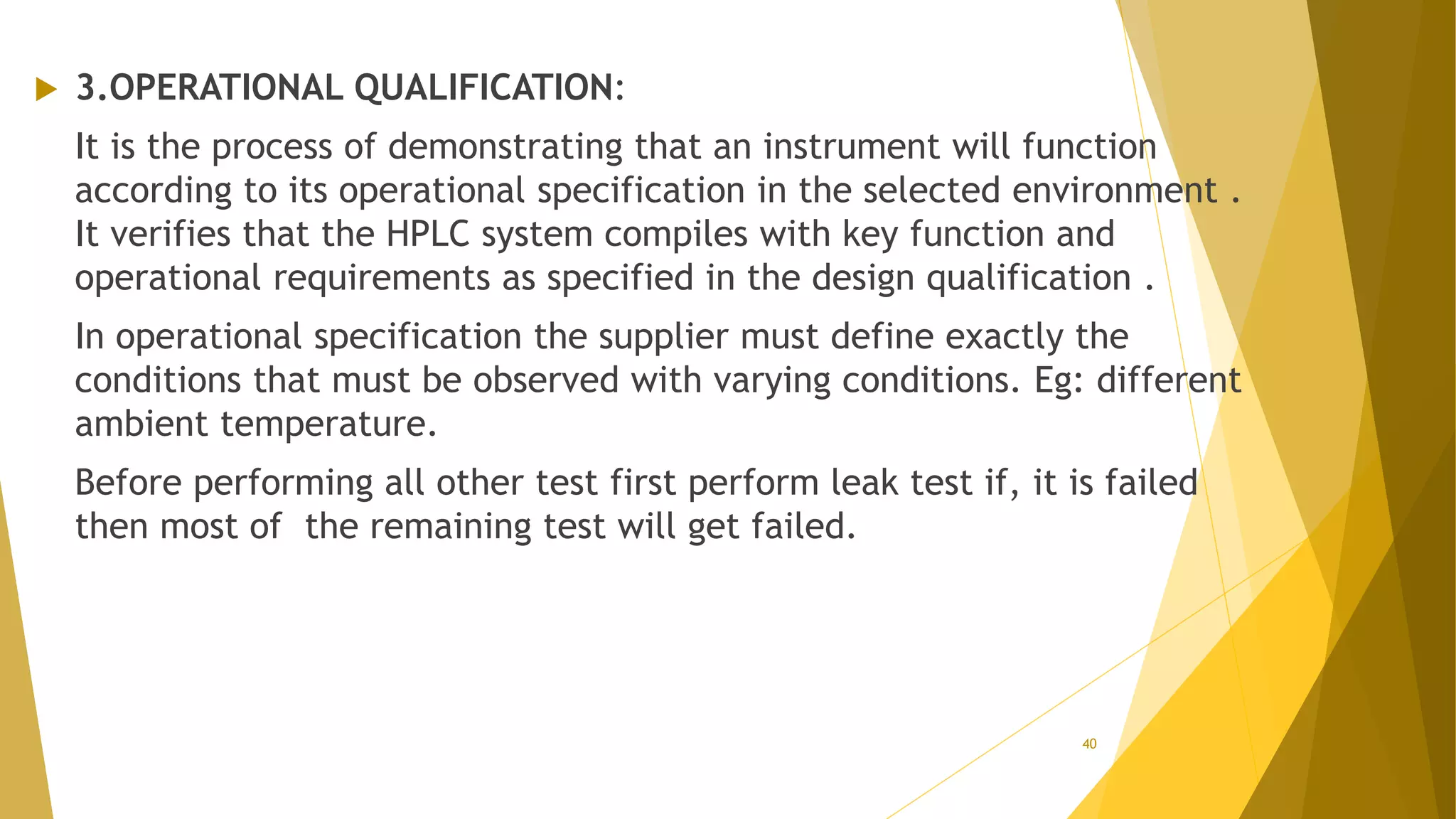
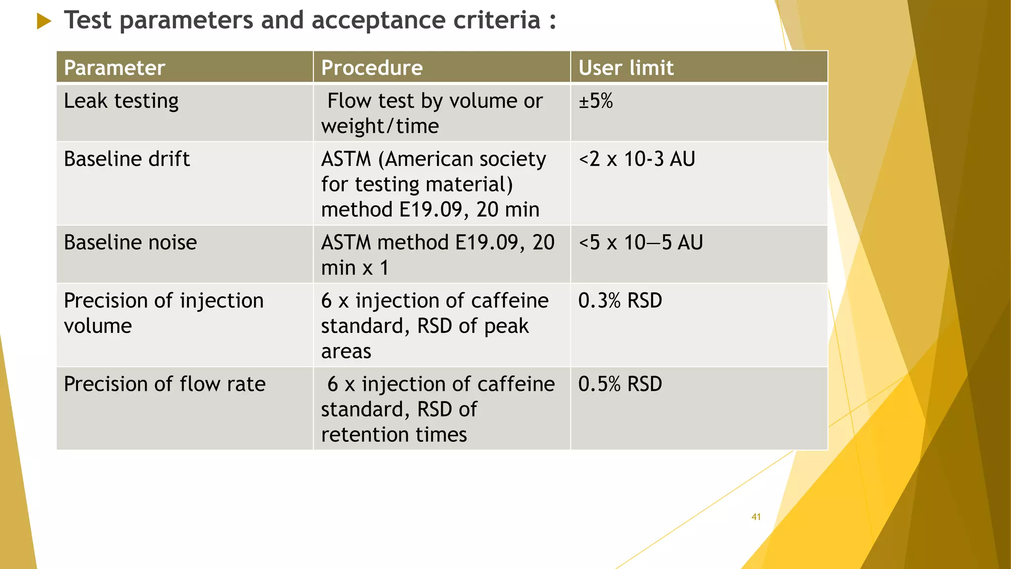
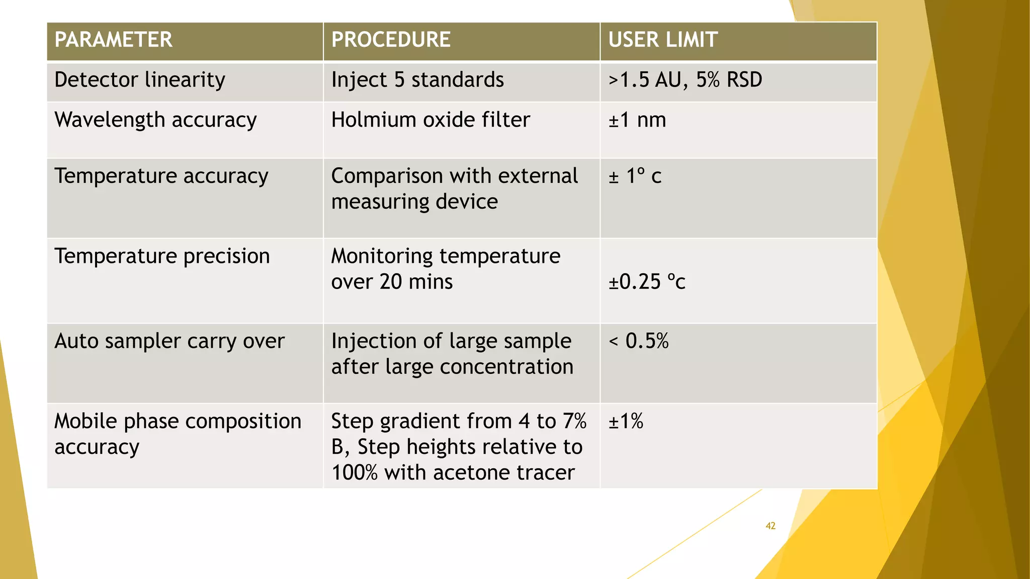
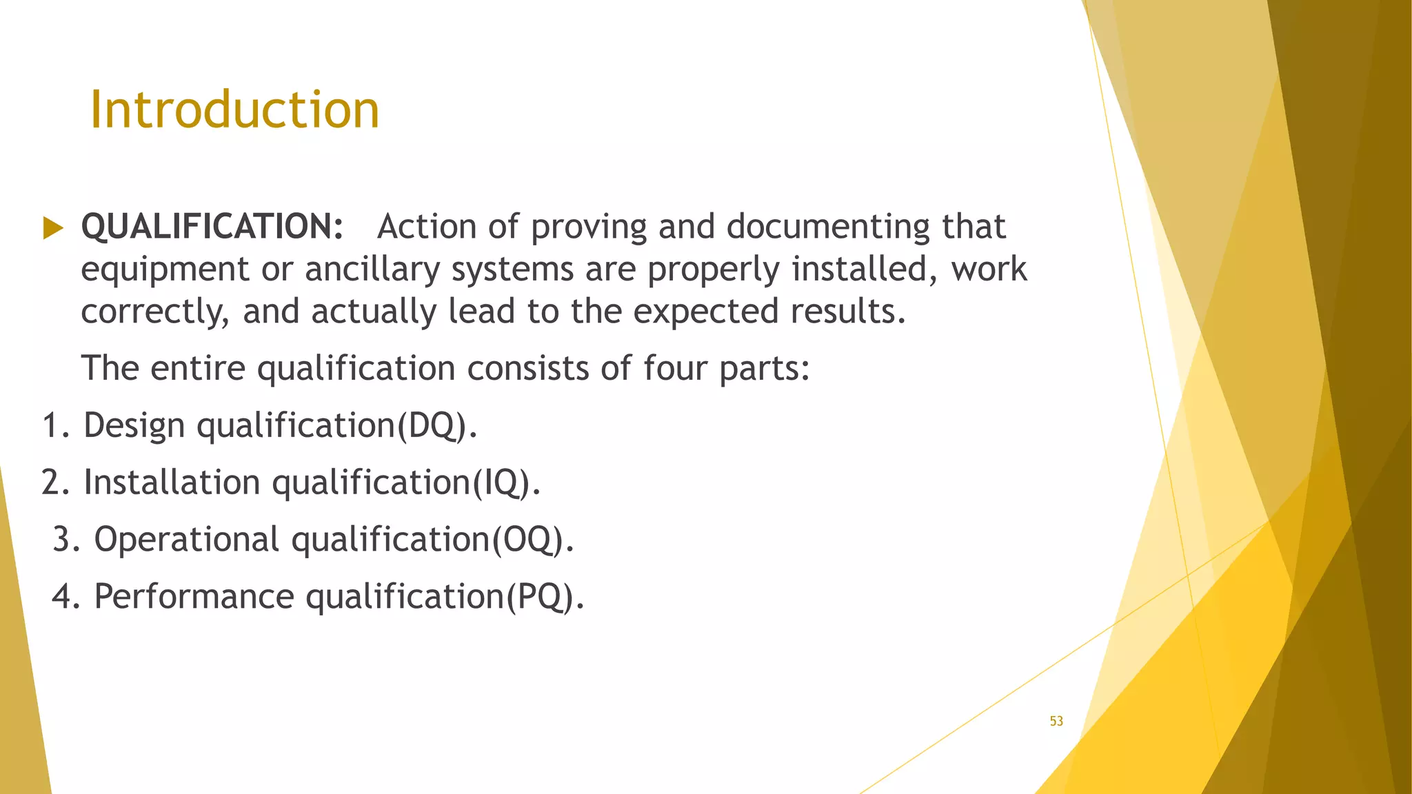
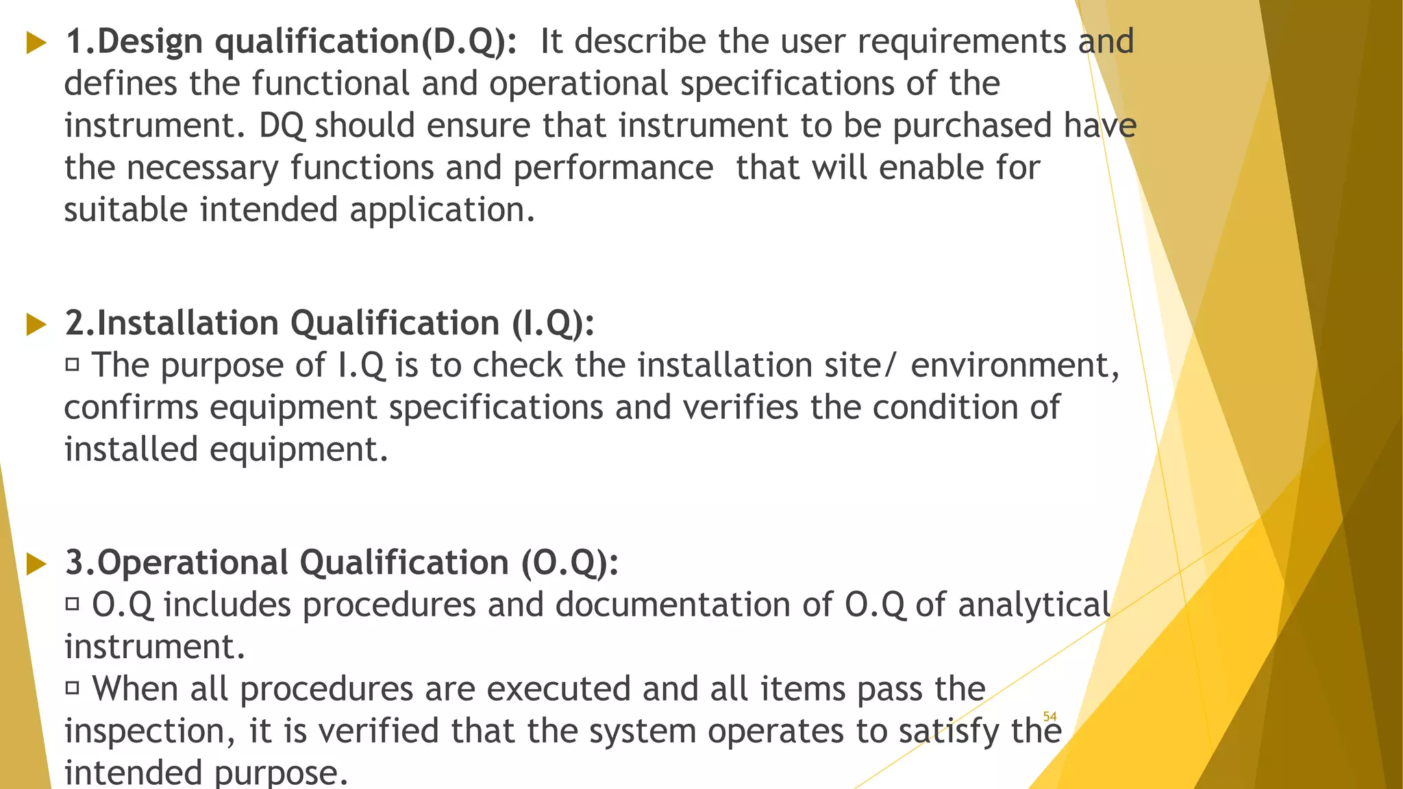
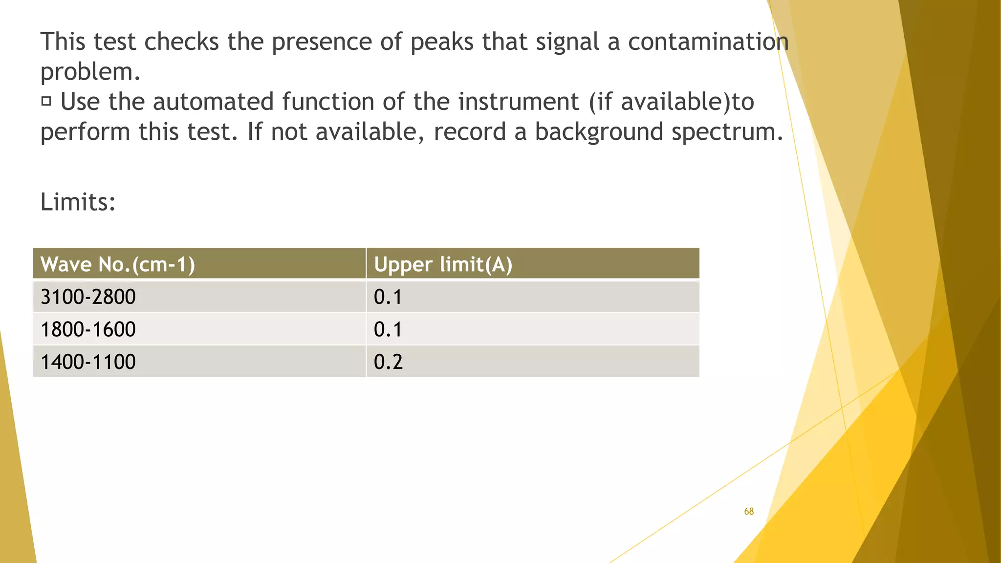
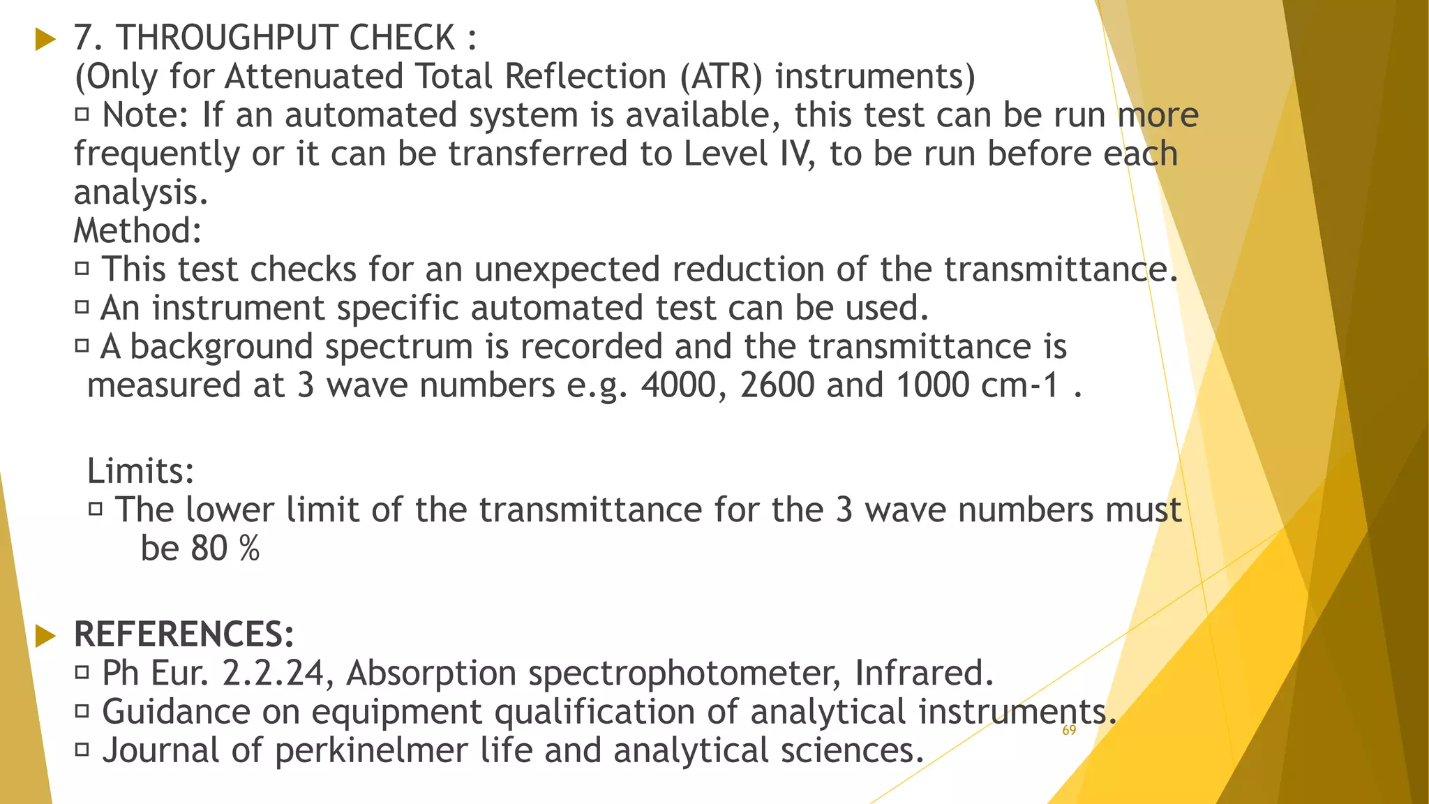
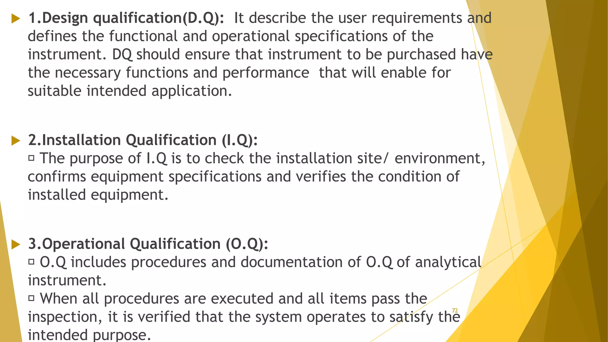
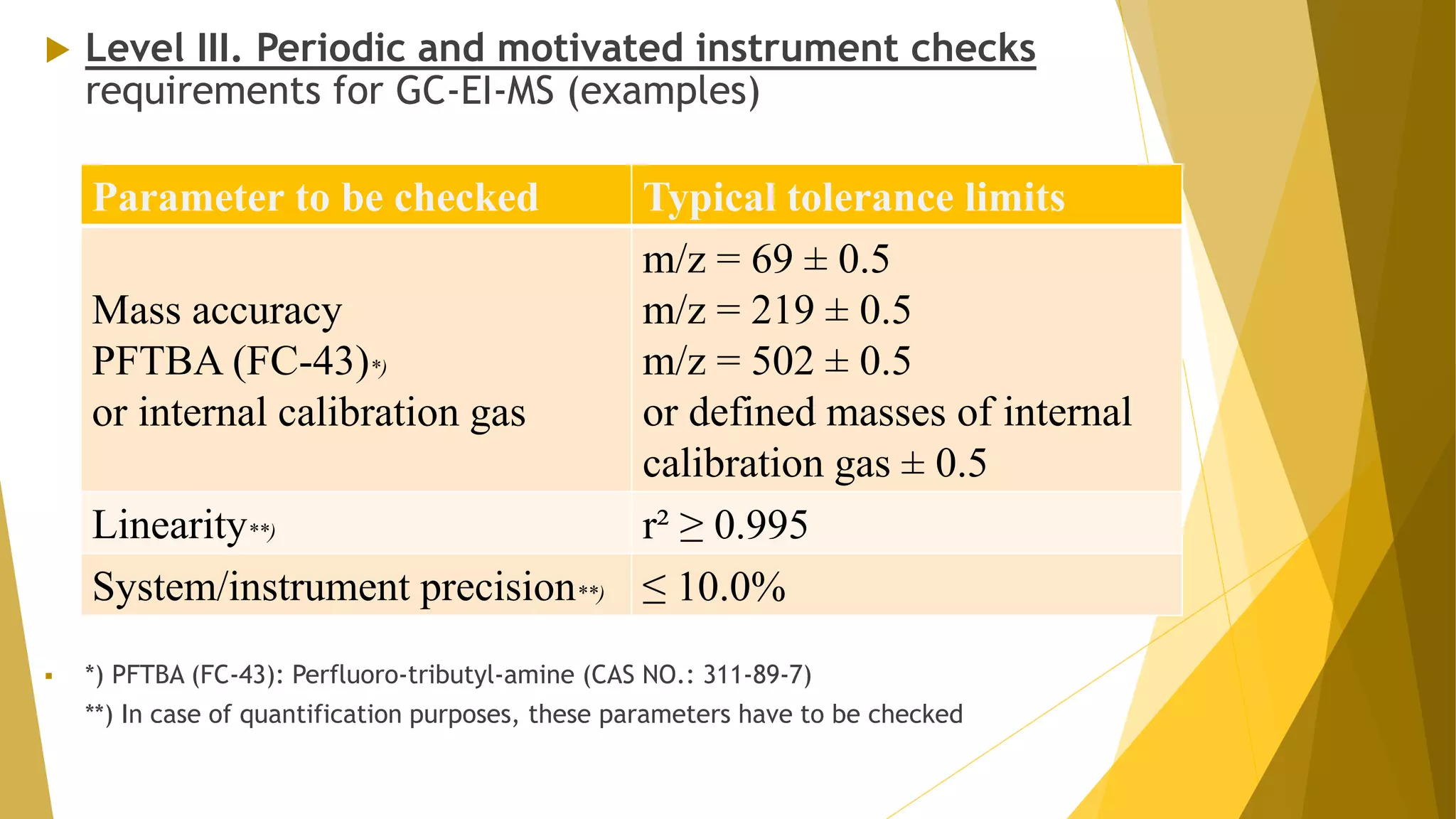
In this slide contains definition and details of Qualification Of HPLC
Presented by: KHALID KUWAITY (Department of pharmaceutical analysis).RIPER, anantapur
In this slide contains introduction, qualification, preventive maintenance, requalification method.
Presented by: Malarvannan M (Department of pharmaceutical analysis).RIPER, anantapur
University Institute of Pharmaceutical Sciences is a flag bearer of excellence in Pharmaceutical education and research in the country. Here is another initiative to make study material available to everyone worldwide. Based on the new PCI guidelines and syllabus here we have a presentation dealing with qualifications of HPLC which is the " High Performance Liquid Chromatography".
Thank you for reading.
Hope it was of help to you.
UIPS,PU team
It is process of “Establishing documentary evidence that provide a high degree of assurance that a specific process will consistently produce a product meeting its predetermined specifications and quality attributes”.
In the pharmaceutical industry, it is very important that in addition to final testing and compliance of products, it is also assured that the process will consistently produce the expected results.
Validation is action of proving in accordance with the principles of good manufacturing practices, that any procedure, process, equipment, material, activity or system actually leads to expected results.
Cleaning validation is documented evidence with a high degree assurance that one can consistently clean a system or a piece of equipment to predetermined and acceptable limits.
The primary regulatory concern driving the need for cleaning validation is cross contamination of the desired drug substance either by other API from previous batch runs or by residues from the cleaning agents used.
The prime purpose of validating a cleaning process is to ensure compliance with federal and other standard regulations
1. Cross contamination with active ingredients
Contamination of one batch of product with significant levels of residual active ingredients from previous batch cannot be tolerated.
In addition to the obvious problems posed by subjecting consumers or patients to unintended contaminants, potential clinically significant synergistic interactions between pharmacologically active chemicals are a real concern.
2. Contamination with unintended materials or compounds
While inert ingredients used in drug products are generally recognized as safe for human consumption, the routine use, maintenance and cleaning of equipment's provide the potential contamination with such items as equipment parts, lubricants and chemical cleaning agents3. Microbiological contamination
Maintenance , cleaning and storage conditions may provide adventitious microorganisms with the opportunity to proliferate within the processing equipment.
Analytical method validation as per ich and usp shreyas B R
Analytical method validation is a process of documenting/ proving that an analytical method provides analytical data acceptable for the intended use.After the development of an analytical procedure, it is must important to assure that the procedure will consistently produce the intended a precise result with high degree of accuracy. The method should give a specific result that may not be affected by external matters. This creates a requirement to validate the analytical procedures. The validation procedures consists of some characteristics parameters that makes the method acceptable with addition of statistical tools.
QUALIFICATION OF MANUFACTURING EQUIPMENTSANKUSH JADHAV
it gives the information about qualification of various manufacturing equipment which is used into the pharmaceutical labs. (only for information purpose)
In this slide contains details about Pharmaceutical validation of water system
Presented by: K VENKATSAI PRASAD (Department of pharmaceutical analysis and quality assurance).RIPER, anantapur
Qualification of Dissolution Test Apparatus and Validation of Utility System this presentation will help to enhance your knowledge in validation and qualification area.
In this slide contains Introduction, overview and details of FACTORY ACCEPTANCE TEST
Presented by: P.NARESH (Department of pharmaceutical analysis).RIPER, anantapur
What is IPQC & IPQC Test
Appearance
Drug content determination
pH
Sensitivity test
Spreadability
Rate of absorption
Extrudability
Consistency Test
Rheology & Viscosity
Performance qualification of High performance liquid chromatography Atchaya Thalapathy
Performance qualification is done consistently demonstrate the performance of instrument according to appropriate specifications for it's daily use.
PQ is always carried in conditions that are similar to routine sample analysis.
It means preferring same conditions for analysis, same column and same test compounds.
So performance qualification gives stability of instrument which contribute for result analysis
Aseptic / sterile - “ A state of control attained by using an aseptic work area and performing activities in a manner that precludes microbiological contamination of the exposed sterile product”
Validation of aseptic process should be designed to provide assurance through appropriate testing that all phases and activities of the process remain sterile and it is controlled within the predetermined parameters.
Drug product, container, and closure are subject to sterilization separately, and then brought together.
Operation “Blue Star” is the only event in the history of Independent India where the state went into war with its own people. Even after about 40 years it is not clear if it was culmination of states anger over people of the region, a political game of power or start of dictatorial chapter in the democratic setup.
The people of Punjab felt alienated from main stream due to denial of their just demands during a long democratic struggle since independence. As it happen all over the word, it led to militant struggle with great loss of lives of military, police and civilian personnel. Killing of Indira Gandhi and massacre of innocent Sikhs in Delhi and other India cities was also associated with this movement.
Model Attribute Check Company Auto PropertyCeline George
In Odoo, the multi-company feature allows you to manage multiple companies within a single Odoo database instance. Each company can have its own configurations while still sharing common resources such as products, customers, and suppliers.
Read| The latest issue of The Challenger is here! We are thrilled to announce that our school paper has qualified for the NATIONAL SCHOOLS PRESS CONFERENCE (NSPC) 2024. Thank you for your unwavering support and trust. Dive into the stories that made us stand out!
The Indian economy is classified into different sectors to simplify the analysis and understanding of economic activities. For Class 10, it's essential to grasp the sectors of the Indian economy, understand their characteristics, and recognize their importance. This guide will provide detailed notes on the Sectors of the Indian Economy Class 10, using specific long-tail keywords to enhance comprehension.
For more information, visit-www.vavaclasses.com
How to Make a Field invisible in Odoo 17Celine George
It is possible to hide or invisible some fields in odoo. Commonly using “invisible” attribute in the field definition to invisible the fields. This slide will show how to make a field invisible in odoo 17.
The French Revolution, which began in 1789, was a period of radical social and political upheaval in France. It marked the decline of absolute monarchies, the rise of secular and democratic republics, and the eventual rise of Napoleon Bonaparte. This revolutionary period is crucial in understanding the transition from feudalism to modernity in Europe.
For more information, visit-www.vavaclasses.com
Palestine last event orientationfvgnh .pptxRaedMohamed3
An EFL lesson about the current events in Palestine. It is intended to be for intermediate students who wish to increase their listening skills through a short lesson in power point.
Students, digital devices and success - Andreas Schleicher - 27 May 2024..pptxEduSkills OECD
Andreas Schleicher presents at the OECD webinar ‘Digital devices in schools: detrimental distraction or secret to success?’ on 27 May 2024. The presentation was based on findings from PISA 2022 results and the webinar helped launch the PISA in Focus ‘Managing screen time: How to protect and equip students against distraction’ https://www.oecd-ilibrary.org/education/managing-screen-time_7c225af4-en and the OECD Education Policy Perspective ‘Students, digital devices and success’ can be found here - https://oe.cd/il/5yV
The Art Pastor's Guide to Sabbath | Steve ThomasonSteve Thomason
What is the purpose of the Sabbath Law in the Torah. It is interesting to compare how the context of the law shifts from Exodus to Deuteronomy. Who gets to rest, and why?
Welcome to TechSoup New Member Orientation and Q&A (May 2024).pdfTechSoup
In this webinar you will learn how your organization can access TechSoup's wide variety of product discount and donation programs. From hardware to software, we'll give you a tour of the tools available to help your nonprofit with productivity, collaboration, financial management, donor tracking, security, and more.
Ethnobotany and Ethnopharmacology:
Ethnobotany in herbal drug evaluation,
Impact of Ethnobotany in traditional medicine,
New development in herbals,
Bio-prospecting tools for drug discovery,
Role of Ethnopharmacology in drug evaluation,
Reverse Pharmacology.
3. Introduction
QUALIFICATION: Action of proving and documenting that
equipment or ancillary systems are properly installed, work
correctly, and actually lead to the expected results.
The entire qualification consists of four parts:
1. Design qualification(DQ).
2. Installation qualification(IQ).
3. Operational qualification(OQ).
4. Performance qualification(PQ).
3
4. 1.Design qualification(D.Q): It describe the user requirements and
defines the functional and operational specifications of the
instrument. DQ should ensure that instrument to be purchased have
the necessary functions and performance that will enable for
suitable intended application.
2.Installation Qualification (I.Q):
The purpose of I.Q is to check the installation site/ environment,
confirms equipment specifications and verifies the condition of
installed equipment.
3.Operational Qualification (O.Q):
O.Q includes procedures and documentation of O.Q of analytical
instrument.
When all procedures are executed and all items pass the
inspection, it is verified that the system operates to satisfy the
intended purpose.
4
5. 4.Performance Qualification (P.Q):
The objective is to ensure that the instrument is
performing within specified limits.
Hence documented verification that the equipment and
ancillary systems, as connected together, can perform
effectively and reproducibly based on the approved
process
method and specifications.
6. Qualification of Gas Chromatography
Level I. Selection Of Instruments & Suppliers
At level I of the qualification of a gc equipment(selection of
instruments and suppliers)
It is recommended to select a manufacture of gc that can satisfy the
needs of the laboratory and works under ISO 9001 certification
Level II of Equipment Qualification:
Installation and release for use
It is recommended to check all requirements set during the selection
of the instrument, and
calibration should be performed before putting into service by an
accredited external service supplier, or Internally by appropriately
qualified personnel, using certified reference buffers according to an
approved procedure.
6
7. Level III. Periodic and motivated instrument
Checks Examples of requirements for GC instruments with FID
7
instrument module
Parameter to be
checked
Typical tolerance limit
1. Inlet system
1.1 Injector leak test
1.2. Pressure/flow
accuracy and stability
1.3. Repeatability of
injection (overall test 1) -
In split mode
-In split less mode
1.4. Injector temperature
accuracy and stability
1.5. Carry-over (overall
test 3)
Pressure drop ≤ 15 kPa
within 5 minutes
Covered by overall test
1
RSD ≤ 3.0%
RSD ≤ 3.0%
Covered by overall test
2
≤ 0.2
8. instrument module Parameter to be
checked
Typical tolerance limit
2. Oven
2.1. Repeatability of
oven
temperature
characteristics
Covered by overall test
2
3. FID detector
3.1. Linearity (overall
test 3)
3.2. Constant detector
response
3.3. Noise
3.3. Drift
r 2 ≥ 0.999
Covered by overall
test 1 or 2
8
9. Level III. Periodic and motivated instrument checks
Practical examples of tests and their associated tolerance limits for several
parameters related to the performance of the different modules of a
GC are presented below.
These examples can be considered by the OMCLs as possible
approaches to perform the Level III of the equipment qualification
process: “Periodic and motivated instrument checks”.
Several tests are proposed to check various parameters at the
same time (overall tests).
In order to run the tests in a more economical way, other suitable
solutions can be used, as for example, the “Grob Test” mixture,
available from different suppliers (e.g. Alltech, Sigma, Thames
Restek).
This commercial solution should be appropriate to the column
material used.
It is recommended to run the overall tests by using always the
same test column, exclusively dedicated to qualification purposes,
to guarantee reproducible conditions 9
10. 1. Inlet system The following tests are proposed for the
periodic and motivated check of the GC Inlet System.
1.1. Injector leak test
Method:
If not otherwise specified by the instrument manufacturer,
the leak test is carried out according to the procedure laid
down in the instrument manual or by the built in automatic
leak check procedure of the instrument.
Otherwise use the test described below:
Disconnect the column from the injector and close the
injector outlet with a sealed cap.
Close the septum purge and the bypass.
Adjust the flow and pressure controller to the maximal
possible value of the pressure gauge.
10
11. Adjust the flow controller to zero.
Read the pressure after 1 minute and record the value.
Record the pressure after 5 minutes.
Limits:
Pressure drop ≤ 15 kPa within 5 minutes.
1.2. Inlet pressure/flow accuracy and stability
A direct measurement of these parameters was not deemed
practical or necessary, but the optimal conditions of flow/pressure
can be verified by the overall test 1.
Limits: Refer to overall test 1
1.3. Repeatability of injection
The verification of this parameter is covered by the overall
test 1.
This test is to be performed in both split and split less mode.
Limits: Refer to overall test 1.
12. 1.4. Injector temperature accuracy and stability
Due to the fact that the temperature cannot be reliably measured
without opening and modifying the system and due to the difficulties of
introducing a probe inside this module, the verification of this
parameter is considered to be covered by the overall test 2.
Limits: Refer to overall test 2.
1.5. Injector carry over
After having injected the solutions for the linearity test of the FID
detector, in increasing order, inject the blank and measure the peaks
that correspond to the major peaks (= analytes) in the linearity
solutions.
The verification of this parameter is covered by the overall
test 3.
Limits: Refer to overall test 3
12
13. 2. OVEN
2.1. Repeatability of the oven temperature
characteristics
Due to the fact that the temperature cannot be reliably measured
without opening and modifying the system conditions and that even
when introducing a probe inside the oven, its location would not
reflect the real temperature conditions at all points, the verification
of this parameter is covered by the overall tests 2A and 2B.
Limits: Refer to overall test 2.
3. FID DETECTOR
The following tests are proposed for the periodic and motivated
check of the GC FID detector.
3.1. FID detector linearity
Increasing amounts of analyte are injected and a linear response
should be obtained.
The verification of this parameter is covered by the overall test 3.
Limits: Refer to overall test 3. 13
14. 3.2. Constant FID detector response
The proper and reproducible functioning of the FID can be
demonstrated by checking the peak areas obtained from a predefined
standard solution.
The verification of this parameter is covered by the overall test
1 or 2.
Limits: Refer to overall test 1 or 2.
3.3. Fid detector noise and drift
If the instrument has a built-in automatic system for the verification
of the noise and drift, follow the manufacturer’s instructions and
apply the defined acceptance criteria.
Otherwise, use the test described below:
Settings:
Column installed
Suitable flow, depending on column length/diameter
No injection
Oven temperature: 40°C
Detector on and heated at working temperature (270- 300°C)
15. 3.3. Fid detector noise and drift
If the instrument has a built-in automatic system for the
verification of the noise and drift, follow the manufacturer’s
instructions and apply the defined acceptance criteria.
Otherwise, use the test described below:
Settings:
Column installed
Suitable flow, depending on column length/diameter
No injection
Oven temperature: 40°C
Detector on and heated at working temperature (270- 300°C)15
16. Method:
After stabilisation of the system, record the signal for 15
minutes.
Noise: evaluate 10 periods of 1 minute and calculate the mean
value.
Drift: Evaluate the slope of the baseline over the 15 minutes.
Limits:
The acceptance criteria for these parameters have to be
chosen in accordance with the instrument vendor’s instructions
and the intended use of the instrument.
If no instructions are given, the user has to pre-define these
acceptance criteria by taking into account the previous
experience and the intended use of the instrument.
No fixed values can be pre-defined in this guideline due to the
high variety of integration systems used and consequently the
acceptance criteria may be expressed in different units (voltage,
current, arbitrary units per time).
17. OVERALL TEST 1
The overall test 1 covers the following parameters:
- Pressure/flow accuracy and stability in the inlet system:
Retention time repeatability
- Repeatability of injection: peak area precision
- In split mode
- In split less mode
The test may be combined with overall test 3.
Split mode:
Test solution: 1-octanol in n-hexane 1% (v/v)
Settings:
Column: SPB-1 (30m x 0.32mm ID x 0.25µm film)
Carrier gas: He
Velocity: 25cm/sec
Split: 1:100
Injection: 1µl 17
18. Injector temperature: 220°C
Oven temperature: 100°C isotherm
Detector temperature: 300°C
Runtime: 8 min
Retention time of 1-octanol: about 5 min
Split less mode:
Stock solution: 1-octanol in n-hexane 1% (v/v)
Test solution: Dilute 10 ml of the stock solution with nhexane
to 100 ml (corresponds to 1µl/ml of 1-octanol in nhexane)
Settings:
Column: SPB-1, 30m, 0.32mm ID, 0.25µm film
Carrier: He
Velocity: 30cm/sec
Split less injection: purge valve closed during 2 min
Injection: 0.2µl of the test solution
19. Injector Temperature: 220°C
Oven Temperature: Initial 60°C for 4 min, 15°C/min. up to
135°C, final time 1min
Detector temperature: 300°C
Runtime: 9.5 min
Retention time of 1-octanol: about 8 min
Method:
Carry out 6 consecutive injections of the test solution and
calculate the RSD of the different peak areas and retention
times.
Limits:
Retention time repeatability: the RSD of the retention times
should be ≤ 2.0%
Peak area precision (split and split less mode): the RSD of the
peak areas should be ≤ 3.0%
20. OVERALL TEST 2
The overall test 2 covers the following parameters:
- Injector, oven and detector temperature accuracy and
stability: retention time repeatability
- Two alternative tests are proposed
1.Overall test 2A
Test solution:
0.035 ml 1-octanol
0.035 ml 2-octanone
0.035 ml 2,6-dimethylanilin
0.035 ml n-tridecane
0.035 ml n-tetradecane
35 mg n-eicosane
Dissolved in 50 ml Dichloromethane
21. Settings:
Column: SPB-1 (30m x 0.32mm ID x 0.25µm film)
Carrier gas: Helium
Velocity: 25 cm/s
Split: 1:100
Injection volume: 1 µl
Injector temperature: 220°C
Detector: FID
Detector temperature: 300°C
Gradient programme: 60°C (4 min), 5°C/min, 270°C (3 min)
Method:
Inject the solution twice and calculate the relative retention times in
relation to n-eicosane (RRT = 1)
The above table shows the approximately expected relative retention
times. 21
22. Method:
Inject the solution twice and calculate the relative retention
times in relation to n-eicosane (RRT = 1)
The above table shows the approximately expected relative
retention times.
Limits: The RSD of each RRT from two consecutive
injections
should be ≤ 1.0% 22
Analyte 1-octanol 2-octanone N-tridecane N-tetra
decan
RRT 0.30 0.22 0.52 0.60
23. 2.Overall test 2B
Test Solution: 1.0% (W/W) n-Nonane and Hexadecane in
Tetradecane.
Settings:
Column: Ultra-1 (25m x 0.32mm ID x 0.52µm film)
Injection volume: 1 µl
Solvent: Tetradecane
Oven temperature: 110°C
Gradient programme: 110°C, 20°C/min, 180°C (final time: 3.5
min)
Detector temperature: 250°C
Injector temperature: 200°C
Detector: FID
24. Flow rates:
Carrier gas (Helium): 2 ± 0.2 ml/min
Hydrogen: 30 ± 1.0 ml/min
Air: 400 ± 20.0 ml/min
Makeup (Nitrogen): 28 ± 1.0 ml/min
Split ratio: 15
Split vent: 30 ± 3.0 ml/min
Septum purge: 3-5 ml/min
Method:
Allow the system to equilibrate
Injection sequence:
1) Blank (Tetradecane)
2) 6 replicates of the test solution.
24
25. Calculate the mean of the retention times and peak areas and the
relative standard deviation of n-Nonane and n-Hexadecane
Limits:
Retention time repeatability: RSD of the peak retention times of the
6 replicates ≤ 2%
Retention time (Rt) accuracy: for this example, the retention time
ranges shown in the table below are proposed. Nevertheless, individual
ranges should be predefined by the laboratory depending on the
column used (e.g. Rt ± 0.2 min).
OVERALL TEST 3
This test is a modified version of the overall test 1 to be used for
the verification of:
- Detector linearity: linearity of the areas recorded
- Injector carry-over: area recorded in the blank run
It is described for both split and split less mode and may be combined
with overall test 1.
26. Split mode:
Test solution: 1-octanol in n-hexane 1% (v/v)
Prepare further reference solutions by diluting the test solution as
described below.
Settings: see overall test 1
Injection sequence:
5.0 ml of the test solution diluted to 25.0 ml with n-hexane (2
µl/ml): 2 injections 10.0 ml of the test solution diluted to 25.0 ml with
nhexane (4 µl/ml): 2 injections
15.0 ml of the test solution diluted to 25.0 ml with n-hexane (6
µl/ml): 2 injections
20.0 ml of the test solution diluted to 25.0 ml with n-hexane (8
µl/ml): 2 injections
If combined with overall test 1 for repeatability: test solution (10
µl/ml): 6 injections n-hexane as blank (carry over) 26
27. Split less mode:
Stock solution: 1-octanol in n-hexane 1% (v/v)
Test solution: Dilute 10 ml of the stock solution with nhexane to 100 ml
(corresponds to 1µl/ml of 1-octanol in nhexane).
Prepare further reference solutions by diluting the test solution with n-
hexane.
Settings: see overall test 1
Injection sequence:
5.0 ml of the test solution diluted to 25.0 ml with n-hexane (0.2 µl/ml): 2
injections
10.0 ml of the test solution diluted to 25.0 ml with n-hexane (0.4 µl/ml): 2
injections
15.0 ml of the test solution diluted to 25.0 ml with n-hexane (0.6
µl/ml): 2 injections
20.0 ml of the test solution diluted to 25.0 ml with n-hexane (0.8 µl/ml): 2
injections
If combined with overall test 1 for repeatability: test solution (1 µl/ml): 6
injections n-hexane as blank (carry over)
28. Linearity: coefficient of correlation of the calibration line
obtained
with the reference solutions and the test solution: r 2 ≥ 0.999.
Carry-over: the percentage of the peak area corresponding to the
analyte in the blank solution should be ≤ 0.2% of the peak area of
this analyte in the chromatogram obtained with the solution with
the highest concentration within the sequence
28
29. Level IV. In-use instrument checks Examples of requirements for
GC instruments with FID
29
Parameter to be checked Typical tolerance limit
1. System suitability check for the
method
According to Ph. Eur. or MAH
dossier or validated in-house
method
2. Peak area precision
RSD ≤ 3.0% unless otherwise
prescribed*
3. Retention time repeatability RSD ≤ 2.0%
4. Sensitivity (where relevant, e.g.
for related substances tests)
According to Ph. Eur. or MAH dossier
or validated in-house method
30. Reference:
Ph.Eur.2.2.35 chromatography; gas chromatography
Guidance on equipment qualification of analytical instruments
Journal of Perkin Elmer life & analytical science
32. Introduction
QUALIFICATION: Action of proving and documenting that
equipment or ancillary systems are properly installed, work
correctly, and actually lead to the expected results.
The entire qualification consists of four parts:
1. Design qualification(DQ).
2. Installation qualification(IQ).
3. Operational qualification(OQ).
4. Performance qualification(PQ).
32
33. 1.Design qualification(D.Q): It describe the user requirements and
defines the functional and operational specifications of the
instrument. DQ should ensure that instrument to be purchased have
the necessary functions and performance that will enable for
suitable intended application.
2.Installation Qualification (I.Q):
The purpose of I.Q is to check the installation site/ environment,
confirms equipment specifications and verifies the condition of
installed equipment.
3.Operational Qualification (O.Q):
O.Q includes procedures and documentation of O.Q of analytical
instrument.
When all procedures are executed and all items pass the
inspection, it is verified that the system operates to satisfy the
intended purpose.
33
34. 4.Performance Qualification (P.Q):
The objective is to ensure that the instrument is
performing within specified limits.
Hence documented verification that the equipment and
ancillary systems, as connected together, can perform
effectively and reproducibly based on the approved
process method and specifications.
35. Qualification of HPLC
1. Design qualification:
35
Design element example
Maintenance •Vendor must deliver maintenance
procedure and recommended schedule
•Instrument must include early
maintenance feedback for timely
exchange of most important
maintenance parts. •Maintenance
procedure must be supplied on
multimedia CD ROM
Intended use Analysis of drug components and
impurities.
36. Design element Examples
User requirements specification for the
HPLC analysis
•Up to 100 samples/day •Automated over
night analysis.
•Limit of quantitation:0.1% •Automated
confirmation of peak identity and purity
with diode-array detection
•Automated compound quantization and
printing of report.
FUNCTIONAL SPECIFICATION:
•Pump
•Detector
•Auto sampler
•Column compartment
•Computer
•Binary or higher gradient
•UV/VIS Diode array,190-900nm •100
samples, 0.5µl to 5ml sample volume
•15 to 60ºc controlled.
•System control, data acquisition for
signals and spectra, peak integration and
quantitation
4 36
37. Design element Examples
Operational specification •Detector: base line noise:<5 x 10⁻⁵ AU
•Sampler: precision inj. Volume : <0.5%
RSD. Sample carry over:<0.5%
•Pump: precision of retain time: <0.5%
RSD.
User instruction •Operation manual on paper •Computer
based tutorial
Qualification The vendor must provide procedures and
services for IQ and OQ
37
38. 2.INSTALLATION QUALIFICATION:
Installation qualification establishes that the instrument is received as
design and specified.
•It establishes that instrument is properly installed in the selected
environment and that environment should be suitable for operation of
the instrument.
•Run of test samples verifies correct installation of all modules,
electrical and fluid connections
BEFORE INSTALLATION ?
Obtain manufacturers recommendations for installation site
requirements
Check the site for the fulfillment of the manufacturers
recommendation (utilities such as electricity and environment
condition such as humidity and temperature)
Allow sufficient shelf space for the equipment, SOPs, operating
manual and software.
38
39. DURING INSTALLATION ?
Compare equipment as received , with purchase order
(including software, accessories, spare parts).
Check documentation for completeness (operating manuals,
maintenance instruction, standard operating procedure for
testing , safety and validation certificate)
Check equipment for any damage.
Install hardware( computer, equipment, fittings and tubings, for
fluid connections , column in HPLC , power cables , data flow
and instrument control table)
Switch on the instrument and ensure that all modules power up
and perform an electronic self test.
Identify and a make a list with a description of all hardware,
include drawings where necessary
Run test sample and compare chromatogram print out with
reference chromatogram.
Prepare an installation report.
40. 3.OPERATIONAL QUALIFICATION:
It is the process of demonstrating that an instrument will function
according to its operational specification in the selected environment .
It verifies that the HPLC system compiles with key function and
operational requirements as specified in the design qualification .
In operational specification the supplier must define exactly the
conditions that must be observed with varying conditions. Eg: different
ambient temperature.
Before performing all other test first perform leak test if, it is failed
then most of the remaining test will get failed.
40
41. Test parameters and acceptance criteria :
41
Parameter Procedure User limit
Leak testing Flow test by volume or
weight/time
±5%
Baseline drift ASTM (American society
for testing material)
method E19.09, 20 min
<2 x 10⁻³ AU
Baseline noise ASTM method E19.09, 20
min x 1
<5 x 10—5 AU
Precision of injection
volume
6 x injection of caffeine
standard, RSD of peak
areas
0.3% RSD
Precision of flow rate 6 x injection of caffeine
standard, RSD of
retention times
0.5% RSD
42. PARAMETER PROCEDURE USER LIMIT
Detector linearity Inject 5 standards >1.5 AU, 5% RSD
Wavelength accuracy Holmium oxide filter ±1 nm
Temperature accuracy Comparison with external
measuring device
± 1º c
Temperature precision Monitoring temperature
over 20 mins ±0.25 ºc
Auto sampler carry over Injection of large sample
after large concentration
< 0.5%
Mobile phase composition
accuracy
Step gradient from 4 to 7%
B, Step heights relative to
100% with acetone tracer
±1%
42
43. Baseline noise and drift:
•Drift and baseline noise are important factors for UV detectors.
Increased baseline noise considerably reduces the sensitivity, as it is not
possible to distinguish between low-level signals and noise. With
increased drift, it is more difficult to integrate the signals correctly
because the less stable the baseline is, the more inaccurate is
integration.
•The baseline noise of the detector mainly depends on the lamp. There
is a considerable increase in noise if an old lamp with poor light intensity
is used. This is also true when the flow cells is dirty. In addition make
sure that the flow cells free from gas bubbles.
•To measure the drift of a UV detector, also make sure that all measuring
conditions are constant. In addition, it is very important that the lamp
has been burning for several hours in the detector environment, avoid
direct sunlight.
•The lamp intensity decreases while the lamp is burning. Besides, the
lamp ages when it is turned on and off very often.
43
44. Evaluating baseline noise and drift:
•TO check noise, drift water is pumped through the cell at a flow
rate of 1ml/min. The UV signal is recorded at 254nm.
•To calculate noise the measuring signal is split into 20 intervals for
1min each. For each interval chromeleon calculates a regression
based on measured values, using the method of least square. The
limit should be between <2 x 10³ AU.
•To calculate the drift, chromeleon calculates a regression line from
all data points with in a range of 1-21mins based on the method of
least square. The slope of the regression line is the calculated drift.
The limit should be between <5 x 10—5 AU.
44
45. Precision of injection volume:
•Precision of injection volume is an important parameter for
accuracy of quantitation.
Evaluating precision of injection volume:
•Inject 6 standard caffeine solution and calculate height, area,
average height, average area, %RSD of height and %RSD of area
which gives precision of volume and the limit should be in
between 0.3% RSD.
Detector linearity:
•Linearity of a detector is a critical parameter to establish for
reliable and accurate quantitative results.
46. Evaluating detector linearity:
•A series of 5 traceable standards (caffeine solution of
concentration about 0.00035 to 0.35mg/ml) are injected and
evaluated. The detector linearity is calculated by determining the
peak area vs concentration. %RSD can also be calculated for
checking the detector linearity. The limit should be in between >1.5
AU, 5% RSD.
Wavelength accuracy:
•It is an important parameter for accuracy of quantitative and
qualitative analysis.
Evaluating wavelength accuracy:
•Traceable caffeine standard is used to determine the wavelength
accuracy. Caffeine is trapped in the flow cell and a programmable
timetable is used to determine the wavelength maxima (205nm) and
minima (273nm). The wavelength accuracy is determined as the
absolute difference between the measured and certified wavelength
values
46
47. Temperature accuracy: Temperature fluctuations of the solvent
and column can result in considerable retention time
fluctuations. Therefore, accuracy of the temperature is
important.
Evaluating temperature accuracy: 4 measuring points are used
to check the temperature accuracy of the column compartment.
The check is performed with column oven sequence. The
achieved temperature is measured with external calibrated
thermometer.
The achieved temperatures are compared to the set values. The
difference indicates the temperature accuracy and the limit
should be in between ± 1º c
Temperature precision: Monitor temperature for 20minutes and
limit should be in between ±0.25 ºc
48. Gradient mobile phase composition accuracy: It is important for
accurate quantitative analysis.
Evaluating gradient mobile phase composition accuracy: An
Acetone tracer is used to determine gradient mobile phase accuracy,
stability and linearity. Make 6 compositions of water+acetone in
concentration of 0%,20%,40%,60%,80% and 100% (20% increment).
Linear ramp down from 100% to 0% is performed where the
composition linearity is determined between ranges of 95,75 and
25%. All compositions accuracies are calculated as the absolute
difference between the mean composition at each set point and the
theoretical composition.
48
49. 4.Performance qualification:
It is the process of demonstrating that an instrument consistently
performs according to a specification appropriate for its routine
use.
Important here is the word consistently. The test frequency is
much higher than for OQ. Another difference is that PQ should
always be performed under conditions that are similar to routine
sample analysis. For a chromatogram this means using the same
column, the same analysis conditions and the same or similar test
compounds.
PQ should be performed on a daily basis or whenever the
instrument is used.
The test frequency of only depends on the stability of the
equipment but on everything in the system that may contribute to
analysis the result For a liquid chromatograph, this may be the
chromatographic column or a detectors lamp
49
50. The test criteria and the frequency should be determined during
the development and the validation of the analytical method. In
practice PQ mean system stability testing , where critical key
system performance characteristic are measured and compared
with documented , preset limit.
For example, a well characterized standard can be injected 5 or
6 times and the standard deviation of amounts are then
compared with predefined value
If the limits of detection and quantifications are critical, the
lamps intensity profile or the base line should be tested they
should use the same column and chemicals for the real sample.
51. Test should include:
•Precision of the amounts
•Precision of retention times
•Resolution between two peaks
•Peak width at half height
•Peak tailing
•Baseline noise
•Wavelength accuracy of the uv/vis wavelength detector,
preferably using built-in holmium – oxide filters
REFERENCES:
•Ph.Eur.2.2.35chromatography; High performance liquid chromatography
•Guidance on equipment qualification of analytical instruments
•Journal of Perkin Elmer life & analytical science
51
53. Introduction
QUALIFICATION: Action of proving and documenting that
equipment or ancillary systems are properly installed, work
correctly, and actually lead to the expected results.
The entire qualification consists of four parts:
1. Design qualification(DQ).
2. Installation qualification(IQ).
3. Operational qualification(OQ).
4. Performance qualification(PQ).
53
54. 1.Design qualification(D.Q): It describe the user requirements and
defines the functional and operational specifications of the
instrument. DQ should ensure that instrument to be purchased have
the necessary functions and performance that will enable for
suitable intended application.
2.Installation Qualification (I.Q):
The purpose of I.Q is to check the installation site/ environment,
confirms equipment specifications and verifies the condition of
installed equipment.
3.Operational Qualification (O.Q):
O.Q includes procedures and documentation of O.Q of analytical
instrument.
When all procedures are executed and all items pass the
inspection, it is verified that the system operates to satisfy the
intended purpose.
54
55. 4.Performance Qualification (P.Q):
The objective is to ensure that the instrument is
performing within specified limits.
Hence documented verification that the equipment and
ancillary systems, as connected together, can perform
effectively and reproducibly based on the approved
process
method and specifications.
55
56. QUALIFICATION OF IR
SPECTROPHOTOMETER
INTRODUCTION
The present document explains about “Qualification of
Equipment(IR Spectrophotometer)”,
It should be used in combination with it when planning,
performing and documenting the IR spectrophotometer qualification
process.
The document contains the Introduction and general forms for
Level I and II of qualification, which are common to all type of
instruments.
For FTIR spectrometers, an example has been added to give
instrument-specific proposals that may be used in combination with
the general requirements presented in the core document
“Qualification of Equipment”, when drawing up a Level I checklist.
56
57. The present annex contains instrument-related recommendations
on parameters to be checked at Level III and IV of qualification and
the corresponding typical acceptance limits, as well as practical
examples on the methodology that can be used to carry out these
checks.
Level I. Selection Of Instruments & Suppliers
Example of check-list (Non-Exhaustive)
Manufacturer:____________
Provider/ Distributor:___________
Name Of Instrument and Type: __________
57
58.
58
Attribute
(This list may be
adapted if
necessary)
Specifications
Benefits
(Instrument/
supplier)
Assessment
(Pass/Fail)
SPECTROPHOTO
METER
Detector range
The optical bench shall include a
DTGS detector with a frequency
range of 7400 to 350 cm-1
It shall include a
compressed
air interferometer
Spectral resolution
The instrument shall
come
with an air-cooled
standard
infrared source.
59. Attribute
(This list may be
adapted if
necessary)
Specifications
Benefits
(Instrument/
supplier)
Assessment
(Pass/Fail)
Wave number accuracy
The instrument shall have a
spectral resolution not
exceeding 1.0 cm-1
The interferometer shall have at least
four basic velocity levels: software
shall permit the selection of a greater
number of velocities between the basic
levels.
Wave number
accuracy shall be
better than +- 0.01
cm-1
The mirror’s greatest velocity
shall allow a speed of at least five
sweeps per second
The laser and infrared beams must be
coaxial to enable rapid, easy alignment
of the system, depending on the
samples or accessories
59
60. ughjhjkjk
Attribute
(This list may be
adapted if
necessary)
Specifications
Benefits
(Instrument/
supplier)
Assessment
(Pass/Fail)
The optical bench shall have
main experimentation module
with a device to allow purging
with nitrogen
At purchase, the main
experimentation module shall be
designed so it can receive 13 and
5 mm potassium bromide pellets
60
Notes: -
This check-list, containing examples of technical attributes that can
be taken into account in the selection of an instrument and supplier,
can be used in combination with the general check-list presented in
Level I in the core document “Qualification of Equipment”.
61. Level II of Equipment Qualification:
Installation and Release for use
It is recommended to check all requirements set
during the selection of the instrument, and
calibration should be performed before putting into
service by an accredited external service supplier,
or
Internally by appropriately qualified personnel,
using certified reference buffers according to an
approved procedure.
61
62. Level III. Periodic & Motivated Instrument
Checks
Examples of requirements for IR spectrophotometers
Parameters to be checked
1. Wave-number scale
2. Detector energy ratio
3. Signal/Noise ratio
4. Resolution
5. Zero test
6. Contamination check (only for ATR instruments)
7. Throughput check (only for ATR instruments)
62
63. 1.WAVE-NUMBER SCALE
Method and Limits:
The wave-number scale may be verified by recording the spectrum
of a polystyrene film, which has transmission minima (absorption
maxima) at the wave numbers (in cm-1 ) shown in the table below:
63
TRANSMISSION MINIMA
(cm -1)
ACCEPTABLE TOLERANCE (cm -1)
monochromatic
instruments
FTI±R instruments
3060.0 ±1.5 ±1.0
2849.5 ±2.0 ±1.0
1942.9 ±1.0 ±1.0
1601.2 ±1.0 ±1.0
1583.0 ±1.0 ±1.0
1154.5 ±1.0 ±1.0
1028.3 ±1.0 ±1.0
64. 2. DETECTOR ENERGY RATIO:
Method:
Record the minimum energy ratio value for at least one of the
following measurement points and compare it to the vendor’s
specifications: -
◦ Energy at 3990 cm-1 / energy at 2000 cm-1
◦ Energy at 4000 cm-1 / energy at 2000 cm-1
◦ Energy at 3400 cm-1 / energy at 1300 cm-1
◦ Energy at 2000 cm-1 / energy at 1000 cm-1
Limits:
Energy ratio test specifications vary for each spectrometer
configuration.
The optical bench shall include a DTGS detector with a frequency
range of 7400 to 350 cm-1
64
65. 3. SIGNAL/NOISE RATIO :
Method:
Record the maximum noise level for each of the following
regions:
Peak-to-peak noise between:
◦ 4050 cm-1 and 3950 cm-1
◦ 2050 cm-1 and 1950 cm-1
◦ 1050 cm-1 and 950 cm-1
◦ 550 cm-1 and 450 cm-1
(systems with DTGS detector only) RMS (root mean square) noise
between:
◦ 4050 cm-1 and 3950 cm-1
◦ 2050 cm-1 and 1950 cm-1
◦ 1050 cm-1 and 950 cm-1
◦ 550 cm-1 and 450 cm-1
(systems with DTGS detector only)
Limits (% T):
Noise level test specifications vary for each spectrometer
configuration.
65
66. 4. RESOLUTION :
Materials:
Certified polystyrene film of approximately 35 µm in thickness.
Method:
- For instruments having a monochromator, record the spectrum of the
polystyrene film.
- For Fourier-transform instruments, use suitable instrument resolution
with the appropriate apodisation prescribed by the manufacturer. The
resolution is checked by suitable means, for example by recording the
spectrum of a polystyrene film approximately 35 µm in thickness.
Limits:
-Difference between the absorbance's at the absorption minimum at 2870
cm-1 and the absorption maximum at
2849.5 cm-1 > 0.33.
- Difference between the absorbance's at the absorption minimum at 1589
cm-1 and the absorption maximum at
1583 cm-1 > 0.08.
66
67. 5. ZERO TEST
Method:
When using a polystyrene film of approximately 35 µm in thickness
as standard at the wavelength of 2925 cm-1 and 700 cm-1 , almost
complete absorption of the irradiated
energy can be observed.
With this test, the remaining transmission is measured. As the
maximum absorption can be observed at 700 cm-1 negative values
may be observed.
The objective of the test is to evaluate if, despite the fact that
there is almost complete absorption, energy is still detectable.
Non-valid results are an indication of a non-linear behaviour of the
detector and the electronic system.
6. CONTAMINATION TEST
(Only for Attenuated Total Reflection (ATR) instruments)
Note: If an automated system is available, this test can be run more
frequently or it can be transferred to Level IV, to be run before each
analysis. 67
68. This test checks the presence of peaks that signal a contamination
problem.
Use the automated function of the instrument (if available)to
perform this test. If not available, record a background spectrum.
Limits:
Wave No.(cm-1) Upper limit(A)
3100-2800 0.1
1800-1600 0.1
1400-1100 0.2
68
69. 7. THROUGHPUT CHECK :
(Only for Attenuated Total Reflection (ATR) instruments)
Note: If an automated system is available, this test can be run more
frequently or it can be transferred to Level IV, to be run before each
analysis.
Method:
This test checks for an unexpected reduction of the transmittance.
An instrument specific automated test can be used.
A background spectrum is recorded and the transmittance is
measured at 3 wave numbers e.g. 4000, 2600 and 1000 cm-1 .
Limits:
The lower limit of the transmittance for the 3 wave numbers must
be 80 %
REFERENCES:
Ph Eur. 2.2.24, Absorption spectrophotometer, Infrared.
Guidance on equipment qualification of analytical instruments.
Journal of perkinelmer life and analytical sciences.
69
71. Introduction
QUALIFICATION: Action of proving and documenting that
equipment or ancillary systems are properly installed, work
correctly, and actually lead to the expected results.
The entire qualification consists of four parts:
1. Design qualification(DQ).
2. Installation qualification(IQ).
3. Operational qualification(OQ).
4. Performance qualification(PQ).
71
72. 1.Design qualification(D.Q): It describe the user requirements and
defines the functional and operational specifications of the
instrument. DQ should ensure that instrument to be purchased have
the necessary functions and performance that will enable for
suitable intended application.
2.Installation Qualification (I.Q):
The purpose of I.Q is to check the installation site/ environment,
confirms equipment specifications and verifies the condition of
installed equipment.
3.Operational Qualification (O.Q):
O.Q includes procedures and documentation of O.Q of analytical
instrument.
When all procedures are executed and all items pass the
inspection, it is verified that the system operates to satisfy the
intended purpose.
72
73. 4.Performance Qualification (P.Q):
The objective is to ensure that the instrument is
performing within specified limits.
Hence documented verification that the equipment and
ancillary systems, as connected together, can perform
effectively and reproducibly based on the approved
process
method and specifications.
73
74. Qualification of Mass
Spectroscopy
The context of validation for mass spectrometry (MS)-based
methods is critically analysed. The focus is on the fitness for
purpose depending on the task of the method.
Information is given on commonly accepted procedures for the
implementation and acceptance of analytical methods as
'confirmatory methods' according to EU criteria, and strategies
for measurement.
Beneficial aspects of the qualification process to ensure the
suitability of the MS analytical system are also evaluated and
discussed.
75. LEVEL I: Design Qualification:
design qualification is is the documented collection of activities
that define the functional and operational specification of the
instrument and criteria for selection of vendor, based on
intended performance of the instrument.
The user should ensure that commercial off the shelf(COTS)
instruments are suitable for their intended to application and
that the manufacturer should adopt the quality systemthat
provide for reliable equipment.
All hardware and software laboratory products including
operating system and software used to deliver qualification
service are design, manufacturing and tested according to
company's life cycle development procedure.
76. Level II: Operational Qualification:
Temperature accuracy and stability of column heater/cooler
Holmium oxide wavelength scan (if applicable)
Detector lamp intensity and wavelength accuracy
Detector noise and drift
Pump flow rate accuracy and repeatability
High and low pressure shutdown accuracy
Injector precision
Detector linearity and sample- to-sample carryover
Injection volume linearity
Gradient composition accuracy
Linear gradient tested using IPA and 0.5% Acetone/IPA
Five step gradient tested using IPA and 0.5% Acetone/IPA
77. Level III. Periodic and motivated instrument checks
requirements for GC-EI-MS (examples)
*) PFTBA (FC-43): Perfluoro-tributyl-amine (CAS NO.: 311-89-7)
**) In case of quantification purposes, these parameters have to be checked
Parameter to be checked Typical tolerance limits
Mass accuracy
PFTBA (FC-43)*)
or internal calibration gas
m/z = 69 ± 0.5
m/z = 219 ± 0.5
m/z = 502 ± 0.5
or defined masses of internal
calibration gas ± 0.5
Linearity**) r² ≥ 0.995
System/instrument precision**) ≤ 10.0%
78. Level III contains practical examples of tests and their
associated tolerance limits for several parameters related to
the performance of GC-EI-MS.
These examples can be considered by the OMCLs (Official
Medicine Control Laboratory) as possible approaches to perform
the Level III of the equipment qualification process: “Periodic
and motivated instrument checks”.
GENERAL CONSIDERATIONS
- GC-MS is mainly used for the identification of unknown
substances or quantification of low concentrated substances
where high specificity is needed.
79. MASS ACCURACY
Materials:
PFTBA (FC-43) or internal calibration gas
Method:
Internal instrument check or spectrum of PFTBA (FC-43) in full scan
mode
Limits:
m/z = 69 ± 0.5
m/z = 219 ± 0.5
m/z = 502 ± 0.5
Note: the tolerance limits for mass accuracy are only valid for
quadrupole and ion trap mass spectrometers. Instruments like
Time-of-Flight (TOF) or hybrid instruments like quadrupole Time-
of-Flight (QTOF) have a much better mass accuracy and
adequate requirements should be applied by the laboratory.
81. Level IV. In-use instrument checks Requirements for GC-EI-MS
Parameter to be checked Typical tolerance limits
As defined by the specific analysis
method or according to the Ph. Eur.
or
the MAH dossier
Identified by library
or with reference standard
82. Level IV contains practical examples of tests and their associated
tolerance limits for several parameters related to the performance of GC-
EI-MS.
These examples can be considered by the OMCLs as possible
approaches to perform the Level IV of the equipment qualification
process: “In-use instrument checks”.
SYSTEM/INSTRUMENT PRECISION **)
Materials: Any of the above-mentioned reference standard solutions used
for the identification
Method:
6 injections (injection volume: 1.0 µL)
Limits (minimum requirement):
RSD ≤ 10.0%
**) in case of use for quantification
Other tests according to the system suitability of the analysis method in use