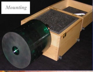
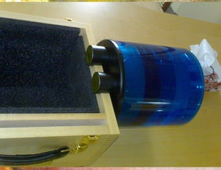
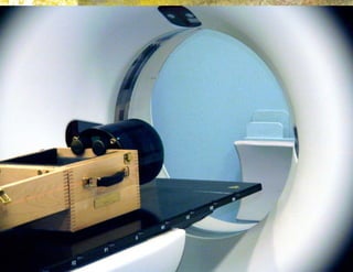
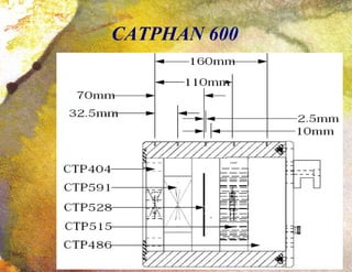
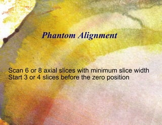
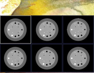
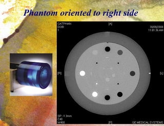
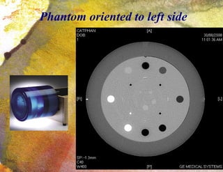
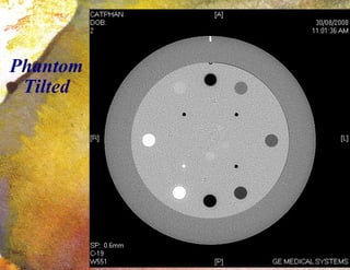
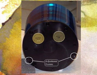
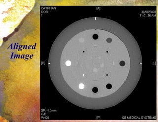
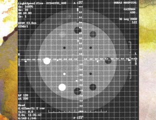
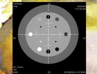
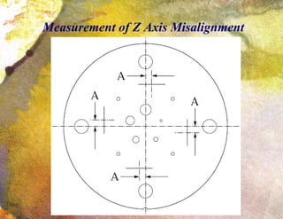
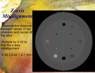
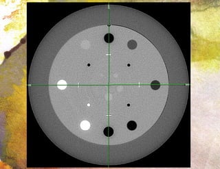
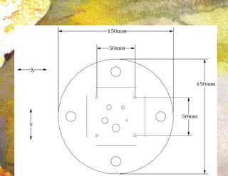
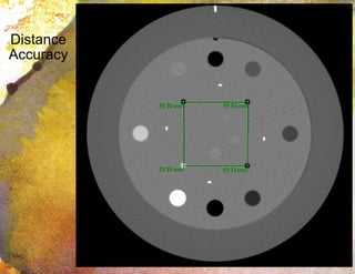
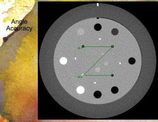
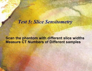
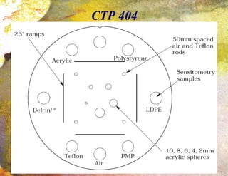
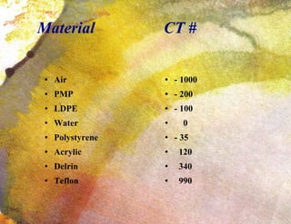
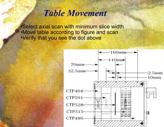
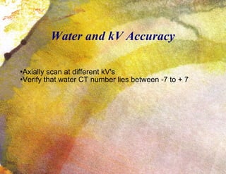
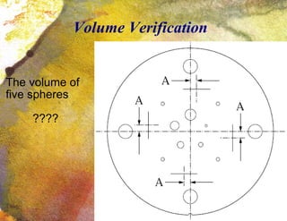
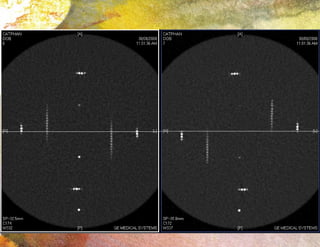
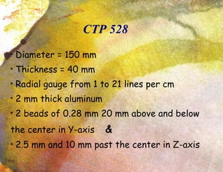
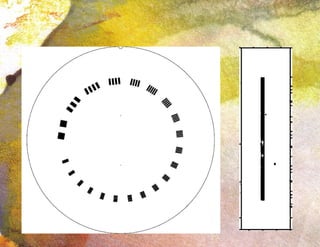
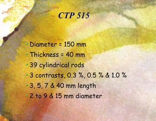
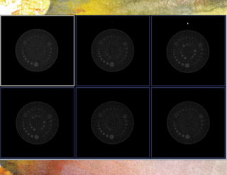
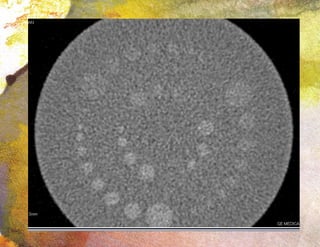
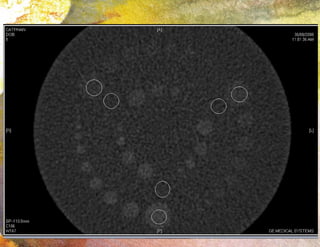
The document discusses performance testing of a computer tomography (CT) scanner using various modules of the CATPHAN phantom. It provides instructions on how to use the different modules to test: [1] laser alignment accuracy, slice thickness accuracy, low contrast detectability, and uniformity; [2] patient alignment system accuracy and circular symmetry; [3] sensitometry and effects of changing kV. Proper phantom positioning and avoiding manual movement are emphasized to obtain reliable results.
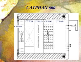


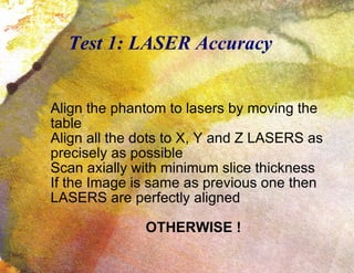


![ONFH[AVN HIP] -TRIPLE REGIME -A NOVAL SURGICAL CONCEPT .pptx](https://cdn.slidesharecdn.com/ss_thumbnails/onfhavnhip2026koaconcalicutdrgokuldevdrmashraf-260210064517-213ec005-thumbnail.jpg?width=640&height=640&fit=bounds)


