Download to read offline

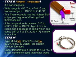
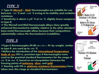
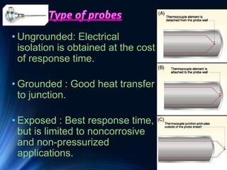

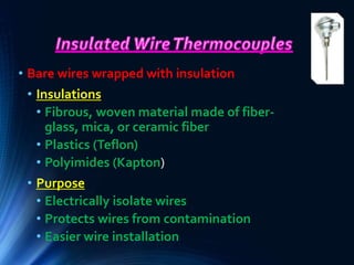
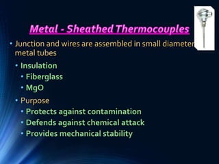
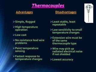

The document discusses thermocouples, which are devices that measure temperature based on the principle that a voltage is generated at the junction of two dissimilar metals when exposed to different temperatures. It outlines the types of thermocouples (such as types K, J, E, N, M, and S) based on their metal compositions and temperature ranges, as well as the governing principles like the Seebeck, Peltier, and Thomson effects. Additionally, it highlights construction types, applications, advantages, and disadvantages of thermocouples.


