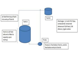
The document discusses how to calculate total dynamic head (TDH) in an industrial pumping system. TDH is comprised of vertical rise and friction loss. It is important to accurately calculate TDH to properly size pumping equipment. To calculate TDH:
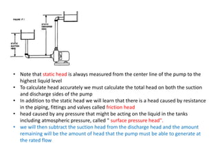
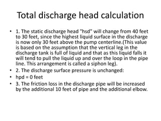
1) Determine the vertical rise between the liquid's starting and ending points, assuming an empty tank for the worst case.
2) Calculate friction losses of all pipe and components the liquid encounters on discharge.
3) Add the vertical rise and friction losses together to obtain the total dynamic head. An example calculation is provided to demonstrate determining TDH for 25 GPM flowing from a pump to Tank B.


![Head Calculations
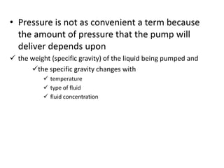
• Capacity is measured in gal/min. (Volumetric
flow rate)
• we can easily calculate the lb/min being
pumped. (mass flow rate) [ How?]
• Head or height is measured in feet
• If we multiply these two together we get:
ft-Ib/min which converts directly to work as
33,000 ft-Ib/min = 1 hp](https://image.slidesharecdn.com/3-240316115212-ae3b309a/85/3-Pump-Design-v-Pump-Design-vvvvvv-pptx-2-320.jpg)