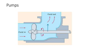
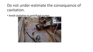
Pumps
Pumps: Energy required
Energy is required to lift weights
Pumps: Introduction
(the pump moves fluid)
• Pumps operate and consume energy to perform
mechanical work moving the fluid.
• Pumps operate via many energy sources, including
manual operation, electricity, engines, or wind power.
Work done by the pump is found by
setting energy balance equation
Energy required for pumping liquid/gases depends on:
1. Height through which the fluid is raised.
2. The pressure required @ delivery point.
3. The length & diameter of the pipe
4. The flow rate
5. Physical properties of the fluid, e.g viscosity &
density
Static Suction Lift
• Suction head: Show static heads in a pumping system where
the pump is located above the suction tank.
• SUCTION HEAD (or static suction lift) exists when the
source of supply is below the center line of the pump.
Static Suction Lift
Suction head
SUCTION HEAD exists when the source of supply is above the centerline of the pump. Thus the
STATIC SUCTION HEAD is the vertical distance from the centerline of the pump to the free level of
the liquid to be pumped.
Head section
STATIC DISCHARGE HEAD is the vertical distance
between the pump centerline and the level of the
liquid in the discharge tank.
TOTAL STATIC HEAD is the vertical distance between the
free level of the liquid in the inlet tank and the level of
the liquid in the discharge tank.
FRICTION HEAD (hf) is the head required to overcome
friction as fluid flows in the pipe and fittings. It depends
on the size, condition and type of pipe, the number and
type of pipe fittings, the flow rate and the nature of the
liquid.
Examples of pipe fittings
Head section
• VELOCITY HEAD (hv) is the energy of the fluid. It is the height that a
liquid must reach to reach a given velocity.
or in other words, the head necessary to accelerate the liquid.
Velocity head can be calculated.
• The velocity head is usually insignificant and can be ignored in most
high head systems. However, it can be a large factor and must be
considered in low head systems.
Head section
• PRESSURE HEAD must be considered when a pumping system begins
or ends in a tank that is under a pressure that is different from
atmospheric pressure.
• The above forms of head, namely static, friction, velocity, and
pressure, are combined to form the total system head for a given flow
rate.
Head section
• TOTAL DYNAMIC SUCTION LIFT (hs) is the sum of:
- Static suction lift or head
- Friction head in the suction pipe
• TOTAL DYNAMIC DISCHARGE HEAD (hd) is the static discharge head
plus the friction head in the discharge pipe.
Head section
• TOTAL HEAD (H) or TOTAL Dynamic HEAD (TDH) is the total dynamic
discharge head plus or minus the total dynamic suction head or
• TDH = hd + hs (with a suction lift)
• TDH = hd - hs (with a suction head)
• TDH is the work the pump must do in order to lift the water to the
desired height.
The characteristic curves of centrifugal pumps plot
the following parameters against the flow rate (Q):
- The head (H) (see H/Q curve),
- The power input (P),
- The pump efficiency (η)
- The NPSHr, i.e. the NPSH required by the pump.
Pump Performance Curve
Four curves:
1. Head Vs flow curve (H-Q
Curve)
2. Efficiency curve
3. Power or Energy curve
4. NPSH required curve
Pump Performance Curve
From the above Figure
Head Vs flow curve (H-Q Curve): From point A to point B, the head
will be decreased with an increase in the flow rate.
Efficiency curve: initially the pump efficiency will increase and reach a
maximum and then decreasing with increasing flow rate. Point C
(maximum efficiency) is called BEP (best efficiency point).
Normally, you should operate the pump within 10% range from BEP
to avoid damage the pump impeller and seal.
When you select the pump, you have to choose the head and flow
rate within this range.
Power or Energy curve: with the increase in head and flow rate, the
power consumption will also increase (this means when the pump
has to do more work, it needs more power).
NPSH required curve : Net positive suction head at the pump suction
is necessary to prevent cavitation in pump. The NPSH requirement
will increase with increasing the flow rate (This is like more liquid with
a higher head has to enter the pump when you push more liquid out).
Pump Performance Curve
This chart is used to select a
pump.
The pump speed is constant
and the diameter is fixed.
• Example: You want a pump with 30 meters head and 16 L/s flow rate. You want your pump
to run with best efficiency to save running and maintenance cost.
Pump Performance Curve
If you select an impeller wit a diameter of
around 145 mm and 5 kW motor will
achieve your requirements.
Pump Performance Curve
• Increasing the impeller diameter or speed increases the head, flow
rate capacity and and power consumption.
• The head capacity or the flow rate capacity can be increased by
connecting two or more pumps in parallel.
Pump suction performance (NPSH)
What is cavitation of pump?
Cavitation occurs when the liquid in a pump turns to a vapour at low pressure. It occurs
because there is not enough pressure at the suction side of the pump, or insufficient Net
Positive Suction Head available (NPSH). When cavitation happens, vapour cavites or
bubbles appear along the impeller vanes just behind the inlet edges.
Pump suction performance (NPSH)
Cavitation has three undesirable effects:
1) The cavitation bubbles can corrode the vane surface, especially
when pumping water-based liquids.
Pump suction performance (NPSH)
• 2) Noise and vibration are increased.
• 3) Reduction of the pump performance.
Pump suction performance (NPSH)
• NPSH (Net Positive Suction Head) is a minimum pressure head that
we need to prevent cavitation on the suction side of a centrifugal
pump
Do not under-estimate the consequence of
cavitation.
• Avoid cavitation in centrifugal pumps.
How to prevent cavitation due to vaporization
Required NPSHr
Or
1. Lower the temperature.
2. Raise the liquid level in the suction vessel.
3. Change the pump.
4. Reduce motor rpm if possible.
5. Increase the diameter of the eye of the impeller.
6. Use an impeller inducer.
7. Use two lower capacity pumps in parallel.
8. Use a booster pump to feed the principal pump.

Pumps Part 2 students(1) (3).pptx

  • 1.
  • 2.
    Pumps: Energy required Energyis required to lift weights
  • 3.
    Pumps: Introduction (the pumpmoves fluid) • Pumps operate and consume energy to perform mechanical work moving the fluid. • Pumps operate via many energy sources, including manual operation, electricity, engines, or wind power.
  • 4.
    Work done bythe pump is found by setting energy balance equation Energy required for pumping liquid/gases depends on: 1. Height through which the fluid is raised. 2. The pressure required @ delivery point. 3. The length & diameter of the pipe 4. The flow rate 5. Physical properties of the fluid, e.g viscosity & density
  • 5.
    Static Suction Lift •Suction head: Show static heads in a pumping system where the pump is located above the suction tank.
  • 6.
    • SUCTION HEAD(or static suction lift) exists when the source of supply is below the center line of the pump. Static Suction Lift
  • 7.
    Suction head SUCTION HEADexists when the source of supply is above the centerline of the pump. Thus the STATIC SUCTION HEAD is the vertical distance from the centerline of the pump to the free level of the liquid to be pumped.
  • 8.
    Head section STATIC DISCHARGEHEAD is the vertical distance between the pump centerline and the level of the liquid in the discharge tank. TOTAL STATIC HEAD is the vertical distance between the free level of the liquid in the inlet tank and the level of the liquid in the discharge tank. FRICTION HEAD (hf) is the head required to overcome friction as fluid flows in the pipe and fittings. It depends on the size, condition and type of pipe, the number and type of pipe fittings, the flow rate and the nature of the liquid.
  • 9.
  • 10.
    Head section • VELOCITYHEAD (hv) is the energy of the fluid. It is the height that a liquid must reach to reach a given velocity. or in other words, the head necessary to accelerate the liquid. Velocity head can be calculated. • The velocity head is usually insignificant and can be ignored in most high head systems. However, it can be a large factor and must be considered in low head systems.
  • 11.
    Head section • PRESSUREHEAD must be considered when a pumping system begins or ends in a tank that is under a pressure that is different from atmospheric pressure. • The above forms of head, namely static, friction, velocity, and pressure, are combined to form the total system head for a given flow rate.
  • 12.
    Head section • TOTALDYNAMIC SUCTION LIFT (hs) is the sum of: - Static suction lift or head - Friction head in the suction pipe • TOTAL DYNAMIC DISCHARGE HEAD (hd) is the static discharge head plus the friction head in the discharge pipe.
  • 13.
    Head section • TOTALHEAD (H) or TOTAL Dynamic HEAD (TDH) is the total dynamic discharge head plus or minus the total dynamic suction head or • TDH = hd + hs (with a suction lift) • TDH = hd - hs (with a suction head) • TDH is the work the pump must do in order to lift the water to the desired height.
  • 14.
    The characteristic curvesof centrifugal pumps plot the following parameters against the flow rate (Q): - The head (H) (see H/Q curve), - The power input (P), - The pump efficiency (η) - The NPSHr, i.e. the NPSH required by the pump. Pump Performance Curve
  • 15.
    Pump Performance Curve Fourcurves: 1. Head Vs flow curve (H-Q Curve) 2. Efficiency curve 3. Power or Energy curve 4. NPSH required curve
  • 16.
    Pump Performance Curve Fromthe above Figure Head Vs flow curve (H-Q Curve): From point A to point B, the head will be decreased with an increase in the flow rate. Efficiency curve: initially the pump efficiency will increase and reach a maximum and then decreasing with increasing flow rate. Point C (maximum efficiency) is called BEP (best efficiency point). Normally, you should operate the pump within 10% range from BEP to avoid damage the pump impeller and seal. When you select the pump, you have to choose the head and flow rate within this range.
  • 17.
    Power or Energycurve: with the increase in head and flow rate, the power consumption will also increase (this means when the pump has to do more work, it needs more power). NPSH required curve : Net positive suction head at the pump suction is necessary to prevent cavitation in pump. The NPSH requirement will increase with increasing the flow rate (This is like more liquid with a higher head has to enter the pump when you push more liquid out). Pump Performance Curve
  • 18.
    Pump Performance Curve Thischart is used to select a pump. The pump speed is constant and the diameter is fixed.
  • 19.
    • Example: Youwant a pump with 30 meters head and 16 L/s flow rate. You want your pump to run with best efficiency to save running and maintenance cost. Pump Performance Curve If you select an impeller wit a diameter of around 145 mm and 5 kW motor will achieve your requirements.
  • 20.
    Pump Performance Curve •Increasing the impeller diameter or speed increases the head, flow rate capacity and and power consumption. • The head capacity or the flow rate capacity can be increased by connecting two or more pumps in parallel.
  • 21.
    Pump suction performance(NPSH) What is cavitation of pump? Cavitation occurs when the liquid in a pump turns to a vapour at low pressure. It occurs because there is not enough pressure at the suction side of the pump, or insufficient Net Positive Suction Head available (NPSH). When cavitation happens, vapour cavites or bubbles appear along the impeller vanes just behind the inlet edges.
  • 22.
    Pump suction performance(NPSH) Cavitation has three undesirable effects: 1) The cavitation bubbles can corrode the vane surface, especially when pumping water-based liquids.
  • 23.
    Pump suction performance(NPSH) • 2) Noise and vibration are increased. • 3) Reduction of the pump performance.
  • 24.
    Pump suction performance(NPSH) • NPSH (Net Positive Suction Head) is a minimum pressure head that we need to prevent cavitation on the suction side of a centrifugal pump
  • 25.
    Do not under-estimatethe consequence of cavitation. • Avoid cavitation in centrifugal pumps.
  • 26.
    How to preventcavitation due to vaporization Required NPSHr Or 1. Lower the temperature. 2. Raise the liquid level in the suction vessel. 3. Change the pump. 4. Reduce motor rpm if possible. 5. Increase the diameter of the eye of the impeller. 6. Use an impeller inducer. 7. Use two lower capacity pumps in parallel. 8. Use a booster pump to feed the principal pump.