
Recommended
More Related Content
What's hot
What's hot (20)
Similar to 1 s2.0-s0038092 x18311939-main
Similar to 1 s2.0-s0038092 x18311939-main (20)
Recently uploaded
Recently uploaded (20)
1 s2.0-s0038092 x18311939-main
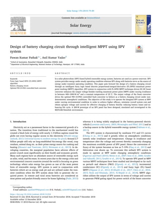
- 1. Contents lists available at ScienceDirect Solar Energy journal homepage: www.elsevier.com/locate/solener Design of battery charging circuit through intelligent MPPT using SPV system Pawan Kumar Pathaka,⁎ , Anil Kumar Yadavb a School of Automation, Banasthali Vidyapith, Rajasthan 304022, India b Department of Electrical Engineering, National Institute of Technology, Hamirpur, HP 177005, India A R T I C L E I N F O Keywords: Fuzzy logic based DPID (FL-DPID) MPPT algorithm Battery charging circuit Optimal PID (O-PID) controlled buck converter A B S T R A C T In a solar photovoltaic (SPV) based hybrid renewable energy system, batteries are used as a power reservoir. SPV system provides energy under steady operating condition whereas SPV along with batteries serve as the source of energy under transient operating condition. This paper puts forward the design of a battery charging circuit through an intelligent fuzzy logic based discrete proportional-integral-derivative (FL-DPID) maximum power point tracking (MPPT) algorithm. SPV system in conjunction with FL-DPID MPPT technique driven DC-DC boost converter enhances the output voltage besides tracking maximum power point (MPP) under varying irradiance in between 400–1000 W/m2 and a constant temperature of 25 °C. The output voltage of the boost converter drives the optimal PID (O-PID) controlled buck converter to behave as a battery charging circuit under non- deterministic atmospheric conditions. The objective of this study is to operate the designed SPV system at MPP under varying environmental condition in order to achieve higher efficacy, minimize overall system cost and obtain apropos voltage and current for effective charging of battery thereby reducing battery losses and en- hancing life cycle. A 200 W prototype of an SPV panel has been designed, simulated and investigated in the MATLAB/Simulink environment. 1. Introduction Electricity act as a paramount factor in the commercial growth of a nation. The transition from traditional to the mechanized world has created a black hole of energy with nearly 1.3 billion sapiens round the globe not even having regular access to the electricity (World energy outlook, 2013; Universal access to modern energy for poor). Around 2.7 billion people still rely on long-established bio-energy like wood, crop residues, animal dung etc. as their prime energy source for cooking and heating (Ekouevi and Tuntivate, 2012; Weimann et al., 2013). In de- veloping countries, the marginal population faces adverse effects of power crunch most significantly on their health and economic growth. Many such regions have an abundant source of renewable energy such as solar, wind, and bio-mass. In recent years due to the energy crisis and environmental concern countries around the world is focusing on green technology where solar energy has grown as one of the most potent form of renewable energy. SPV system is used in conjunction with batteries which act as energy soak pit and are utilized under the tran- sient condition when the SPV system alone fails to generate the re- quired power. In remote and rural areas batteries are considered as most potent and pocket-friendly source for home lightning (Pode, 2015) whereas it is being widely employed in the battery-powered electric vehicle (Larminie and Lowry, 2003; Wirasingha and Pihef, 2011) and as a backup source in the hybrid renewable energy system (Fakham et al., 2011). The SPV system is characterized by nonlinear P-V and I-V curves (Cheng et al., 2015) and it greatly relies on atmospheric conditions namely solar irradiance and temperature. Change in irradiance and temperature alter the voltage and current thereby constantly changing the maximum available power of SPV panel. Hence the conversion ef- ficacy of the system becomes as low as 7–19% (Haq et al., 2013) and fabrication cost shoots up. To overcome this setback SPV system is made to operate at MPP under changing atmospheric conditions (Agarwal and Patel (2010); Metin et al., 2007; Soto et al., 2006; Graditi and Adinolfi, 2011; Graditi et al., 2014). To operate SPV panel at MPP various MPPT techniques have been studied and developed so far such as perturb and observe (P&O) (Elgendy et al., 2012), incremental conductance (IC) (Elgendy et al., 2013) and fuzzy logic (FL) based MPPT (Algazar et al., 2012; EI-Khatib et al., 2017; Chen et al., 2016, 2015; Rezk and Eltamaly, 2015; Al-Majidi et al., 2018). MPPT algo- rithm utilizes the output of SPV system in terms of voltage and current to generate PWM gating signal for power switch of the boost converter https://doi.org/10.1016/j.solener.2018.12.018 Received 15 July 2018; Received in revised form 29 November 2018; Accepted 7 December 2018 ⁎ Corresponding author. E-mail addresses: ppathak999@gmail.com (P.K. Pathak), anilei007@gmail.com (A.K. Yadav). Solar Energy 178 (2019) 79–89 Available online 12 December 2018 0038-092X/ © 2018 Elsevier Ltd. All rights reserved. T
- 2. to modulate its output (Fathabadi, 2016; Singh et al., 2018; Babaei et al., 2017; Hart, 2011; Adinolfi et al., 2015; Graditi et al., 2010). Constant voltage and constant currents are the mostly used methods to charge a battery (Borage et al., 2006; Cho et al., 2013; Chen and Lai, 2012). To render invariable current and voltage to the connected load PID controlled buck converter is employed as the charging circuit. The PID controller is widely used in various industrial applications such as electric vehicles, process control, and power system because of its in- expensiveness, ease in designing and excellent performance (Yadav and Gaur, 2016a,b; Ang et al., 2005; Neath et al., 2014). Yilmaz et al. (2018) proposed FL based SPV system for battery charging circuit under different atmospheric conditions and analyzed the system response. Eldahab et al. (2016) develop a novel MPPT technique for SPV based battery charging controller. The prominent feature of this novel MPPT technique is remote monitoring and controlling of various system ele- ments. Mirzaei et al. (2017) designed a control topology for power management in a standalone hybrid system. Pode (2015) details battery charging stations which are quite welcomed in lonesome which are yet not connected to the grid. The implementation of digital control strategy through DSP has been done by Lopez et al. (2016) for buck converter charging a battery through solar generated power under various atmospheric conditions. In Rajani and Pandya et al. (2016) MPPT based SPV system is utilized for charging battery and ultra-ca- pacitor individually, and it depicts the enhancement in the charging rate as compared to non MPPT charging. The structure of FL-DPID MPPT technique is proposed and im- plemented for battery charging circuit under varying solar irradiance in between 400–1000 W/m2 . The proposed MPPT technique has been designed with a lesser number of rules i.e. nine as compared to existing literature (Yilmaz et al., 2018). An FL based system with the least number of rules reduces the computational time and complexity of the system. The output voltage of FL-DPID MPPT driven boost converter having least ripple drives the O-PID controlled buck converter to deliver regulated power to the battery as a load with constant voltage and constant current irrespective of change in solar irradiance as shown in Fig. 1. The parameters of the proposed O-PID controller are obtained utilizing a Genetic Algorithm (GA) with suitable objective function. The results of O-PID controlled buck converter are compared with Ziegle- r–Nichols (ZN) tuned PI and PID controllers and named as ZN-PI and ZN-PID respectively. The expected advantages of O-PID controller over ZN-PI and ZN-PID controllers are to improve the performances indices such as rise time (RT), settling time (ST), overshoot (OS), integral of the absolute error (IAE) and integral of the square of error (ISE) that re- duces the charging time of the battery thereby enhancing its life. The key contributions of the paper are summarized as follows: (1) The de- sign and implementation of intelligent i.e. FL-DPID MPPPT technique for battery charging circuit under varying solar irradiance i.e. 400–1000 W/m2 and the results are compared with existing P&O and IC MPPT techniques. (2) A detailed comparative analysis among designed ZN-PI, ZN-PID and O-PID controllers of buck converter for charging of a 18 V battery. The results are compared with the literature (Yilmaz et al., 2018). The transient response and ripples in output voltage and current of the boost converter are considered as the key factors for a compre- hensive comparison of designed P&O, IC, and FL-DPID MPPT techni- ques. The rest of the work is organized as follows. Section 2 deals with design considerations of one diode model of a crystalline solar cell and SPV module along with its characteristics under varying atmospheric condition. In Section 3 the design methodology of P&O, IC, and FL- DPID MPPT techniques are presented. The design of DC-DC power converter covers the power conversion system including both DC-DC boost and buck converter employing control strategies such as ZN-PI, ZN-PID, and O-PID controllers are discussed in section 4. The obtained results have been vividly discussed in Section 5 i.e. results and dis- cussion, and the concluding remarks of this research are presented in Section 6. 2. Description of SPV system The output and efficacy of the SPV system completely rely on dif- ferent array configuration as well as various atmospheric conditions such as non-uniform solar insolation and varying the environmental temperature. The P-V and I-V characteristics of an SPV system for a constant environmental temperature of 25 °C and varying solar insola- tion have been depicted in Fig. 2(a) and (b), whilst Fig. 3(a) and (b) represents the P-V and I-V characteristics of an SPV subjected to varying temperature keeping insolation constant at 1000 W/m2 respectively. The effect of a change in temperature as seen from Figs. 2 and 3 has a lesser influence on the characteristic of the SPV system as compared to the change in solar insolation. Therefore, in this paper, the work is Optimal PID Controller Battery Ipv Vpv D Boost Converter Buck Converter PWM Generator 1 FL-DPID MPPT Vpv Vdc Vdcb PWM Generator 2 D PV Array Ref. Value Actual Value U u e + - Ipv Fig. 1. SPV system based battery charging circuit. P.K. Pathak, A.K. Yadav Solar Energy 178 (2019) 79–89 80
- 3. focused on constant solar temperature i.e. 25 °C and varying solar in- solation in range of 400–1000 W/m2 for the SPV system based battery charging circuit. 2.1. Mathematical equation of a solar cell The simplified electrical circuit of each solar cell can be modeled in various ways out of which one diode model is considered in the pre- sented work. A simplified circuit for the same is represented in the Fig. 4 and the I–V relation is given below: = − − − + + { } I I I e V R I R 1 ph s sh 0 q V RsI AKT ( ) (1) where Iph denotes photocurrent, Id is the current through diode, I the sh denotes shunt current, Rsh denotes shunt resistance, Rs denotes series connected resistance, I denotes the net output current of SPV, V de- notes the voltage across SPV, I0 denotes diode reverse saturation cur- rent, q denotes charge of the electron, A is curve fitting factor andKis the Boltzmann constant (1.38 × 10⁻²³ J/K). 2.2. Modeling of an SPV module The last term of (1) can be omitted due to Rsh is assumed to be infinite and the slope of I-V curve is zero at short circuit condition. Further replacing Iph by ISC (short-circuit current): = − − + { } I I I e 1 SC O q V RsI AKT ( ) (2) In a PV module the appropriate application of (2) + q V R I AKT ( ) s is mod- ified and substituted by + q V R I N AKT ( ) s s , where Ns denotes total solar cells connected back to back in a crystalline type SPV module. Yields (3); = − − + { } I I I e 1 SC O q V RsI NsAKT ( ) (3) Under the open-circuit condition of a PV module, = I 0 and hence the term q N AKT s in (3) will be written as follows: = + ( ) q N AKT V ln 1 s I I OC SC O (4) where VOC denotes module open-circuit voltage. The current can be obtained from (3) and (4) as: ⎜ ⎟ = ⎧ ⎨ ⎩ − ⎛ ⎝ − ⎞ ⎠ ⎫ ⎬ ⎭ ⎛ ⎝ + ⎞ ⎠ + I I I I e 1 1 SC O SC I I V R I V ln 1 ( ) SC O S OC (5) where = k I I / SC O and after solving (5), obtained (6): = ⎧ ⎨ ⎩ − + + ⎫ ⎬ ⎭ + I I k k k 1 1 ( 1) 1 SC V RSI VOC ( ) (6) (a) (b) 0 5 10 15 20 25 30 34 50 100 150 200 Voltage (V) Power (W) 1000 W/m2 800 W/m2 600 W/m2 400 W/m2 0 5 10 15 20 25 30 34 1 2 3 4 5 6 7 8 9 Voltage (V) Current (A) 1000 W/m2 800 W/m2 600 W/m2 400 W/m2 Fig. 2. (a) P-V curve and (b) I-V curve on different solar irradiance. (b) (a) 0 5 10 15 20 25 30 34 50 100 150 200 Voltage (V) Power (W) 25 degC 50 degC 75 degC 0 5 10 15 20 25 30 34 0 2 4 6 8 9 Voltage (V) Current (A) 25 degC 50 degC 75 degC Fig. 3. (a) P-V curve and (b) I-V curve on different temperature. Rs Rsh I V Iph Ish Id D Fig. 4. Equivalent circuit of a solar cell. P.K. Pathak, A.K. Yadav Solar Energy 178 (2019) 79–89 81
- 4. Usually, kis quite high as ISC is much greater than IO. Few terms in (6) can be ignored for simplified I–V relation which is represented as follows: ⎜ ⎟ = ⎛ ⎝ − ⎞ ⎠ + − I I k 1 SC V R I V ( ) 1 S OC (7) 3. Maximum power point tracking (MPPT) techniques The major setback of a commercial SPV system is less conversion efficiency. Therefore, to enhance the efficacy of the system MPPT al- gorithm is employed. The maximum efficiency is expected from an SPV system when it operates at MPP and as represented in Fig. 5. 3.1. Perturb & observe (P&O) P&O is based on perturbation in array voltage. From the P-V curve of an SPV array as shown in Fig. 6 it can be observed that while op- erating on the left side of MPP increasing/decreasing with increasing/ decreasing the voltage ΔV, whereas it decreases/increases on the right of MPP. For minimizing the oscillations, the step size of perturbation can be reduced. The entire P&O algorithm is depicted as follows: P&O algorithm: Step 1: Start Step 2: Read variables V n ( )andI n ( ). P&O algorithm: Step 3: Calculate power: = ∗ P n V n I n ( ) ( ) ( ). Step 4: Call previous values of P and V from the memory i.e. − P n ( 1) and − V n ( 1). Step 5: Calculate the change in power ‘dP’ and change in voltage‘dV ’ using: = − − dV V n V n ( ) ( 1) and = − − dP P n P n ( ) ( 1). Step 6: If = dP 0, Then no change in duty ratio is required and GOTO Step 7. else If ∗ > dP dV ( ) 0, Then increase the duty ratio by ΔD and GOTO Step 7. else decrease the duty ratio by ΔD and GOTO Step 7. Step 7: Return. 3.2. Incremental conductance (IC) The P&O technique fails under rapidly changing environmental conditions; this can be overcome by using the IC technique. The slope of the P-V curve of an SPV array is the basis of the IC algorithm. The derivative of the output power of the SPV array is written as follows: = = + = + dP dV d IV dV I V dI dV I V I V ( ) Δ Δ (8) The entire IC algorithm is depicted as follows: IC algorithm: Step 1: Start Step 2: Read variables V n ( ) andI n ( ). Step 3: Call previous values of I and V from the memory i.e. − I n ( 1) and − V n ( 1). Step 4: Calculate the change in current‘dI’ and change in voltage‘dV ’ using: = − − dV V n V n ( ) ( 1) and = − − dI I n I n ( ) ( 1). Step 5: If = dV 0, Then GOTO Step 6. else GOTO Step 7. Step 6: If = dI 0, Then GOTO Step 8 else If > dI 0, Then increase duty ratio by ΔD and GOTO Step 8. else decrease the duty ratio by ΔD and GOTO Step 8. Step 7: If + < ε dI dV I V , Then GOTO Step 8. else If > − dI dV I V , Then increase duty ratio by ΔD and GOTO Step 8. else decrease the duty ratio by ΔD and GOTO Step 8. Step 8: Update V n ( ) andI n ( ). Step 9: Return. 3.3. FL-DPID MPPT technique The proposed FL-DPID is a powerful MPPT algorithm to operate at MPP for SPV system. The advantages of FL-DPID MPPT over P&O and IC MPPTs are a minimum ripples in the output, the capability to handle nonlinearity, work with inexplicit inputs, and non-requirement of the exact mathematical model whereas when compared to FL based MPPT it reduces implementation and computation complexity. The flowchart and proposed structure of FL-DPID MPPT technique are depicted in Fig. 7(a) and (b) respectively. The symbols K K K , , e ce p and Ki are the scaling factors of FL-DPID MPPT controller and are obtained based on intuition through ZN tuning method (Yadav and Gaur, 2016b). The error E and change in error CE acts as the input variables of FL- DPID MPPT and are computed using the output power and voltage of SPV system as represented by (9) and (10). = = − − − − E n P V P n P n V n V n ( ) Δ Δ ( ) ( 1) ( ) ( 1) (9) = − − CE n E n E n ( ) ( ) ( 1) (10) The output variable of the FL system is UPD and the accumulated output of FL-DPID MPPT is UPID as shown in Fig. 7(b). The UPID i.e. U is acts as a reference and provided as an input to PWM genrator−1 that modifies the duty cycle D as shown in Fig. 1. From Fig. 7(b), the control law of FL-DPID MPPT i.e. UPID is written as follows: = + − − U K U K Z U · · 1 1 · PID p PD i PD 1 (11) The relation between input variable E and output variable UPD of product-sum crisp type fuzzy is approximated and described as follows (Yadav and Gaur, 2016a,b): PMPP Power Maximum Power Point (MPP) Current ISC IMP Current (A) 0 0 Voltage (V) VMPP VOC Fig. 5. P-V and I-V curve for MPP. Fig. 6. P-V curve of an SPV array. P.K. Pathak, A.K. Yadav Solar Energy 178 (2019) 79–89 82
- 5. = + − − U K E K Z E · ·(1 )· PD e ce 1 (12) From (11) and (12) = + − + − + − − − − U K K E K Z E K Z K E K Z E [ · ·(1 )· ] 1 [ · ·(1 )· ] PID p e ce i e ce 1 1 1 (13) After solving (13), yields (14) ⏟ ⏟ ⏟ = + + × − + × − − − U K K K K E K K Z E K K Z E ( )· ( )· 1 1 · ( )·(1 )· PID p e ce i Proportionalgain e i Integralgain p ce Derivativegain 1 1 (14) The final control law (14) represents the generalized equation of three term PID controller in the discrete domain. Therefore, the pro- posed structure of FL based MPPT is named as FL-DPID MPPT tech- nique. The membership functions (MFs) forE and CE, and UPD are shown in Fig. 8(a), and (b) respectively. The linguistic names of these MFs are as follows: NB (Negative Big), N (Negative), Z (Zero), P (Po- sitive) and PB (Positive Big). Start Measure V (n) and I (n) Calculate P (n) = V (n)*I (n), dP and dV Initialize duty cycle (D) Calculate Error (E) & Change in error (CE) Defuzzification Inference Fuzzification Rule base Update D Fuzzy set (a) Ke Kce + - Z-1 Z-1 E + UPID Fuzzy Logic UPD + Kp Ki + + (b) Fig. 7. (a) Flowchart and (b) Proposed structure of FL-DPID MPPT technique. P.K. Pathak, A.K. Yadav Solar Energy 178 (2019) 79–89 83
- 6. The E and CE after being calculated and transmuted to the semantic variables depending on the MFs generates the output of FL-DPID con- troller in terms of UPID which in turn alter the duty cycle ΔD of the boost converter. The ΔD is deducted from previous value of D and the new value acts as the gating signal that controls the boost converter to track the MPP of the SPV system. The crisp output UPD can be obtained from the rule base matrix as given in Table 1. The 9 rules of Table 1 can be expressed as follows: Rule 6: ‘IF E is N and CE is Z THEN UPD is N’. Similarly, the other rules are described and used for evaluation of final output of FL-DPID controller (14) and ap- propriate ΔD is obtained. 4. Design of DC-DC power converters For maximized power output SPV is made to operate at MPP. To trace the MPP of SPV the power converter is operated with the corre- sponding D. With the change in solar insolation the D must vary ac- cordingly in order to track MPP. Various configuration of the DC-DC converter studied so far out of which boost converter is widely chosen and considered in the presented work due to less complexity and higher reliability as shown in Fig. 1. 4.1. DC-DC boost converter Metal-oxide-semiconductor field-effect transistor (MOSFET) is em- ployed as a switching device for the operation of the boost converter. During time period < < t DT 0 , MOSFET turns on and diode enters into reverse biased condition. During this time interval inductor L gets charged with the voltage = V V L in. During time period < < Dt t T, the MOSFET goes into off state and the diode is in on state due to forward biased. In this condition the output voltage = = + V V V V out dc in L. In steady state condition the total energy stored by, L must be equal to the energy released by L in a period of switching. The values of boost converter parameters L and C are calculated using formulas as follows: (Hart, 2011) = = − V V V D (1 ) out dc in (15) = − I D I (1 ) out in (16) = ∗ ∗ L V D f I Δ in s (17) = ∗ ∗ C I D f V Δ out s (18) where C is caapacitor, Iout is the current output of boost converter, I Δ denotes ripple in inductor current, V Δ denotes ripple in output voltage, fs denotes switching frequency of the power device and Iin is the input current of boost converter. 4.2. DC-DC buck converter Buck converter has the property of generating an output voltage which is lower in magnitude than the input supply. During < < t DT 0 , the MOSFET turns on whereas diode is in off state and charging in- ductor with a voltage = − V V V L dc dcb. MOSFET turns off during < < DT t T, diode comes in conduction with voltage developed across the inductor changing to = − V V L dcb. To render invariable current and voltage for charging a battery ZN-PI, ZN-PID and O-PID controllers are designed to generate a controlled reference signal u for PWM generator- 2 that gives the updated D to the buck converter as shown in Fig. 1. The parameters of DC-DC buck converter L and C are calculated using formulas as given follows: (Hart, 2011) = ∗ V D V dcb dc (19) -0.1 -0.05 0 0.05 N Z P 0 0.5 1 0.1 (a) 0 1 6 6 . 0 - 3 3 . 0 - 1 - 0.33 0.66 NB N Z P PB 0 0.5 1 (b) Fig. 8. MFs for (a) E and CE, and (b)UPD Table 1 Rule base matrix. E CE P Z N P PB (1) P (4) Z (7) Z P (2) Z (5) N (8) N Z (3) N (6) NB (9) P.K. Pathak, A.K. Yadav Solar Energy 178 (2019) 79–89 84
- 7. = ∗ − ∗ L V D f I (1 ) Δ dcb s b (20) = ∗ − ∗ ∗ ∗ C V D L f V (1 ) 8 Δ dcb s dcb (21) where Vdcb is the output voltage generated by the buck converter, Vdc denotes input dc supply voltage of the buck converter, I Δ b denotes ripple in inductor current and V Δ dcb is the ripple in output voltage. 4.3. Control strategy In this section, the design methodology of classical ZN-PI and ZN- PID controllers, and proposed O-PID controller for voltage regulation using buck converter is presented. The differential equation of a gen- eralized PID controller is usually represented in ‘parallel form’ or ‘ideal form’ stated by (22) or (23) respectively. ∫ = + + u t K e t K e t dt K e t ( ) ( ) ( ) ̇( ) P I D (22) ∫ = ⎡ ⎣ ⎢ + + ⎤ ⎦ ⎥ u t K e t T e t dt T e t ( ) ( ) 1 ( ) ̇( ) P I D (23) where K K K , and P I D denotes proportional, integral and derivative gains respectively, TI and TD denotes integral and derivative time constants respectively, and u and e are output and input i.e. error signal of the controller respectively. The performance parameters of the PID con- troller are quantified using ZN tuning method (Yadav and Gaur, 2016b); using relations as given below: For PI control: = = = K K T T K K T 0.75 , /1.2, / P u I u I P I (24) For PID control: = = = = = K K T T T T K K T K K T 0.6 , /2, /8, / and · P u I u D u I P I D P D (25) where Ku and Tu are the ultimate gain and period of the system re- spectively. Sometimes, the ZN tuned PI and PID controllers give un- desirable performance in terms of OS, RT, ST, IAE and ISE (Yadav and Gaur, 2016a; Neath et al., 2014). Therefore, the O-PID controller is proposed in this paper. In O-PID controller, the KP, KI, and KD are obtained using GA for which the objective function j is formulated using IAE and ISE, and given as follows: ∫ ∫ = + ∞ ∞ j w e t dt w e t dt · | ( )| · ( ) 1 0 2 0 2 (26) where w1 and w2 are weights to ∫ = ∞ IAE e t dt | ( )| 0 and ∫ = ∞ ISE e t dt ( ) 0 2 respectively, and equal weights for both IAE and ISE are considered in this paper. The objective is to find out the optimal values of KP, KI and KD which gives excellent performance in terms of OS, RT, ST, IAE and ISE. The initial generation of GA is arbitrary; therefore the PID controller parameters at the preliminary stage could introduce instability in the system. Hence the lower and upper limit of the controller parameters is chosen such that the system retains stability in this limit. The preliminary values of PID controller parameters are taken from ZN-PID controller that is given in Table 4. 5. Results and discussion The entire system represented schematically in Fig. 1 has been formulated and simulated using MATLAB/Simulink software. The nu- merical values used in the simulation are given in Table 2. The designed system consists of an SPV array for a peak power of 200 W, a DC-DC boost converter and a DC-DC buck converter acting as a charge con- troller for charging a 18 V battery and operating at a fs of 150 kHz. To operate the SPV system at MPP three distinct MPPT techniques are employed and a thorough comparative transient analysis of the dy- namic response of SPV system in terms of the output power of SPV corresponding to MPP and voltage and current of the boost converter under rapidly varying solar irradiation has been done. 5.1. Comparative analysis of P&O, IC, and FL-DPID MPPT techniques under varying solar irradiance The profile of solar radiation taken into account for the study has been illustrated in Fig. 9 i.e. varying in between 400–1000 W/m2 (Liu, et al., 2008). The change in solar irradiance for carrying out the de- tailed analysis has been considered as trapezoidal in nature divided into five states as 600 W/m2 at 25 °C, 800 W/m2 at 25 °C, 1000 W/m2 at 25 °C, 800 W/m2 at 25 °C, and 400 W/m2 at 25 °C. According to the considered solar irradiance profile state 2 and state 4 have been taken at same irradiance level, thus only state 2 has been considered for the analysis. The output parameters of boost converter i.e. voltage and current and maximum obtainable SPV power implementing P&O, IC, and FL-DPID MPPTs have been depicted in Fig. 10(a)–(c) respectively. The values of scaling factors K K K , , e ce p and Ki of FL-DPID MPPT technique are 0.095, 0.007, 0.7 and 0.3 respectively. The output vol- tage corresponding to MPP of SPV system incorporating FL-DPID MPPT algorithm along with the voltage after being boosted by the DC-DC boost converter has been represented in Fig. 11. A vivid comparison of all the three MPPT techniques in terms of efficiency, dynamic perfor- mance like ST and the effect of ripples on the performance of boost converter are summarized in Table 3. From the obtained results as shown in Fig. 10(a)–(c) and the cal- culated values as given in Table 3 it can be noted that with the rapid variation in the solar insolation the designed SPV system is efficiently able to trace the MPP in all the considered states. It can be spotted from Fig. 10(c) that under steady state condition P&O technique gives higher ripple caused due to oscillation around MPP which is substantially re- duced in IC technique and almost negligible in FL-DPID MPPT algo- rithm. Higher ripple in the P&O algorithm reduces the average power output and thereby reduces the efficacy of the SPV system. The max- imum obtained efficacy under all the considered states of solar insola- tion is 97.00% for P&O, 98.60% for IC and 99.80% for FL-DPID MPPT technique. In terms of dynamic response, FL-DPID MPPT strategy shows better performance in comparison to P&O and IC techniques. From the Fig. 10(c) it can be observed that FL-DPID MPPT technique gives least ST of 20 ms for power whereas in P&O and IC have 110 ms and 340 ms respectively. Considerable ripple in power leads to high ripple in the output of the boost converter whose duty cycle ‘D’ in turn is decided by the implemented MPPT technique. The ripple content in the output voltage, as well as the current of the boost converter, is highest for P&O as shown in Fig. 10(a) and (b) with response remaining unsettled for the entire simulation time and FL-DPID MPPT technique has almost negli- gible ripple with ST of 23 ms for voltage as well as current. From the comparative analysis, FL-DPID MPPT algorithm surpasses P&O and IC algorithms in respect of steady state as well as dynamic response i.e. Table 2 Numerical values for simulation. System Symbols Values SPV VOC/module 10.908 V ISC/module 8.21 A Cells in a module 18 Ns 3 NP 1 A 1.36 Boost fs 150 kHz L 0.1075 mH C 10.41 µF Buck fs 150 kHz L 0.1613 mH C 1.744 µF P.K. Pathak, A.K. Yadav Solar Energy 178 (2019) 79–89 85
- 8. Time (sec.) Irradiance (W/m2) 0.0 0.4 0.9 1.4 1.9 600 800 1000 State 1 State 2 State 3 State 4 0.5 1 1.5 2 2.4 State 5 400 800 Fig. 9. Profile of solar irradiance. (a) (b) (c) 0 0.5 1 1.5 2 2.4 0 10 20 30 40 47 Time (sec.) Voltage (V) 1.05 1.051 1.052 1.053 24 35 P&O IC FL-DPID 0 0.5 1 1.5 2 2.4 0 1 2 3 4 5 6 7 Current (A) P&O IC FL-DPID 1.05 1.051 1.052 1.053 3.6 4.3 Time (sec.) 0 0.5 1 1.5 2 2.4 0 50 100 150 200 Time (sec.) Power (W) 1.05 1.07 1.09 1.1 190 202 1.05 1.07 1.09 1.1 190 202 1.06 1.08 1.1 198 200 P&O IC FL-DPID Fig. 10. (a) Output voltage, (b) Output current of boost converter and (c) Maximum power using P&O, IC and FL-DPID MPPT techniques. P.K. Pathak, A.K. Yadav Solar Energy 178 (2019) 79–89 86
- 9. efficiently tracking MPP under varying irradiance with least ST and bearing least ripple in output voltage and current of the boost con- verter. The output voltage of the boost converter as seen in Fig. 11, is varying in accordance with solar insolation that is undesirable for battery charging application. Thus, O-PID controlled buck converter is proposed in this paper. 5.2. Response of ZN-PI, ZN-PID, and O-PID controlled buck converter under varying solar irradiance The parameters of ZN-PI, ZN-PID and O-PID controllers of buck converter are given in Table 4. The parameters of ZN-PI and ZN-PID controllers are calculated using (24) and (25) respectively, whereas the parameters of the O-PID controller is obtained using (26) after 65 generations of GA. The response of output voltage, current, and power of ZN-PI, ZN-PID, and O-PID controlled buck converter under all four discussed states are shown in Figs. 12, 13 and 14 respectively. In Fig. 12, SV is set value i.e. 18 V. A comprehensive steady-state analysis of ZN-PI, ZN-PID, and O-PID controlled buck converter under four different states of solar insolation incorporating FL-DPID MPPT algo- rithm for 200 W SPV system has been summarized in Table 5. The output voltage and current of buck converter as depicted from Figs. 12 and 13, and Table 5 are maintained constant irrespective of the varying solar insolation thereby providing constant voltage and con- stant current to the load i.e. 18 V battery. The transient analysis of the obtained responses infers that the ST of voltage, current, and power of ZN-PI controlled buck converter is 25 ms, 24 ms, and 22 ms respectively whereas the same for ZN-PID controlled buck converter is 23 ms, 22 ms, and 19 ms respectively, and for O-PID is 1.6 ms, 1.5 ms, and 1.6 ms respectively. The transient analysis thereby concludes that O-PID con- trolled buck converter shows better performance as compared to ZN-PI and ZN-PID controlled buck converter under dynamic condition. The performance indices of ZN-PI, ZN-PID and O-PID controllers for the voltage of buck converter are shown in Table 6. The plot of IAE and ISE for ZN-PI, ZN-PID, and O-PID tuned buck converter for voltage is shown in Fig. 15. From the values of Table 6 and Fig. 15, it is concluded that the ZN-PI and ZN-PID controllers give almost similar performance whereas O-PID controller gives significant improvement in terms of RT, ST, IAE, and ISE i.e. 93.00%, 93.04%, 68.98%, and 90.49% respectively as compared to ZN-PID controller. Therefore, the proposed O-PID controller is su- perior among all three designed controllers for charging of a 18 V battery. 6. Conclusion In this paper, a 200 W SPV system has been designed and its 0 0.5 1 1.5 2 2.4 0 10 20 30 40 Time (sec.) Voltage (V) Output voltage of SPV Output voltage of FL-DPID based Boost Converter Fig. 11. Output voltage of SPV system and boosted output voltage using FL- DPID MPPT algorithm. Table 3 Comparative performance analysis using P&O, IC and FL-DPID MPPT techni- ques. Parameter States P&O IC FL-DPID Efficiency State 1 93.05% 93.40% 93.96% State 2 95.18% 97.45% 96.30% State 3 97.00% 98.60% 99.80% State 5 96.70% 98.30% 82.43% Settling Time Power 0.11 sec 0.34 sec 0.02 sec Voltage Not settled 0.35 sec 0.023 sec Current Not settled 0.35 sec 0.023 sec Ripple in Voltage (output of boost converter) State 1 High Less Negligible State 2 High Less Negligible State 3 High Less Negligible State 5 High Less Negligible Average Voltage (Desired value 31 V) State 2 i.e. (800 W/ m2 ) 26.00 V 24.05 V 31 V Range of voltage variation (V) – 10.80–41.20 23.30–24.80 constant 31 V Ripple in Current (output of boost converter) State 1 High Less Negligible State 2 High Less Negligible State 3 High Less Negligible State 5 High Less Negligible Average current (Desired value 3.19A) State 2 i.e. (800 W/ m2 ) 4.1A 3.785A 3.19A Range of current variation (A) 1.7–6.5 3.66–3.91 constant 3.19 Control Strategy Sampling Method Sampling Method Intelligent Control Table 4 Parameters of ZN-PI, ZN-PID and O-PID controllers. Controller KP KI KD KuandTu ZN-PI 0.01875 225 – = = × − K T 0.025& 0.1 10 u u 3 ZN-PID 0.015 300 × − 1.875 10 7 O-PID 0.3157 293.6741 0.40723 0 0.5 1 1.5 2 2.4 0 5 10 15 20 Time (sec.) Voltage (V) SV ZN-PI ZN-PID O-PID 0 0.01 0.02 0.03 0.04 0 10 20 Fig. 12. Output voltage of buck converter. 0 0.5 1 1.5 2 2.4 0 2 4 6 8 Time (sec.) Current (A) ZN-PI ZN-PID O-PID 0 0.01 0.02 0.03 0.04 0 5 9 Fig. 13. Output current of buck converter. 0 0.5 1 1.5 2 2.4 0 50 100 150 Time (sec.) Power (W) 0 0.01 0.02 0.03 0.04 90 120 150 ZN-PI ZN-PID O-PID Fig. 14. Output power of buck converter. P.K. Pathak, A.K. Yadav Solar Energy 178 (2019) 79–89 87
- 10. performances under four varying states of solar insolation have been observed. To operate the SPV system at MPP a novel FL-DPID MPPT technique with a lesser number of rules has been implemented and compared with the existing P&O and IC techniques for the battery charging circuit. In comparison with P&O and IC techniques, the ob- tained results depict that FL-DPID MPPT technique has higher max- imum efficiency, effective tracking speed and no deviation from the MPP under varying atmospheric conditions. Therefore, the FL-DPID MPPT technique gives an excellent performance as compared to P&O and IC techniques in terms of the output voltage and current of the boost converter, which is the main area of concern. In divergence with the existing literature which employs PI controller for charging a bat- tery, in this paper a comparative analysis of ZN-PI, ZN-PID and O-PID controlled buck converter as a battery charging circuit has been done. The proposed O-PID controller gives excellent performance in terms of RT, ST, IAE and ISE with the improvement of 93.00%, 93.04%, 68.98%, and 90.49% respectively as compared to ZN-PID controller. Hence the O-PID controller is superior among all designed controllers for charging of a 18 V battery. Thus it can be concluded that FL-DPID MPPT based SPV system used for charging a battery through O-PID control as charge controller is highly efficient for fast and effective battery charging thereby reducing losses and enhancing the battery life cycle. The future scope of the research work will predominately focus on the perfor- mance of O-PID controlled charge controller for charging a battery fed through a partially shaded SPV system. If there is a relevant aid to the research material, the designed system can be practically realized and implemented. References Adinolfi, G., Graditi, G., Siano, P., Piccolo, A., 2015. Multi-Objective optimal design of photovoltaic synchronous boost converters assessing efficiency, reliability and cost savings. IEEE Trans. Ind. Info. 11 (5), 1038–1048. Agarwal, V., Patel, H., 2010. MATLAB-based modeling to study the effects of partial shading on PV array characteristics. IEEE Trans. Energy Convers. 23, 302–310. Al-Majidi, S.D., Abbod, M.F., Al-Raweshidy, H.S., 2018. A novel maximum power point tracking technique based on fuzzy logic for photovoltaic systems. Int. J. Hydro. Energy 43, 14158–14171. Algazar, M.M., AL-monier, H., EL-halim, H.A., Salem, M.E., EI, K., 2012. Maximum power point tracking using fuzzy logic control. Elec. Pow. Energy Syst. 39, 21–28. Ang, K.H., Chong, G., Li, Y., 2005. PID control system analysis, design, and technology. IEEE Transactions on Control Systems Technology. 13 (4), 559–576. Babaei, E., Abbasnezhad, A., Sabahi, M., Hosseini, S.H., 2017. Analysis and design of a soft switching boost DC/DC converter. IET J. Pow. Elec. 10, 1353–1362. Borage, M., Tiwari, S., Kotaiah, S., 2006. Constant-current, constant-voltage half-bridge resonant power supply for capacitor charging. Inst. Eng. Tech. 153, 343–347. Chen, Y.-T., Jhang, Y.-C., Liang, R.-H., 2016. A fuzzy-logic based auto-scaling variable step-size MPPT method for PV systems. Sol. Energy. 126, 53–63. Chen, P.-C., Chen, P.-Y., Liu, Y.-H., Chen, J.-H., Luo, Y.-F., 2015. A comparative study on maximum power point tracking techniques for photovoltaic generation systems op- erating under fast changing environments. Sol. Energy. 119, 261–276. Chen, B.-Y., Lai, Y.-S., 2012. New digital controlled technique for battery charger with constant current and voltage control without current feedback. IEEE Trans. Ind. Elec. 59, 1545–1553. Cheng, P.-C., Peng, B.-C., Liu, Y.-H., Cheng, Y.-S., Huang, J.-W., 2015. Optimization of a fuzzy logic control based MPPT algorithm using the particle swarm optimization technique. Energies. 5339–5345. Cho, S.-Y., Lee, Q., Moon, S.C., Moon, G.-W., Kim, B.-C., Young, K.K., 2013. Constant current charging in series-series compensated non-radiative wireless power link. IEEE 2792–2795. EI-Khatib, M.F., Shaaban, S., Mohamed, A.E., 2017. A proposed advanced maximum power point tracking control for a photovoltaic-solar pump system. Sol Energy. 158, 321–331. Ekouevi, K., Tuntivate, V., 2012. Household energy access for cooking and heating. Lesson learned and the way forward, The world bank report, pp. 70276. Eldahab, Y.A., Saad, N.H., Zekry, A., 2016. Enhancing the design of battery charging controllers for photovoltaic systems. Renew. Sustain. Energy Rev. 58, 646–655. Elgendy, M.A., Zahawi, B., Atkinson, D.J., 2012. Assessment of perturb and observe MPPT algorithm implementation techniques for PV pumping application. IEEE Trans. Sustainable Energy. 3, 21–33. Elgendy, M.A., Zahawi, B., Atkinson, D.J., 2013. Assessment of the incremental con- ductance maximum power point tracking algorithm. IEEE Trans. Sustain. Energy. 4, 108–117. Fakham, H., Lu, Di, Francois, B., 2011. Power control design of a battery charger in a hybrid active PV generator for load-following applications. IEEE Trans. on Ind. Ele. 58 (1), 85–94. Fathabadi, H., 2016. Novel high-efficiency DC/DC boost converter for using in PV sys- tems. Sol. Energy. 125, 22–31. Graditi, G., Colonnese, D., Femia, N., 2010. Efficiency and reliability comparison of DC- DC converters for single phase grid connected photovoltaic inverters. SPEEDAM 140–147. Graditi, G., Adinolfi, G., 2011. Comparative analysis of synchronous rectification boost and diode rectification boost converter for DMPPT applications. ISIE 1000–1005. Graditi, G., Adinolfi, G., Tina, G.M., 2014. Photovoltaic optimizer boost converters: temperature influence and electro-thermal design. App. Energy 115, 140–150. Hart, D.W., 2011. Power electronics. McGraw Hill Edu. Haq, S.S., Wilson, S.S.B., Zameer, M.G., 2013. Design and simulation of MPPT algorithm of photovoltaic system using intelligent controller. Int J Adv Sci Tech Res. 3, 2249–2254. Larminie, J., Lowry, J., 2003. Electric vehicle technology explained. Wiley, Newyork. Liu, F., Duan, S., Liu, F., Liu, B., Kang, Y., 2008. A variable step size INC MPPT method for PV system. IEEE Trans. Ind. Elec. 81 (7), 2622–2628. Lopez, J., Seleme Jr, S.I., Donoso, P.F., Cortizo, P.C., Severo, M.A., 2016. Digital control strategy for a buck converter operating as a battery charger for stand-alone photo- voltaic systems. Sol. Energy 140, 171–187. Metin, C., Boztepe, M., Karatepe, E., 2007. Development of a suitable model for char- acterizing photovoltaic arrays with shaded solar cells. Sol. Energy. 81, 977–992. Mirzaei, A., Forooghi, M., Ghadimi, A.A., Abolmasoumi, A.H., Riahi, M.R., 2017. Design and construction of a charge controller for stand-alone PV/battery hybrid system by using a new control strategy and power management. Sol. Energy 149, 132–144. Neath, M.J., Swain, A.K., Madawalaand, U.K., Thrimawithana, D.J., 2014. An optimal PID controller for a bidirectional inductive power transfer system using multiobjective genetic algorithm. IEEE Trans. Pow. Elec. 29 (3), 1523–1531. Pode, R., 2015. Battery charging stations for home lighting in mekon region countries. Renew. Sustain. Energy Rev. 44, 543–560. Table 5 Steady state analysis of ZN-PI, ZN-PID and O-PID controlled buck converter. States ZN-PI ZN-PID O-PID Ibuck(A) Vbuck(V) Ibuck(A) Vbuck(V) Ibuck(A) Vbuck (V) State 1: (600 W/m2 and 25 °C) 7.57 18.01 7.567 18.02 7.56 18.03 State 2: (800 W/m2 and 25 °C) 7.585 17.93 7.57 18.01 7.56 18.03 State 3: (1000 W/m2 and 25 °C) 7.58 17.97 7.584 17.98 7.563 18.028 State 5: (400 W/m2 and 25 °C) 7.565 18.02 7.57 18.01 7.564 18.02 Table 6 Performance index of ZN-PI, ZN-PID and O-PID controllers. Controller Performance Parameters OS (%) RT(ms) ST (ms) IAE ISE ZN-PI ≈ 0 22 25 0.3763 1weZ ZN-PID ≈ 0 20 23 0.3585 1.187 O-PID 0.53 1.4 1.6 0.1112 0.1128 Improvement (%) – 93.00% 93.04% 68.98% 90.49% Fig.15. Plot of IAE and ISE. P.K. Pathak, A.K. Yadav Solar Energy 178 (2019) 79–89 88
- 11. Rajani, S.V., Pandya, V.J., 2016. Experimental verification of the rate of charge im- provement using photovoltaic MPPT hardware for the battery and ultracapacitor storage devices. Sol. Energy 139, 142–148. Rezk, H., Eltamaly, A.M., 2015. A comprehensive comparision of different MPPT tech- niques for photovoltaic systems. Sol. Energy. 112, 1–11. Singh, A.K., Hussain, I., Singh, B., 2018. Double- stage three-phase grid-integrated solar PV system with fast zero attracting normalized least mean fourth based adaptive control. IEEE Trns. Indst. Elec. 65, 3921–3931. De Soto, W., Klein, S.A., Beckman, W.A., 2006. Improvement and validation of a model for photovoltaic array performance. Solar Energy 80, 78–88. Universal access to modern energy for poor. http://www.undp.org/content/undp/en/ home/outwork/environmentandenergy/focus_areas/sustainable-energy/universal- access.html. Weimann, M., Cantos Gomez, E.M., MiroBaz, L.-C., 2013. Best practices of the alliance for rural electrification, Third ed. Alliance for rural electrification. http://www. ruralelec.org. Wirasingha, S.G., Pihef, A.E., 2011. Plug in hybrid electric factor. IEEE Trans Veh Technol. 60, 1279–1284. World energy outlook 2013. International Energy Agency (IEA), Paris, 2013. Yadav, A.K., Gaur, P., 2016a. Improved self-tuning fuzzy proportional–integral derivative versus fuzzy-adaptive proportional–integral–derivative for speed control of nonlinear hybrid electric vehicles. J. Comput. Nonlinear Dynamics 11 (6), 061013–61017. Yadav, A.K., Gaur, P., 2016b. An optimized and improved STF-PID speed control of throttle controlled HEV. The Arabian Journal for Science and Engineering. 41 (9), 3749–3760. Yilmaz, U., Kircay, A., Borekci, S., 2018. PV system fuzzy logic MPPT method and PI control as a charge controller. Renew. Sustain. Energy Rev. 81, 994–1001. P.K. Pathak, A.K. Yadav Solar Energy 178 (2019) 79–89 89