SlideShare a Scribd company logo
IOSR Journal of Electrical and Electronics Engineering (IOSR-JEEE)
e-ISSN: 2278-1676,p-ISSN: 2320-3331, Volume 10, Issue 1 Ver. I (Jan – Feb. 2015), PP 72-79
www.iosrjournals.org
DOI: 10.9790/1676-10117279 www.iosrjournals.org 72 | Page
Design and Control of Electric Power Train by Using Advanced
Power Electronics Interface
B Gururaj1
, K Rajeshgoud2
and A Mallikarjuna Prasad3
1
Assist. Prof. EEE Dept., at SJCET, Yemmiganur, Kurnool (dist), Andhra Pradesh.
2
PG Student at SJCET, Yerrakota, Yemmiganur, Kurnool (dist), Andhra Pradesh.
3
Assoc. Prof. EEE Dept., at SJCET, Yemmiganur, Kurnool (dist), Andhra Pradesh.
Abstract: A new integrated power electronics interface (IPEI) for battery electric vehicles (BEVs) in order to
optimize the performance of the power train is proposed in this paper. As Power electronics interfaces plays
important role in the automotive vehicle technologies the proposed IPEI is responsible for the power-flow
management for each operating mode. The operating modes will explain how IPEI works during different
modes like charging/discharging and traction/breaking modes. In this concept, an IPEI is proposed and
designed to realize the integration of the dc/dc converter, on-board battery charger, and dc/ac inverter together
in the BEV power train with high performance. The proposed concept improves the system efficiency and
reliability, and reduces the current, voltage ripples, and also reduces the size of the passive and active
components in the BEV drive trains compared to other topologies. And control strategy for IPEI is designed and
analyzed by using MATLAB/Simulink. The simulation results related to the output waveforms are obtained and
validated.
Index Terms: Battery electric vehicles (BEVs), interleaved dc/dc converter, on-board battery charger, power-
train control strategies, power-train modeling, small-signal model.
I. Introduction
A critical factor propelling the shift from conventional gasoline/diesel engine vehicles to electric,
hybrid and fuel cell vehicles is the revolutionary improvement in performance, size, and cost of power
semiconductor switches over the past decade, with parallel improvements in sensors and microprocessors. The
issues to be addressed in the design of HEV power electronics circuits include [1], [2], [3]. Electrical Design:
including main switching circuit design; controller circuitry design; switching frequency optimization; and loss
calculations.
Mechanical and Thermal Design: including modeling of the loss of power devices and magnetic
components; cooling system, heat sink, and enclosure design; and integration of the power electronics unit.
Control algorithm design: including developing the control algorithm to achieve the desired voltage, current
and frequency at the output, and to realize bidirectional power flow as needed.
Magnetic Design: including the design of inductors, transformers, and other components, such as
capacitors, needed for filtering, switching, and Gate driver units. The on-board voltage levels of vehicular power
system have been raised to 42 V, to 300 V, or higher, as the case may be [1], [7], [5] assuming that there is
almost 4% increase in automotive load per year.
Owing to the high voltage levels being produced in HEVs, it becomes essential to have DC/AC
converters to supply all the auxiliary loads on board the vehicle. Although the DC/DC converter technology is
well developed for low-power applications at lower cost, much work needs to be done for high-power
applications. In addition, power electronic converters also dictate how and when fuel/electricity is used in
HEVs.
A suitable inverter draws dc power from the batteries to drive the electric traction motor, which in turn
provides power to the wheels. The inverter also performs the function of recharging the batteries during re-
generative braking in HEVs.
Design and Control of Electric Power Train by Using Advanced Power Electronics Interface
DOI: 10.9790/1676-10116671 www.iosrjournals.org 73 | Page
II. Circuit Topologies
Fig. 1. Typical layout of HEV
Fig. 1 shows the general power train layout of hybrid electric vehicle [1], [5]. The power electronics
unit consists of a bidirectional DC/DC converter that links the lower voltage hybrid battery and the higher
voltage DC bus, and three motor drive circuits that control the front and rear motor/generators. Fig. 1 shows
that other than propelling the vehicle, power electronics converters are used for activation and control of all
other loads such as air conditioning, power steering, fans, pumps, video, and many other hotel and
ancillary loads in sports utility vehicles.
While the detailed circuit of the proposed APEI (Advance power electronics interface) is shown in Fig.
2. In this power train, the battery pack is connected to the dc-link through the BMDIC. The BMDIC comprises
two inductors, eight switches (IGBTs), and eight anti parallel diodes for boost and buck operating modes. The
BMDIC has the ability to reduce the size of the passive components (such as inductors and capacitor), and to
reduce input/ output EMI filters by means of increasing the frequency of inductor current ripple and the output
voltage ripple without increasing the switching frequency.
Fig.2 Detailed circuit diagram of the proposed APEI.
To achieve the control strategy of the BMDIC, a phase-shift interleaved control between phases and
parallel devices is used to generate the switching patterns. These switching patterns are shifted by 360◦
/(n×m)(or
Ts/(2×2)) as shown in Fig. 3, where n is the number of phases or channels per port, while m is the number of the
switches per phase. As can be seen from Fig. 3, the sequence of the driving signals is very crucial to achieve a
doubled ripple frequency in inductor current at the same switching frequency, and to provide the interleaved
control between inductors as well as power switching devices. This sequence can contribute to a higher system
bandwidth compared to bidirectional-interleaved converter (BIC) with four switches (IGBTs) and four diodes.
Furthermore, this control strategy can achieve a fast dynamic response for the proposed converter.
Design and Control of Electric Power Train by Using Advanced Power Electronics Interface
DOI: 10.9790/1676-10116671 www.iosrjournals.org 74 | Page
Fig. 3. Switching pattern of the BMDIC in boost mode.
In the proposed power train, the ESI is the only means to transfer the energy from/to the traction motor
during traction and braking modes or to transfer the energy from/to the ac grid during charging and discharging
modes. Thereby, the proposed APEI combines the merits of the BMDIC and ESI, which can improve the power
train efficiency and reliability as well as minimizing the size of the passive components (such as inductors,
capacitors, and filters).
A. Modes of Operation for the Proposed APEI
Table I: Summary of the Operating Modes of the Proposed APEI
As can be seen from Fig. 2, in the structure of the BMDIC, the power switching devices are operated
by using an interleaved technique, which leads to share the current between these power-switching devices. As a
result, the current ratings of these switches can be reduced. It means that the proposed topology can decrease the
current stress on the switches and EMI especially at transients. In addition, this structure can also provide a high
reliability compared to other topologies, thanks to multichannel and multi device topology. The BMDIC can
reduce the size of the passive components and the input/output ripples in operating conditions (such as output
power, switching frequency, and temperature).The proposed APEI can be mainly operated in four operating
modes. These operating are given as follows:
1) In the Mode 1, the ESI will operate as a dc/ac inverter to transfer the power from dc-link to the IM, while the
BMDIC operates in boost mode to set-up the LV battery to the high-voltage dc-Link.
2) In the Mode 2, the ESI operates as a three-phase PWM ac/dc rectifier to transfer the power from motor to dc-
link, whereas the BMDIC works in buck mode to transfer the energy from the high-voltage dc-Link to the
battery pack.
3) In the Mode 3, the ESI works as a single-phase PWM ac/dc converter to charge the battery from the ac grid,
while the BMDIC operates in buck mode to transfer energy from the DC link to the battery pack.
4) In Mode 4, the ESI can operates as a single-phase dc to ac inverter to deliver the power from the dc-link to
the ac grid during peak load, whereas the BMDIC works in boost mode.
These operating modes are summarized in Table I. In order to investigate the proposed BEV power
train, the dynamic modeling of the power train (such as battery and EM), small-signal model of the BMDIC, and
the power train control strategies are explained.
Operating
Modes
APEI
ESI BMDIC
Mode1 Three-Phase dc/ac
Inverter
Boost Mode
Mode2 Three-Phase ac/dc
PWM rectifier
Buck Mode
Mode3 Single-Phase ac/dc
rectifier
Buck Mode
Mode4 Single-Phase dc/ac
Inverter
Boost Mode
Design and Control of Electric Power Train by Using Advanced Power Electronics Interface
DOI: 10.9790/1676-10116671 www.iosrjournals.org 75 | Page
III. Dynamic Modeling Of Power Train
A. Dynamic Modeling of the Battery System
The battery stores energy in the electrochemical form and is the most widely used device for energy
storage system in the variety of applications such as EVs, HEVs, and PHEVs. Lithium-Ion batteries are
increasingly accepted to be an optimal choice for energy storage in automotive applications.
Fig.4. Thevenin battery model.
The mathematical modeling of the Li-Ion battery package used in the simulation program is defined as
a thevenin battery model. The Thevenin battery model, the most commonly used battery model, consists of an
internal resistance Rint, polarization capacitance Cp, and over voltage resistance (Rp, polarization resistance),
and open circuit voltage Voc. All elements that are used in this model are functions of the battery state of charge
(SoC). Fig.4 illustrates the thevenin battery model. The battery system comprises a package with N batts cells
that are connected in series and N batt p that are connected in parallel. The terminal voltage of the battery pack,
V Batt, can be denoted as follows:
Vbatt= NbattS[Voc-Ibatt.Rint – Vcp] (3.1)
SoC=SoC+
1
3600
∫
𝐼 𝐵𝑎𝑡𝑡
𝐶 𝑏
dt (3.2)
Where
𝐼 𝐵𝑎𝑡𝑡 =
𝐼 𝐿𝑜𝑎𝑑
𝑁 𝐵𝑎𝑡𝑡𝑃
(3.3)
𝑑𝑉𝑐𝑝
𝑑𝑡
= -
𝑉𝑐𝑝
𝐶 𝑝 𝑅 𝑝
+
𝐼 𝐵𝑎𝑡𝑡
𝐶 𝑏
(3.4)
The MATLAB/Simulink-based battery system is designed and modeled in this paper by using the
aforementioned equations.
B. Bidirectional DC-DC Converter
The bidirectional DC-DC converter [12],[13] allows for a bidirectional flow of power to utilize grid
power when necessary and to supply power to the grid when excess power is generated, the bidirectional DC-
DC converter shown in Fig 5. Applications of bidirectional DC-DC converters include battery energy storage
systems, next generation motor drives, interconnecting load centers that possess on site generation. The
bidirectional DC-DC converter used in this concept based off of the one designed.
In this the bidirectional DC-DC converters operation within the context of the EVCS (Electrical vehicle
charge station), will be considered as Buck/Boost mode. In buck mode, the bidirectional DC-DC converter
utilizes constant voltage control to operate as a voltage regulator for the LVDC bus.
Fig.5. Bi direction dc to dc converter
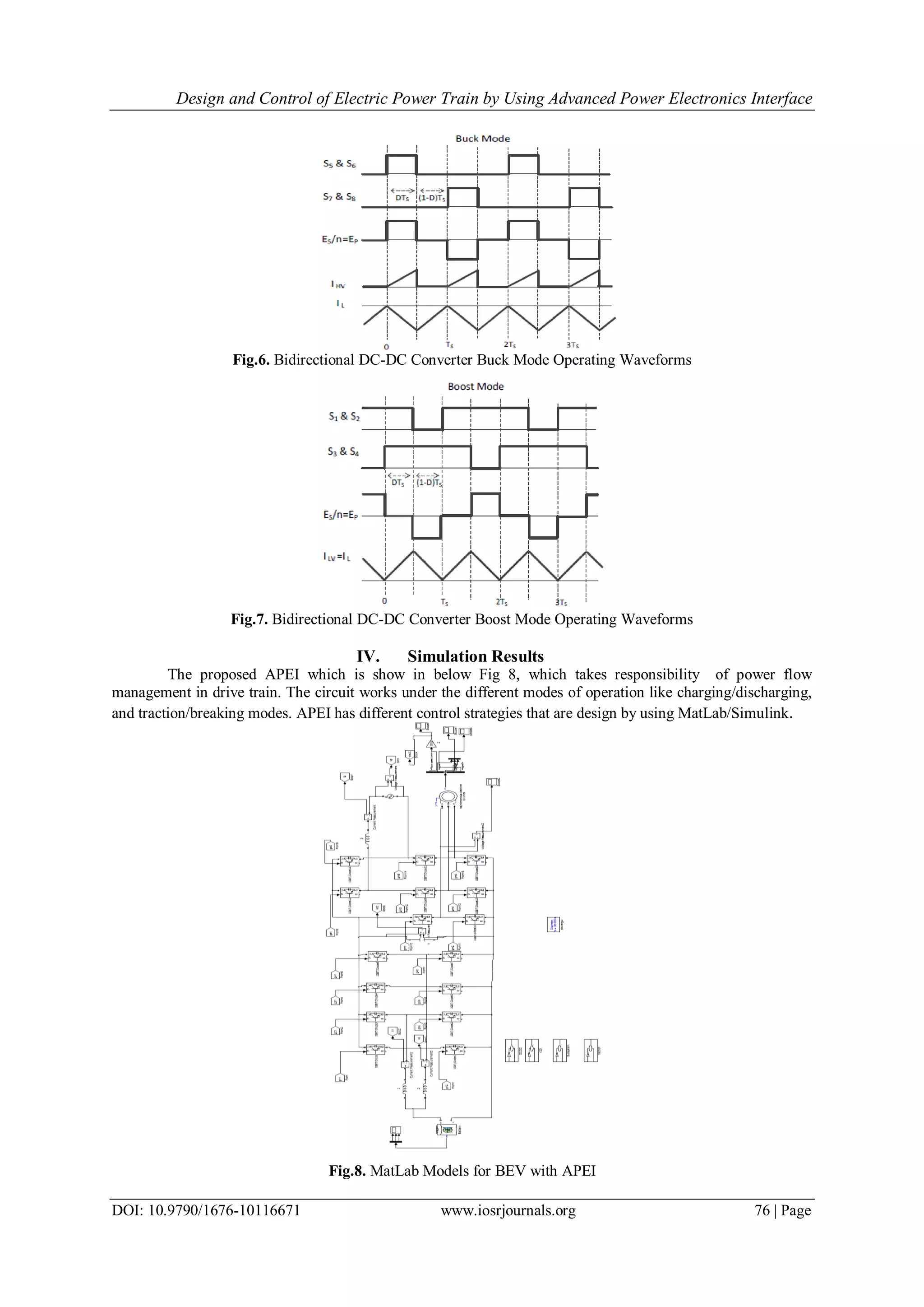
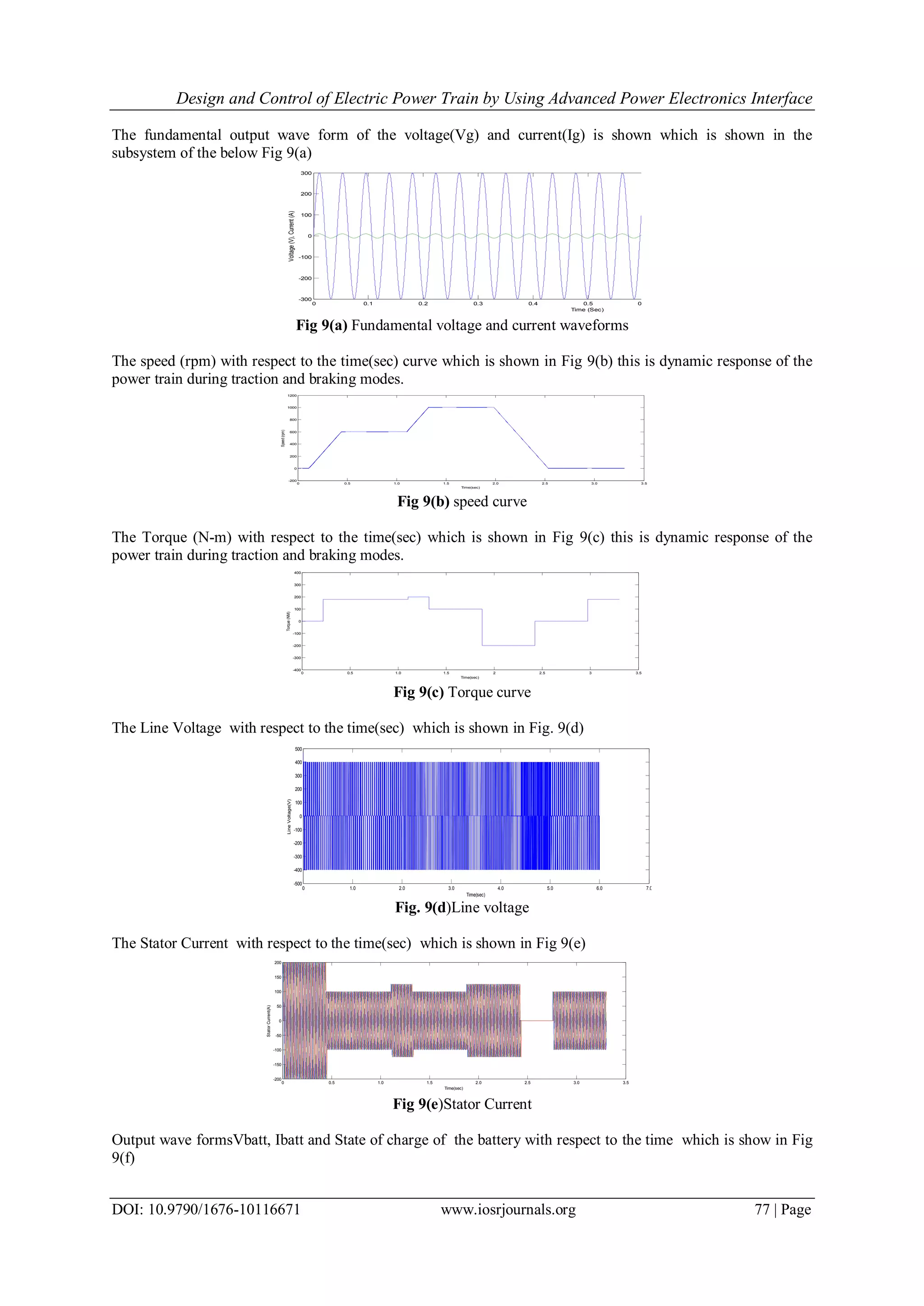
The gating signals and key operating waveforms as well as the converter current paths for the boost and
buck modes of operation for the bidirectional DC-DC converter are presented in above Fig.5 The currents IHV
and ILV are measured using the reference of „going into the converter‟ as the positive direction, which is why IL
is negative in buck mode and positive in boost mode. In boost mode only one current wave form is displayed. .
Bidirectional DC-DC Converter Buck/Boost Mode Operating Waveforms are shown in Fig 6 and Fig 7.
Design and Control of Electric Power Train by Using Advanced Power Electronics Interface
DOI: 10.9790/1676-10116671 www.iosrjournals.org 76 | Page
Fig.6. Bidirectional DC-DC Converter Buck Mode Operating Waveforms
Fig.7. Bidirectional DC-DC Converter Boost Mode Operating Waveforms
IV. Simulation Results
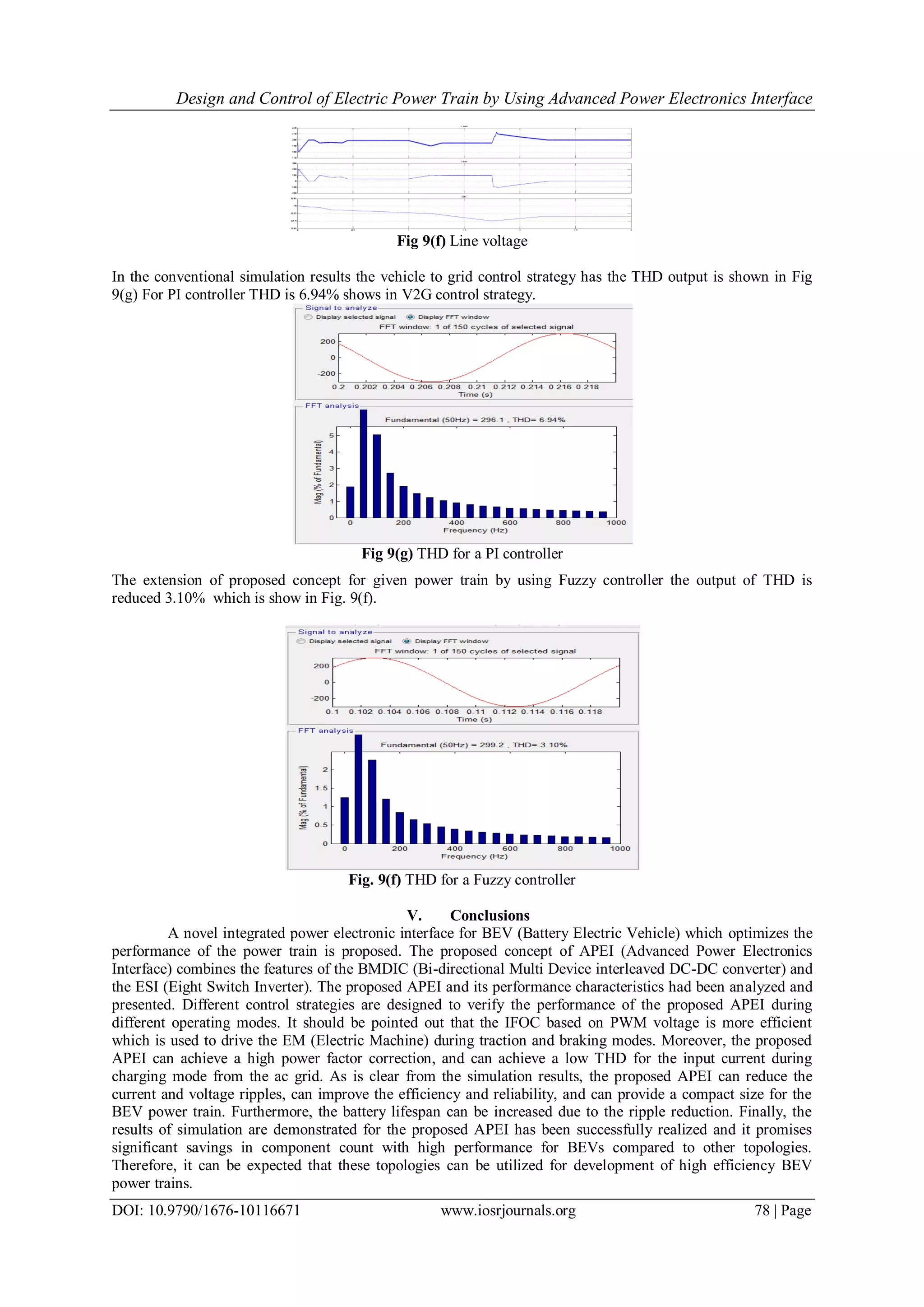
The proposed APEI which is show in below Fig 8, which takes responsibility of power flow
management in drive train. The circuit works under the different modes of operation like charging/discharging,
and traction/breaking modes. APEI has different control strategies that are design by using MatLab/Simulink.
Fig.8. MatLab Models for BEV with APEI
Design and Control of Electric Power Train by Using Advanced Power Electronics Interface
DOI: 10.9790/1676-10116671 www.iosrjournals.org 77 | Page
The fundamental output wave form of the voltage(Vg) and current(Ig) is shown which is shown in the
subsystem of the below Fig 9(a)
Fig 9(a) Fundamental voltage and current waveforms
The speed (rpm) with respect to the time(sec) curve which is shown in Fig 9(b) this is dynamic response of the
power train during traction and braking modes.
Fig 9(b) speed curve
The Torque (N-m) with respect to the time(sec) which is shown in Fig 9(c) this is dynamic response of the
power train during traction and braking modes.
Fig 9(c) Torque curve
The Line Voltage with respect to the time(sec) which is shown in Fig. 9(d)
Fig. 9(d)Line voltage
The Stator Current with respect to the time(sec) which is shown in Fig 9(e)
Fig 9(e)Stator Current
Output wave formsVbatt, Ibatt and State of charge of the battery with respect to the time which is show in Fig
9(f)
0 0.1 0.2 0.3 0.4 0.5 0.6 0.7 0.8 0.9 1.0
-300
-200
-100
0
100
200
300
Time (Sec)
Voltage(V),Current(A)
V
I
0 0.5 1.0 1.5 2.0 2.5 3.0 3.5
-200
0
200
400
600
800
1000
1200
Time(sec)
Speed(rpm)
0 0.5 1.0 1.5 2 2.5 3 3.5
-400
-300
-200
-100
0
100
200
300
400
Time(sec)
Torque(NM)
0 1.0 2.0 3.0 4.0 5.0 6.0 7.0
-500
-400
-300
-200
-100
0
100
200
300
400
500
Time(sec)
LineVoltage(V)
0 0.5 1.0 1.5 2.0 2.5 3.0 3.5
-200
-150
-100
-50
0
50
100
150
200
Time(sec)
StatorCurrent(A)
Design and Control of Electric Power Train by Using Advanced Power Electronics Interface
DOI: 10.9790/1676-10116671 www.iosrjournals.org 78 | Page
Fig 9(f) Line voltage
In the conventional simulation results the vehicle to grid control strategy has the THD output is shown in Fig
9(g) For PI controller THD is 6.94% shows in V2G control strategy.
Fig 9(g) THD for a PI controller
The extension of proposed concept for given power train by using Fuzzy controller the output of THD is
reduced 3.10% which is show in Fig. 9(f).
Fig. 9(f) THD for a Fuzzy controller
V. Conclusions
A novel integrated power electronic interface for BEV (Battery Electric Vehicle) which optimizes the
performance of the power train is proposed. The proposed concept of APEI (Advanced Power Electronics
Interface) combines the features of the BMDIC (Bi-directional Multi Device interleaved DC-DC converter) and
the ESI (Eight Switch Inverter). The proposed APEI and its performance characteristics had been analyzed and
presented. Different control strategies are designed to verify the performance of the proposed APEI during
different operating modes. It should be pointed out that the IFOC based on PWM voltage is more efficient
which is used to drive the EM (Electric Machine) during traction and braking modes. Moreover, the proposed
APEI can achieve a high power factor correction, and can achieve a low THD for the input current during
charging mode from the ac grid. As is clear from the simulation results, the proposed APEI can reduce the
current and voltage ripples, can improve the efficiency and reliability, and can provide a compact size for the
BEV power train. Furthermore, the battery lifespan can be increased due to the ripple reduction. Finally, the
results of simulation are demonstrated for the proposed APEI has been successfully realized and it promises
significant savings in component count with high performance for BEVs compared to other topologies.
Therefore, it can be expected that these topologies can be utilized for development of high efficiency BEV
power trains.
Design and Control of Electric Power Train by Using Advanced Power Electronics Interface
DOI: 10.9790/1676-10116671 www.iosrjournals.org 79 | Page
References
[1]. C. C. Chan, A. Bouscayrol, and K. Chen, “Electric, hybrid, and fuel-cell vehicles: Architectures and modeling,” IEEE Trans. Veh.
Technol., vol. 59, no. 2, pp. 589–598, Feb. 2010.
[2]. C. C. Chan, “The state of the art of electric and hybrid, and fuel cell vehicles,”Proc. IEEE, vol. 95, no. 4, pp. 704–718, Apr. 2007.
[3]. A. Emadi, S. S. Williamson, and A. Khaligh, “Power electronics intensive solutions for advanced electric, hybrid electric, and fuel
cell vehicular power systems,”IEEE Trans. Power Electron., vol. 21, no. 3, pp. 567– 577, May 2006.
[4]. A. Emadi, Y. J. Lee, and K. Rajashekara, “Power electronics and motor drives in electric, hybrid electric, and plug-in hybrid electric
vehicles,” IEEE Trans. Ind. Electron, vol. 55, no. 6, pp. 2237–2245, Jun. 2008.
[5]. S. S. Raghavan, O. C. Onar, and A. Khaligh, “Power electronic interfaces for future plug-in transportation systems,” IEEE Power
Electron. Soc. Newsletter, vol. 23, Third Quarter 2010.
[6]. Y.-J. Lee, A. Khaligh, and A. Emadi, “Advanced integrated bidirectional AC-DC and DC-DC converter for plug-in hybrid electric
vehicles,” IEEE Trans. Veh. Technol., vol. 58, no. 8, pp. 3970–3980, Oct. 2009.
[7]. M. Pahlevaninezhad, P. Das, J. Drobnik, P. K. Jain, and A. Bakhshai, “A new control approach based on the differential flatness
theory for an AC/DC converter used in electric vehicles,” IEEE Trans. Power Electron., vol. 27, no. 4, pp. 2085–2103, Apr. 2012.
[8]. Z-Source Inverter for Fuel Cell Vehicles, Oak Ridge Nat. Lab., Oak Ridge, TN, USA, Sep. 2005.
[9]. S. Miaosen, “Z-source inverter design, analysis, and its application in fuel cell vehicles,” Ph.D. dissertation, Michigan State Univ.,
East Lansing, USA, 2007.
[10]. M.-K. Nguyen, Y.-C. Lim, and G.-B. Cho, “Switched-inductor quasi-Zsource inverter, ” IEEE Transaction.power electron volume
no.26 pp.3183– 3191, Nov. 2011.
[11]. W. Kramer, S. Chakra borty, B. Kroposki, and H. Thomas, “Advanced power electronic interfaces for distributed energy systems,
Part 1: Systems and topologies,” National Renewable Energy Lab., Golden, CO, USA, Tech. Rep. F4, Nov. 2008.
[12]. O. Hegazy, J. Van Mierlo, and P. Lataire, “Control and analysis of an integrated bidirectional DC/AC and DC/DC converters for
plug-in hybrid electric vehicle applications,”J. Power Electron., vol. 11, no. 4, pp. 408– 417, 2011.
[13]. B. Gu, J.-S. Lai, N. Kees, and C. Zheng, “Hybrid-switching full-bridge DC–DC converter with minimal voltage stress of bridge
rectifier, reduced.

More Related Content

What's hot

6.[36 45]seven level modified cascaded inverter for induction motor drive app...
6.[36 45]seven level modified cascaded inverter for induction motor drive app...6.[36 45]seven level modified cascaded inverter for induction motor drive app...
6.[36 45]seven level modified cascaded inverter for induction motor drive app...Alexander Decker
 
Development of Regenerative Braking Concept for Electric Vehicle Enhanced wit...
Development of Regenerative Braking Concept for Electric Vehicle Enhanced wit...Development of Regenerative Braking Concept for Electric Vehicle Enhanced wit...
Development of Regenerative Braking Concept for Electric Vehicle Enhanced wit...
International Journal of Power Electronics and Drive Systems
 
IRJET- Enhancement in the Modelling of Braking System with Regenerative Metho...
IRJET- Enhancement in the Modelling of Braking System with Regenerative Metho...IRJET- Enhancement in the Modelling of Braking System with Regenerative Metho...
IRJET- Enhancement in the Modelling of Braking System with Regenerative Metho...
IRJET Journal
 
Design and Simulation of Efficient DC-DC Converter Topology for a Solar PV Mo...
Design and Simulation of Efficient DC-DC Converter Topology for a Solar PV Mo...Design and Simulation of Efficient DC-DC Converter Topology for a Solar PV Mo...
Design and Simulation of Efficient DC-DC Converter Topology for a Solar PV Mo...
Sajin Ismail
 
Maximum Power Point Tracking Charge Controller for Standalone PV System
Maximum Power Point Tracking Charge Controller for Standalone PV SystemMaximum Power Point Tracking Charge Controller for Standalone PV System
Maximum Power Point Tracking Charge Controller for Standalone PV System
TELKOMNIKA JOURNAL
 
Improving Electromagnetic Compatibility and Better Harmonic Performance by Us...
Improving Electromagnetic Compatibility and Better Harmonic Performance by Us...Improving Electromagnetic Compatibility and Better Harmonic Performance by Us...
Improving Electromagnetic Compatibility and Better Harmonic Performance by Us...
rnvsubbarao koppineni
 
Comparison of Multicarrier PWM Techniques for Cascaded H-Bridge Multilevel In...
Comparison of Multicarrier PWM Techniques for Cascaded H-Bridge Multilevel In...Comparison of Multicarrier PWM Techniques for Cascaded H-Bridge Multilevel In...
Comparison of Multicarrier PWM Techniques for Cascaded H-Bridge Multilevel In...
International Journal of Power Electronics and Drive Systems
 
IRJET- Power Management System for Electric Vehicle Charging Stations using F...
IRJET- Power Management System for Electric Vehicle Charging Stations using F...IRJET- Power Management System for Electric Vehicle Charging Stations using F...
IRJET- Power Management System for Electric Vehicle Charging Stations using F...
IRJET Journal
 
K010327983
K010327983K010327983
K010327983
IOSR Journals
 
C1102031116
C1102031116C1102031116
C1102031116
IOSR Journals
 
Conceptual study on Grid-to-Vehicle (G2V) wireless power transfer using singl...
Conceptual study on Grid-to-Vehicle (G2V) wireless power transfer using singl...Conceptual study on Grid-to-Vehicle (G2V) wireless power transfer using singl...
Conceptual study on Grid-to-Vehicle (G2V) wireless power transfer using singl...
International Journal of Power Electronics and Drive Systems
 
A Comprehensive Analysis of Partial Shading Effect on Output Parameters of a ...
A Comprehensive Analysis of Partial Shading Effect on Output Parameters of a ...A Comprehensive Analysis of Partial Shading Effect on Output Parameters of a ...
A Comprehensive Analysis of Partial Shading Effect on Output Parameters of a ...
IJECEIAES
 
Partial Shading Detection and MPPT Controller for Total Cross Tied Photovolta...
Partial Shading Detection and MPPT Controller for Total Cross Tied Photovolta...Partial Shading Detection and MPPT Controller for Total Cross Tied Photovolta...
Partial Shading Detection and MPPT Controller for Total Cross Tied Photovolta...
IDES Editor
 
C010231319
C010231319C010231319
C010231319
IOSR Journals
 
Power loss analysis of current-modules based multilevel current-source power ...
Power loss analysis of current-modules based multilevel current-source power ...Power loss analysis of current-modules based multilevel current-source power ...
Power loss analysis of current-modules based multilevel current-source power ...
TELKOMNIKA JOURNAL
 
IEEE Conference Paper
IEEE Conference PaperIEEE Conference Paper
IEEE Conference PaperKoki Ogura
 
Development of multiple plug-in electric vehicle mobile charging station usin...
Development of multiple plug-in electric vehicle mobile charging station usin...Development of multiple plug-in electric vehicle mobile charging station usin...
Development of multiple plug-in electric vehicle mobile charging station usin...
International Journal of Power Electronics and Drive Systems
 
Optimal placement of custom power devices in power
Optimal placement of custom power devices in powerOptimal placement of custom power devices in power
Optimal placement of custom power devices in poweriaemedu
 

What's hot (18)

6.[36 45]seven level modified cascaded inverter for induction motor drive app...
6.[36 45]seven level modified cascaded inverter for induction motor drive app...6.[36 45]seven level modified cascaded inverter for induction motor drive app...
6.[36 45]seven level modified cascaded inverter for induction motor drive app...
 
Development of Regenerative Braking Concept for Electric Vehicle Enhanced wit...
Development of Regenerative Braking Concept for Electric Vehicle Enhanced wit...Development of Regenerative Braking Concept for Electric Vehicle Enhanced wit...
Development of Regenerative Braking Concept for Electric Vehicle Enhanced wit...
 
IRJET- Enhancement in the Modelling of Braking System with Regenerative Metho...
IRJET- Enhancement in the Modelling of Braking System with Regenerative Metho...IRJET- Enhancement in the Modelling of Braking System with Regenerative Metho...
IRJET- Enhancement in the Modelling of Braking System with Regenerative Metho...
 
Design and Simulation of Efficient DC-DC Converter Topology for a Solar PV Mo...
Design and Simulation of Efficient DC-DC Converter Topology for a Solar PV Mo...Design and Simulation of Efficient DC-DC Converter Topology for a Solar PV Mo...
Design and Simulation of Efficient DC-DC Converter Topology for a Solar PV Mo...
 
Maximum Power Point Tracking Charge Controller for Standalone PV System
Maximum Power Point Tracking Charge Controller for Standalone PV SystemMaximum Power Point Tracking Charge Controller for Standalone PV System
Maximum Power Point Tracking Charge Controller for Standalone PV System
 
Improving Electromagnetic Compatibility and Better Harmonic Performance by Us...
Improving Electromagnetic Compatibility and Better Harmonic Performance by Us...Improving Electromagnetic Compatibility and Better Harmonic Performance by Us...
Improving Electromagnetic Compatibility and Better Harmonic Performance by Us...
 
Comparison of Multicarrier PWM Techniques for Cascaded H-Bridge Multilevel In...
Comparison of Multicarrier PWM Techniques for Cascaded H-Bridge Multilevel In...Comparison of Multicarrier PWM Techniques for Cascaded H-Bridge Multilevel In...
Comparison of Multicarrier PWM Techniques for Cascaded H-Bridge Multilevel In...
 
IRJET- Power Management System for Electric Vehicle Charging Stations using F...
IRJET- Power Management System for Electric Vehicle Charging Stations using F...IRJET- Power Management System for Electric Vehicle Charging Stations using F...
IRJET- Power Management System for Electric Vehicle Charging Stations using F...
 
K010327983
K010327983K010327983
K010327983
 
C1102031116
C1102031116C1102031116
C1102031116
 
Conceptual study on Grid-to-Vehicle (G2V) wireless power transfer using singl...
Conceptual study on Grid-to-Vehicle (G2V) wireless power transfer using singl...Conceptual study on Grid-to-Vehicle (G2V) wireless power transfer using singl...
Conceptual study on Grid-to-Vehicle (G2V) wireless power transfer using singl...
 
A Comprehensive Analysis of Partial Shading Effect on Output Parameters of a ...
A Comprehensive Analysis of Partial Shading Effect on Output Parameters of a ...A Comprehensive Analysis of Partial Shading Effect on Output Parameters of a ...
A Comprehensive Analysis of Partial Shading Effect on Output Parameters of a ...
 
Partial Shading Detection and MPPT Controller for Total Cross Tied Photovolta...
Partial Shading Detection and MPPT Controller for Total Cross Tied Photovolta...Partial Shading Detection and MPPT Controller for Total Cross Tied Photovolta...
Partial Shading Detection and MPPT Controller for Total Cross Tied Photovolta...
 
C010231319
C010231319C010231319
C010231319
 
Power loss analysis of current-modules based multilevel current-source power ...
Power loss analysis of current-modules based multilevel current-source power ...Power loss analysis of current-modules based multilevel current-source power ...
Power loss analysis of current-modules based multilevel current-source power ...
 
IEEE Conference Paper
IEEE Conference PaperIEEE Conference Paper
IEEE Conference Paper
 
Development of multiple plug-in electric vehicle mobile charging station usin...
Development of multiple plug-in electric vehicle mobile charging station usin...Development of multiple plug-in electric vehicle mobile charging station usin...
Development of multiple plug-in electric vehicle mobile charging station usin...
 
Optimal placement of custom power devices in power
Optimal placement of custom power devices in powerOptimal placement of custom power devices in power
Optimal placement of custom power devices in power
 

Similar to Design and Control of Electric Power Train by Using Advanced Power Electronics Interface

Enhancement of Voltage Stability by using Fuel Cell as Shunt Compensator
Enhancement of Voltage Stability by using Fuel Cell as Shunt CompensatorEnhancement of Voltage Stability by using Fuel Cell as Shunt Compensator
Enhancement of Voltage Stability by using Fuel Cell as Shunt Compensator
IRJET Journal
 
Design of Electric Drive for Vehicular Application Using Vector Control
Design of Electric Drive for Vehicular Application Using Vector ControlDesign of Electric Drive for Vehicular Application Using Vector Control
Design of Electric Drive for Vehicular Application Using Vector Control
IOSR Journals
 
Designing a Power Sharing Control Algorithm to Integrate the Fuel Cell into a...
Designing a Power Sharing Control Algorithm to Integrate the Fuel Cell into a...Designing a Power Sharing Control Algorithm to Integrate the Fuel Cell into a...
Designing a Power Sharing Control Algorithm to Integrate the Fuel Cell into a...
IRJET Journal
 
DESIGN OF A MULTIFUNCTIONAL FLYBACK DC-DC CONVERTER WITH CURRENT CONTROL
DESIGN OF A MULTIFUNCTIONAL FLYBACK DC-DC CONVERTER WITH CURRENT CONTROLDESIGN OF A MULTIFUNCTIONAL FLYBACK DC-DC CONVERTER WITH CURRENT CONTROL
DESIGN OF A MULTIFUNCTIONAL FLYBACK DC-DC CONVERTER WITH CURRENT CONTROL
IAEME Publication
 
Comparison of solar based closed loop DC-DC converter using PID and ANN contr...
Comparison of solar based closed loop DC-DC converter using PID and ANN contr...Comparison of solar based closed loop DC-DC converter using PID and ANN contr...
Comparison of solar based closed loop DC-DC converter using PID and ANN contr...
International Journal of Power Electronics and Drive Systems
 
Tpel.2005.854020
Tpel.2005.854020Tpel.2005.854020
Tpel.2005.854020
PrafulYadav4
 
Performance enhancement of DC/DC converters for solar powered EV
Performance enhancement of DC/DC converters for solar powered EV Performance enhancement of DC/DC converters for solar powered EV
Performance enhancement of DC/DC converters for solar powered EV
IJECEIAES
 
Interleaved Boost Converter Fed with PV for Induction Motor/Agricultural Appl...
Interleaved Boost Converter Fed with PV for Induction Motor/Agricultural Appl...Interleaved Boost Converter Fed with PV for Induction Motor/Agricultural Appl...
Interleaved Boost Converter Fed with PV for Induction Motor/Agricultural Appl...
IAES-IJPEDS
 
Modeling and control of a hybrid DC/DC/AC converter to transfer power under d...
Modeling and control of a hybrid DC/DC/AC converter to transfer power under d...Modeling and control of a hybrid DC/DC/AC converter to transfer power under d...
Modeling and control of a hybrid DC/DC/AC converter to transfer power under d...
International Journal of Power Electronics and Drive Systems
 
IRJET - Design of Power Converters for Renewable Energy Sources and Electric ...
IRJET - Design of Power Converters for Renewable Energy Sources and Electric ...IRJET - Design of Power Converters for Renewable Energy Sources and Electric ...
IRJET - Design of Power Converters for Renewable Energy Sources and Electric ...
IRJET Journal
 
A Integrated Technique of SIDO PFC Fly back Converter in power system
A Integrated Technique of SIDO PFC Fly back Converter in power systemA Integrated Technique of SIDO PFC Fly back Converter in power system
A Integrated Technique of SIDO PFC Fly back Converter in power system
IJMTST Journal
 
Design and Performance of a Bidirectional Isolated Dc-Dc Converter for Renewa...
Design and Performance of a Bidirectional Isolated Dc-Dc Converter for Renewa...Design and Performance of a Bidirectional Isolated Dc-Dc Converter for Renewa...
Design and Performance of a Bidirectional Isolated Dc-Dc Converter for Renewa...
IOSR Journals
 
Hybrid Energy System using Non Isolated Dc –Dc Converter
Hybrid Energy System using Non Isolated Dc –Dc ConverterHybrid Energy System using Non Isolated Dc –Dc Converter
Hybrid Energy System using Non Isolated Dc –Dc Converter
IRJET Journal
 
HIGH EFFICIENT BRIDGELESS BOOST RECTIFIER FOR LOW VOLTAGE ENERGY HARVESTING A...
HIGH EFFICIENT BRIDGELESS BOOST RECTIFIER FOR LOW VOLTAGE ENERGY HARVESTING A...HIGH EFFICIENT BRIDGELESS BOOST RECTIFIER FOR LOW VOLTAGE ENERGY HARVESTING A...
HIGH EFFICIENT BRIDGELESS BOOST RECTIFIER FOR LOW VOLTAGE ENERGY HARVESTING A...
IAEME Publication
 
An Efficient Wireless Power Transfer Methodology for Electric Vehicle Battery...
An Efficient Wireless Power Transfer Methodology for Electric Vehicle Battery...An Efficient Wireless Power Transfer Methodology for Electric Vehicle Battery...
An Efficient Wireless Power Transfer Methodology for Electric Vehicle Battery...
IRJET Journal
 
DC-DC converter based power management for go green applications
DC-DC converter based power management for go green applicationsDC-DC converter based power management for go green applications
DC-DC converter based power management for go green applications
International Journal of Power Electronics and Drive Systems
 
Performance Analysis of DC Micro Grid with PV-Fuel Cell Hybrid Generation
Performance Analysis of DC Micro Grid with PV-Fuel Cell Hybrid GenerationPerformance Analysis of DC Micro Grid with PV-Fuel Cell Hybrid Generation
Performance Analysis of DC Micro Grid with PV-Fuel Cell Hybrid Generation
IJMREMJournal
 
Design and operation of closed-loop triple-deck buck-boost converter with hig...
Design and operation of closed-loop triple-deck buck-boost converter with hig...Design and operation of closed-loop triple-deck buck-boost converter with hig...
Design and operation of closed-loop triple-deck buck-boost converter with hig...
International Journal of Power Electronics and Drive Systems
 
IRJET- Design of Power Factor Correction Controller using Buck-Boost Converte...
IRJET- Design of Power Factor Correction Controller using Buck-Boost Converte...IRJET- Design of Power Factor Correction Controller using Buck-Boost Converte...
IRJET- Design of Power Factor Correction Controller using Buck-Boost Converte...
IRJET Journal
 
Efficient bridgeless SEPIC converter fed PMBLDC motor using artificial neural...
Efficient bridgeless SEPIC converter fed PMBLDC motor using artificial neural...Efficient bridgeless SEPIC converter fed PMBLDC motor using artificial neural...
Efficient bridgeless SEPIC converter fed PMBLDC motor using artificial neural...
IJECEIAES
 

Similar to Design and Control of Electric Power Train by Using Advanced Power Electronics Interface (20)

Enhancement of Voltage Stability by using Fuel Cell as Shunt Compensator
Enhancement of Voltage Stability by using Fuel Cell as Shunt CompensatorEnhancement of Voltage Stability by using Fuel Cell as Shunt Compensator
Enhancement of Voltage Stability by using Fuel Cell as Shunt Compensator
 
Design of Electric Drive for Vehicular Application Using Vector Control
Design of Electric Drive for Vehicular Application Using Vector ControlDesign of Electric Drive for Vehicular Application Using Vector Control
Design of Electric Drive for Vehicular Application Using Vector Control
 
Designing a Power Sharing Control Algorithm to Integrate the Fuel Cell into a...
Designing a Power Sharing Control Algorithm to Integrate the Fuel Cell into a...Designing a Power Sharing Control Algorithm to Integrate the Fuel Cell into a...
Designing a Power Sharing Control Algorithm to Integrate the Fuel Cell into a...
 
DESIGN OF A MULTIFUNCTIONAL FLYBACK DC-DC CONVERTER WITH CURRENT CONTROL
DESIGN OF A MULTIFUNCTIONAL FLYBACK DC-DC CONVERTER WITH CURRENT CONTROLDESIGN OF A MULTIFUNCTIONAL FLYBACK DC-DC CONVERTER WITH CURRENT CONTROL
DESIGN OF A MULTIFUNCTIONAL FLYBACK DC-DC CONVERTER WITH CURRENT CONTROL
 
Comparison of solar based closed loop DC-DC converter using PID and ANN contr...
Comparison of solar based closed loop DC-DC converter using PID and ANN contr...Comparison of solar based closed loop DC-DC converter using PID and ANN contr...
Comparison of solar based closed loop DC-DC converter using PID and ANN contr...
 
Tpel.2005.854020
Tpel.2005.854020Tpel.2005.854020
Tpel.2005.854020
 
Performance enhancement of DC/DC converters for solar powered EV
Performance enhancement of DC/DC converters for solar powered EV Performance enhancement of DC/DC converters for solar powered EV
Performance enhancement of DC/DC converters for solar powered EV
 
Interleaved Boost Converter Fed with PV for Induction Motor/Agricultural Appl...
Interleaved Boost Converter Fed with PV for Induction Motor/Agricultural Appl...Interleaved Boost Converter Fed with PV for Induction Motor/Agricultural Appl...
Interleaved Boost Converter Fed with PV for Induction Motor/Agricultural Appl...
 
Modeling and control of a hybrid DC/DC/AC converter to transfer power under d...
Modeling and control of a hybrid DC/DC/AC converter to transfer power under d...Modeling and control of a hybrid DC/DC/AC converter to transfer power under d...
Modeling and control of a hybrid DC/DC/AC converter to transfer power under d...
 
IRJET - Design of Power Converters for Renewable Energy Sources and Electric ...
IRJET - Design of Power Converters for Renewable Energy Sources and Electric ...IRJET - Design of Power Converters for Renewable Energy Sources and Electric ...
IRJET - Design of Power Converters for Renewable Energy Sources and Electric ...
 
A Integrated Technique of SIDO PFC Fly back Converter in power system
A Integrated Technique of SIDO PFC Fly back Converter in power systemA Integrated Technique of SIDO PFC Fly back Converter in power system
A Integrated Technique of SIDO PFC Fly back Converter in power system
 
Design and Performance of a Bidirectional Isolated Dc-Dc Converter for Renewa...
Design and Performance of a Bidirectional Isolated Dc-Dc Converter for Renewa...Design and Performance of a Bidirectional Isolated Dc-Dc Converter for Renewa...
Design and Performance of a Bidirectional Isolated Dc-Dc Converter for Renewa...
 
Hybrid Energy System using Non Isolated Dc –Dc Converter
Hybrid Energy System using Non Isolated Dc –Dc ConverterHybrid Energy System using Non Isolated Dc –Dc Converter
Hybrid Energy System using Non Isolated Dc –Dc Converter
 
HIGH EFFICIENT BRIDGELESS BOOST RECTIFIER FOR LOW VOLTAGE ENERGY HARVESTING A...
HIGH EFFICIENT BRIDGELESS BOOST RECTIFIER FOR LOW VOLTAGE ENERGY HARVESTING A...HIGH EFFICIENT BRIDGELESS BOOST RECTIFIER FOR LOW VOLTAGE ENERGY HARVESTING A...
HIGH EFFICIENT BRIDGELESS BOOST RECTIFIER FOR LOW VOLTAGE ENERGY HARVESTING A...
 
An Efficient Wireless Power Transfer Methodology for Electric Vehicle Battery...
An Efficient Wireless Power Transfer Methodology for Electric Vehicle Battery...An Efficient Wireless Power Transfer Methodology for Electric Vehicle Battery...
An Efficient Wireless Power Transfer Methodology for Electric Vehicle Battery...
 
DC-DC converter based power management for go green applications
DC-DC converter based power management for go green applicationsDC-DC converter based power management for go green applications
DC-DC converter based power management for go green applications
 
Performance Analysis of DC Micro Grid with PV-Fuel Cell Hybrid Generation
Performance Analysis of DC Micro Grid with PV-Fuel Cell Hybrid GenerationPerformance Analysis of DC Micro Grid with PV-Fuel Cell Hybrid Generation
Performance Analysis of DC Micro Grid with PV-Fuel Cell Hybrid Generation
 
Design and operation of closed-loop triple-deck buck-boost converter with hig...
Design and operation of closed-loop triple-deck buck-boost converter with hig...Design and operation of closed-loop triple-deck buck-boost converter with hig...
Design and operation of closed-loop triple-deck buck-boost converter with hig...
 
IRJET- Design of Power Factor Correction Controller using Buck-Boost Converte...
IRJET- Design of Power Factor Correction Controller using Buck-Boost Converte...IRJET- Design of Power Factor Correction Controller using Buck-Boost Converte...
IRJET- Design of Power Factor Correction Controller using Buck-Boost Converte...
 
Efficient bridgeless SEPIC converter fed PMBLDC motor using artificial neural...
Efficient bridgeless SEPIC converter fed PMBLDC motor using artificial neural...Efficient bridgeless SEPIC converter fed PMBLDC motor using artificial neural...
Efficient bridgeless SEPIC converter fed PMBLDC motor using artificial neural...
 

More from IOSR Journals

A011140104
A011140104A011140104
A011140104
IOSR Journals
 
M0111397100
M0111397100M0111397100
M0111397100
IOSR Journals
 
L011138596
L011138596L011138596
L011138596
IOSR Journals
 
K011138084
K011138084K011138084
K011138084
IOSR Journals
 
J011137479
J011137479J011137479
J011137479
IOSR Journals
 
I011136673
I011136673I011136673
I011136673
IOSR Journals
 
G011134454
G011134454G011134454
G011134454
IOSR Journals
 
H011135565
H011135565H011135565
H011135565
IOSR Journals
 
F011134043
F011134043F011134043
F011134043
IOSR Journals
 
E011133639
E011133639E011133639
E011133639
IOSR Journals
 
D011132635
D011132635D011132635
D011132635
IOSR Journals
 
C011131925
C011131925C011131925
C011131925
IOSR Journals
 
B011130918
B011130918B011130918
B011130918
IOSR Journals
 
A011130108
A011130108A011130108
A011130108
IOSR Journals
 
I011125160
I011125160I011125160
I011125160
IOSR Journals
 
H011124050
H011124050H011124050
H011124050
IOSR Journals
 
G011123539
G011123539G011123539
G011123539
IOSR Journals
 
F011123134
F011123134F011123134
F011123134
IOSR Journals
 
E011122530
E011122530E011122530
E011122530
IOSR Journals
 
D011121524
D011121524D011121524
D011121524
IOSR Journals
 

More from IOSR Journals (20)

A011140104
A011140104A011140104
A011140104
 
M0111397100
M0111397100M0111397100
M0111397100
 
L011138596
L011138596L011138596
L011138596
 
K011138084
K011138084K011138084
K011138084
 
J011137479
J011137479J011137479
J011137479
 
I011136673
I011136673I011136673
I011136673
 
G011134454
G011134454G011134454
G011134454
 
H011135565
H011135565H011135565
H011135565
 
F011134043
F011134043F011134043
F011134043
 
E011133639
E011133639E011133639
E011133639
 
D011132635
D011132635D011132635
D011132635
 
C011131925
C011131925C011131925
C011131925
 
B011130918
B011130918B011130918
B011130918
 
A011130108
A011130108A011130108
A011130108
 
I011125160
I011125160I011125160
I011125160
 
H011124050
H011124050H011124050
H011124050
 
G011123539
G011123539G011123539
G011123539
 
F011123134
F011123134F011123134
F011123134
 
E011122530
E011122530E011122530
E011122530
 
D011121524
D011121524D011121524
D011121524
 

Recently uploaded

Top 10 Oil and Gas Projects in Saudi Arabia 2024.pdf
Top 10 Oil and Gas Projects in Saudi Arabia 2024.pdfTop 10 Oil and Gas Projects in Saudi Arabia 2024.pdf
Top 10 Oil and Gas Projects in Saudi Arabia 2024.pdf
Teleport Manpower Consultant
 
Building Electrical System Design & Installation
Building Electrical System Design & InstallationBuilding Electrical System Design & Installation
Building Electrical System Design & Installation
symbo111
 
Tutorial for 16S rRNA Gene Analysis with QIIME2.pdf
Tutorial for 16S rRNA Gene Analysis with QIIME2.pdfTutorial for 16S rRNA Gene Analysis with QIIME2.pdf
Tutorial for 16S rRNA Gene Analysis with QIIME2.pdf
aqil azizi
 
14 Template Contractual Notice - EOT Application
14 Template Contractual Notice - EOT Application14 Template Contractual Notice - EOT Application
14 Template Contractual Notice - EOT Application
SyedAbiiAzazi1
 
AKS UNIVERSITY Satna Final Year Project By OM Hardaha.pdf
AKS UNIVERSITY Satna Final Year Project By OM Hardaha.pdfAKS UNIVERSITY Satna Final Year Project By OM Hardaha.pdf
AKS UNIVERSITY Satna Final Year Project By OM Hardaha.pdf
SamSarthak3
 
一比一原版(UofT毕业证)多伦多大学毕业证成绩单如何办理
一比一原版(UofT毕业证)多伦多大学毕业证成绩单如何办理一比一原版(UofT毕业证)多伦多大学毕业证成绩单如何办理
一比一原版(UofT毕业证)多伦多大学毕业证成绩单如何办理
ydteq
 
Fundamentals of Electric Drives and its applications.pptx
Fundamentals of Electric Drives and its applications.pptxFundamentals of Electric Drives and its applications.pptx
Fundamentals of Electric Drives and its applications.pptx
manasideore6
 
Recycled Concrete Aggregate in Construction Part III
Recycled Concrete Aggregate in Construction Part IIIRecycled Concrete Aggregate in Construction Part III
Recycled Concrete Aggregate in Construction Part III
Aditya Rajan Patra
 
Unbalanced Three Phase Systems and circuits.pptx
Unbalanced Three Phase Systems and circuits.pptxUnbalanced Three Phase Systems and circuits.pptx
Unbalanced Three Phase Systems and circuits.pptx
ChristineTorrepenida1
 
DfMAy 2024 - key insights and contributions
DfMAy 2024 - key insights and contributionsDfMAy 2024 - key insights and contributions
DfMAy 2024 - key insights and contributions
gestioneergodomus
 
Final project report on grocery store management system..pdf
Final project report on grocery store management system..pdfFinal project report on grocery store management system..pdf
Final project report on grocery store management system..pdf
Kamal Acharya
 
RAT: Retrieval Augmented Thoughts Elicit Context-Aware Reasoning in Long-Hori...
RAT: Retrieval Augmented Thoughts Elicit Context-Aware Reasoning in Long-Hori...RAT: Retrieval Augmented Thoughts Elicit Context-Aware Reasoning in Long-Hori...
RAT: Retrieval Augmented Thoughts Elicit Context-Aware Reasoning in Long-Hori...
thanhdowork
 
Immunizing Image Classifiers Against Localized Adversary Attacks
Immunizing Image Classifiers Against Localized Adversary AttacksImmunizing Image Classifiers Against Localized Adversary Attacks
Immunizing Image Classifiers Against Localized Adversary Attacks
gerogepatton
 
NUMERICAL SIMULATIONS OF HEAT AND MASS TRANSFER IN CONDENSING HEAT EXCHANGERS...
NUMERICAL SIMULATIONS OF HEAT AND MASS TRANSFER IN CONDENSING HEAT EXCHANGERS...NUMERICAL SIMULATIONS OF HEAT AND MASS TRANSFER IN CONDENSING HEAT EXCHANGERS...
NUMERICAL SIMULATIONS OF HEAT AND MASS TRANSFER IN CONDENSING HEAT EXCHANGERS...
ssuser7dcef0
 
MCQ Soil mechanics questions (Soil shear strength).pdf
MCQ Soil mechanics questions (Soil shear strength).pdfMCQ Soil mechanics questions (Soil shear strength).pdf
MCQ Soil mechanics questions (Soil shear strength).pdf
Osamah Alsalih
 
Hybrid optimization of pumped hydro system and solar- Engr. Abdul-Azeez.pdf
Hybrid optimization of pumped hydro system and solar- Engr. Abdul-Azeez.pdfHybrid optimization of pumped hydro system and solar- Engr. Abdul-Azeez.pdf
Hybrid optimization of pumped hydro system and solar- Engr. Abdul-Azeez.pdf
fxintegritypublishin
 
Heap Sort (SS).ppt FOR ENGINEERING GRADUATES, BCA, MCA, MTECH, BSC STUDENTS
Heap Sort (SS).ppt FOR ENGINEERING GRADUATES, BCA, MCA, MTECH, BSC STUDENTSHeap Sort (SS).ppt FOR ENGINEERING GRADUATES, BCA, MCA, MTECH, BSC STUDENTS
Heap Sort (SS).ppt FOR ENGINEERING GRADUATES, BCA, MCA, MTECH, BSC STUDENTS
Soumen Santra
 
block diagram and signal flow graph representation
block diagram and signal flow graph representationblock diagram and signal flow graph representation
block diagram and signal flow graph representation
Divya Somashekar
 
Gen AI Study Jams _ For the GDSC Leads in India.pdf
Gen AI Study Jams _ For the GDSC Leads in India.pdfGen AI Study Jams _ For the GDSC Leads in India.pdf
Gen AI Study Jams _ For the GDSC Leads in India.pdf
gdsczhcet
 
Standard Reomte Control Interface - Neometrix
Standard Reomte Control Interface - NeometrixStandard Reomte Control Interface - Neometrix
Standard Reomte Control Interface - Neometrix
Neometrix_Engineering_Pvt_Ltd
 

Recently uploaded (20)

Top 10 Oil and Gas Projects in Saudi Arabia 2024.pdf
Top 10 Oil and Gas Projects in Saudi Arabia 2024.pdfTop 10 Oil and Gas Projects in Saudi Arabia 2024.pdf
Top 10 Oil and Gas Projects in Saudi Arabia 2024.pdf
 
Building Electrical System Design & Installation
Building Electrical System Design & InstallationBuilding Electrical System Design & Installation
Building Electrical System Design & Installation
 
Tutorial for 16S rRNA Gene Analysis with QIIME2.pdf
Tutorial for 16S rRNA Gene Analysis with QIIME2.pdfTutorial for 16S rRNA Gene Analysis with QIIME2.pdf
Tutorial for 16S rRNA Gene Analysis with QIIME2.pdf
 
14 Template Contractual Notice - EOT Application
14 Template Contractual Notice - EOT Application14 Template Contractual Notice - EOT Application
14 Template Contractual Notice - EOT Application
 
AKS UNIVERSITY Satna Final Year Project By OM Hardaha.pdf
AKS UNIVERSITY Satna Final Year Project By OM Hardaha.pdfAKS UNIVERSITY Satna Final Year Project By OM Hardaha.pdf
AKS UNIVERSITY Satna Final Year Project By OM Hardaha.pdf
 
一比一原版(UofT毕业证)多伦多大学毕业证成绩单如何办理
一比一原版(UofT毕业证)多伦多大学毕业证成绩单如何办理一比一原版(UofT毕业证)多伦多大学毕业证成绩单如何办理
一比一原版(UofT毕业证)多伦多大学毕业证成绩单如何办理
 
Fundamentals of Electric Drives and its applications.pptx
Fundamentals of Electric Drives and its applications.pptxFundamentals of Electric Drives and its applications.pptx
Fundamentals of Electric Drives and its applications.pptx
 
Recycled Concrete Aggregate in Construction Part III
Recycled Concrete Aggregate in Construction Part IIIRecycled Concrete Aggregate in Construction Part III
Recycled Concrete Aggregate in Construction Part III
 
Unbalanced Three Phase Systems and circuits.pptx
Unbalanced Three Phase Systems and circuits.pptxUnbalanced Three Phase Systems and circuits.pptx
Unbalanced Three Phase Systems and circuits.pptx
 
DfMAy 2024 - key insights and contributions
DfMAy 2024 - key insights and contributionsDfMAy 2024 - key insights and contributions
DfMAy 2024 - key insights and contributions
 
Final project report on grocery store management system..pdf
Final project report on grocery store management system..pdfFinal project report on grocery store management system..pdf
Final project report on grocery store management system..pdf
 
RAT: Retrieval Augmented Thoughts Elicit Context-Aware Reasoning in Long-Hori...
RAT: Retrieval Augmented Thoughts Elicit Context-Aware Reasoning in Long-Hori...RAT: Retrieval Augmented Thoughts Elicit Context-Aware Reasoning in Long-Hori...
RAT: Retrieval Augmented Thoughts Elicit Context-Aware Reasoning in Long-Hori...
 
Immunizing Image Classifiers Against Localized Adversary Attacks
Immunizing Image Classifiers Against Localized Adversary AttacksImmunizing Image Classifiers Against Localized Adversary Attacks
Immunizing Image Classifiers Against Localized Adversary Attacks
 
NUMERICAL SIMULATIONS OF HEAT AND MASS TRANSFER IN CONDENSING HEAT EXCHANGERS...
NUMERICAL SIMULATIONS OF HEAT AND MASS TRANSFER IN CONDENSING HEAT EXCHANGERS...NUMERICAL SIMULATIONS OF HEAT AND MASS TRANSFER IN CONDENSING HEAT EXCHANGERS...
NUMERICAL SIMULATIONS OF HEAT AND MASS TRANSFER IN CONDENSING HEAT EXCHANGERS...
 
MCQ Soil mechanics questions (Soil shear strength).pdf
MCQ Soil mechanics questions (Soil shear strength).pdfMCQ Soil mechanics questions (Soil shear strength).pdf
MCQ Soil mechanics questions (Soil shear strength).pdf
 
Hybrid optimization of pumped hydro system and solar- Engr. Abdul-Azeez.pdf
Hybrid optimization of pumped hydro system and solar- Engr. Abdul-Azeez.pdfHybrid optimization of pumped hydro system and solar- Engr. Abdul-Azeez.pdf
Hybrid optimization of pumped hydro system and solar- Engr. Abdul-Azeez.pdf
 
Heap Sort (SS).ppt FOR ENGINEERING GRADUATES, BCA, MCA, MTECH, BSC STUDENTS
Heap Sort (SS).ppt FOR ENGINEERING GRADUATES, BCA, MCA, MTECH, BSC STUDENTSHeap Sort (SS).ppt FOR ENGINEERING GRADUATES, BCA, MCA, MTECH, BSC STUDENTS
Heap Sort (SS).ppt FOR ENGINEERING GRADUATES, BCA, MCA, MTECH, BSC STUDENTS
 
block diagram and signal flow graph representation
block diagram and signal flow graph representationblock diagram and signal flow graph representation
block diagram and signal flow graph representation
 
Gen AI Study Jams _ For the GDSC Leads in India.pdf
Gen AI Study Jams _ For the GDSC Leads in India.pdfGen AI Study Jams _ For the GDSC Leads in India.pdf
Gen AI Study Jams _ For the GDSC Leads in India.pdf
 
Standard Reomte Control Interface - Neometrix
Standard Reomte Control Interface - NeometrixStandard Reomte Control Interface - Neometrix
Standard Reomte Control Interface - Neometrix
 

Design and Control of Electric Power Train by Using Advanced Power Electronics Interface

  • 1. IOSR Journal of Electrical and Electronics Engineering (IOSR-JEEE) e-ISSN: 2278-1676,p-ISSN: 2320-3331, Volume 10, Issue 1 Ver. I (Jan – Feb. 2015), PP 72-79 www.iosrjournals.org DOI: 10.9790/1676-10117279 www.iosrjournals.org 72 | Page Design and Control of Electric Power Train by Using Advanced Power Electronics Interface B Gururaj1 , K Rajeshgoud2 and A Mallikarjuna Prasad3 1 Assist. Prof. EEE Dept., at SJCET, Yemmiganur, Kurnool (dist), Andhra Pradesh. 2 PG Student at SJCET, Yerrakota, Yemmiganur, Kurnool (dist), Andhra Pradesh. 3 Assoc. Prof. EEE Dept., at SJCET, Yemmiganur, Kurnool (dist), Andhra Pradesh. Abstract: A new integrated power electronics interface (IPEI) for battery electric vehicles (BEVs) in order to optimize the performance of the power train is proposed in this paper. As Power electronics interfaces plays important role in the automotive vehicle technologies the proposed IPEI is responsible for the power-flow management for each operating mode. The operating modes will explain how IPEI works during different modes like charging/discharging and traction/breaking modes. In this concept, an IPEI is proposed and designed to realize the integration of the dc/dc converter, on-board battery charger, and dc/ac inverter together in the BEV power train with high performance. The proposed concept improves the system efficiency and reliability, and reduces the current, voltage ripples, and also reduces the size of the passive and active components in the BEV drive trains compared to other topologies. And control strategy for IPEI is designed and analyzed by using MATLAB/Simulink. The simulation results related to the output waveforms are obtained and validated. Index Terms: Battery electric vehicles (BEVs), interleaved dc/dc converter, on-board battery charger, power- train control strategies, power-train modeling, small-signal model. I. Introduction A critical factor propelling the shift from conventional gasoline/diesel engine vehicles to electric, hybrid and fuel cell vehicles is the revolutionary improvement in performance, size, and cost of power semiconductor switches over the past decade, with parallel improvements in sensors and microprocessors. The issues to be addressed in the design of HEV power electronics circuits include [1], [2], [3]. Electrical Design: including main switching circuit design; controller circuitry design; switching frequency optimization; and loss calculations. Mechanical and Thermal Design: including modeling of the loss of power devices and magnetic components; cooling system, heat sink, and enclosure design; and integration of the power electronics unit. Control algorithm design: including developing the control algorithm to achieve the desired voltage, current and frequency at the output, and to realize bidirectional power flow as needed. Magnetic Design: including the design of inductors, transformers, and other components, such as capacitors, needed for filtering, switching, and Gate driver units. The on-board voltage levels of vehicular power system have been raised to 42 V, to 300 V, or higher, as the case may be [1], [7], [5] assuming that there is almost 4% increase in automotive load per year. Owing to the high voltage levels being produced in HEVs, it becomes essential to have DC/AC converters to supply all the auxiliary loads on board the vehicle. Although the DC/DC converter technology is well developed for low-power applications at lower cost, much work needs to be done for high-power applications. In addition, power electronic converters also dictate how and when fuel/electricity is used in HEVs. A suitable inverter draws dc power from the batteries to drive the electric traction motor, which in turn provides power to the wheels. The inverter also performs the function of recharging the batteries during re- generative braking in HEVs.
  • 2. Design and Control of Electric Power Train by Using Advanced Power Electronics Interface DOI: 10.9790/1676-10116671 www.iosrjournals.org 73 | Page II. Circuit Topologies Fig. 1. Typical layout of HEV Fig. 1 shows the general power train layout of hybrid electric vehicle [1], [5]. The power electronics unit consists of a bidirectional DC/DC converter that links the lower voltage hybrid battery and the higher voltage DC bus, and three motor drive circuits that control the front and rear motor/generators. Fig. 1 shows that other than propelling the vehicle, power electronics converters are used for activation and control of all other loads such as air conditioning, power steering, fans, pumps, video, and many other hotel and ancillary loads in sports utility vehicles. While the detailed circuit of the proposed APEI (Advance power electronics interface) is shown in Fig. 2. In this power train, the battery pack is connected to the dc-link through the BMDIC. The BMDIC comprises two inductors, eight switches (IGBTs), and eight anti parallel diodes for boost and buck operating modes. The BMDIC has the ability to reduce the size of the passive components (such as inductors and capacitor), and to reduce input/ output EMI filters by means of increasing the frequency of inductor current ripple and the output voltage ripple without increasing the switching frequency. Fig.2 Detailed circuit diagram of the proposed APEI. To achieve the control strategy of the BMDIC, a phase-shift interleaved control between phases and parallel devices is used to generate the switching patterns. These switching patterns are shifted by 360◦ /(n×m)(or Ts/(2×2)) as shown in Fig. 3, where n is the number of phases or channels per port, while m is the number of the switches per phase. As can be seen from Fig. 3, the sequence of the driving signals is very crucial to achieve a doubled ripple frequency in inductor current at the same switching frequency, and to provide the interleaved control between inductors as well as power switching devices. This sequence can contribute to a higher system bandwidth compared to bidirectional-interleaved converter (BIC) with four switches (IGBTs) and four diodes. Furthermore, this control strategy can achieve a fast dynamic response for the proposed converter.
  • 3. Design and Control of Electric Power Train by Using Advanced Power Electronics Interface DOI: 10.9790/1676-10116671 www.iosrjournals.org 74 | Page Fig. 3. Switching pattern of the BMDIC in boost mode. In the proposed power train, the ESI is the only means to transfer the energy from/to the traction motor during traction and braking modes or to transfer the energy from/to the ac grid during charging and discharging modes. Thereby, the proposed APEI combines the merits of the BMDIC and ESI, which can improve the power train efficiency and reliability as well as minimizing the size of the passive components (such as inductors, capacitors, and filters). A. Modes of Operation for the Proposed APEI Table I: Summary of the Operating Modes of the Proposed APEI As can be seen from Fig. 2, in the structure of the BMDIC, the power switching devices are operated by using an interleaved technique, which leads to share the current between these power-switching devices. As a result, the current ratings of these switches can be reduced. It means that the proposed topology can decrease the current stress on the switches and EMI especially at transients. In addition, this structure can also provide a high reliability compared to other topologies, thanks to multichannel and multi device topology. The BMDIC can reduce the size of the passive components and the input/output ripples in operating conditions (such as output power, switching frequency, and temperature).The proposed APEI can be mainly operated in four operating modes. These operating are given as follows: 1) In the Mode 1, the ESI will operate as a dc/ac inverter to transfer the power from dc-link to the IM, while the BMDIC operates in boost mode to set-up the LV battery to the high-voltage dc-Link. 2) In the Mode 2, the ESI operates as a three-phase PWM ac/dc rectifier to transfer the power from motor to dc- link, whereas the BMDIC works in buck mode to transfer the energy from the high-voltage dc-Link to the battery pack. 3) In the Mode 3, the ESI works as a single-phase PWM ac/dc converter to charge the battery from the ac grid, while the BMDIC operates in buck mode to transfer energy from the DC link to the battery pack. 4) In Mode 4, the ESI can operates as a single-phase dc to ac inverter to deliver the power from the dc-link to the ac grid during peak load, whereas the BMDIC works in boost mode. These operating modes are summarized in Table I. In order to investigate the proposed BEV power train, the dynamic modeling of the power train (such as battery and EM), small-signal model of the BMDIC, and the power train control strategies are explained. Operating Modes APEI ESI BMDIC Mode1 Three-Phase dc/ac Inverter Boost Mode Mode2 Three-Phase ac/dc PWM rectifier Buck Mode Mode3 Single-Phase ac/dc rectifier Buck Mode Mode4 Single-Phase dc/ac Inverter Boost Mode
  • 4. Design and Control of Electric Power Train by Using Advanced Power Electronics Interface DOI: 10.9790/1676-10116671 www.iosrjournals.org 75 | Page III. Dynamic Modeling Of Power Train A. Dynamic Modeling of the Battery System The battery stores energy in the electrochemical form and is the most widely used device for energy storage system in the variety of applications such as EVs, HEVs, and PHEVs. Lithium-Ion batteries are increasingly accepted to be an optimal choice for energy storage in automotive applications. Fig.4. Thevenin battery model. The mathematical modeling of the Li-Ion battery package used in the simulation program is defined as a thevenin battery model. The Thevenin battery model, the most commonly used battery model, consists of an internal resistance Rint, polarization capacitance Cp, and over voltage resistance (Rp, polarization resistance), and open circuit voltage Voc. All elements that are used in this model are functions of the battery state of charge (SoC). Fig.4 illustrates the thevenin battery model. The battery system comprises a package with N batts cells that are connected in series and N batt p that are connected in parallel. The terminal voltage of the battery pack, V Batt, can be denoted as follows: Vbatt= NbattS[Voc-Ibatt.Rint – Vcp] (3.1) SoC=SoC+ 1 3600 ∫ 𝐼 𝐵𝑎𝑡𝑡 𝐶 𝑏 dt (3.2) Where 𝐼 𝐵𝑎𝑡𝑡 = 𝐼 𝐿𝑜𝑎𝑑 𝑁 𝐵𝑎𝑡𝑡𝑃 (3.3) 𝑑𝑉𝑐𝑝 𝑑𝑡 = - 𝑉𝑐𝑝 𝐶 𝑝 𝑅 𝑝 + 𝐼 𝐵𝑎𝑡𝑡 𝐶 𝑏 (3.4) The MATLAB/Simulink-based battery system is designed and modeled in this paper by using the aforementioned equations. B. Bidirectional DC-DC Converter The bidirectional DC-DC converter [12],[13] allows for a bidirectional flow of power to utilize grid power when necessary and to supply power to the grid when excess power is generated, the bidirectional DC- DC converter shown in Fig 5. Applications of bidirectional DC-DC converters include battery energy storage systems, next generation motor drives, interconnecting load centers that possess on site generation. The bidirectional DC-DC converter used in this concept based off of the one designed. In this the bidirectional DC-DC converters operation within the context of the EVCS (Electrical vehicle charge station), will be considered as Buck/Boost mode. In buck mode, the bidirectional DC-DC converter utilizes constant voltage control to operate as a voltage regulator for the LVDC bus. Fig.5. Bi direction dc to dc converter The gating signals and key operating waveforms as well as the converter current paths for the boost and buck modes of operation for the bidirectional DC-DC converter are presented in above Fig.5 The currents IHV and ILV are measured using the reference of „going into the converter‟ as the positive direction, which is why IL is negative in buck mode and positive in boost mode. In boost mode only one current wave form is displayed. . Bidirectional DC-DC Converter Buck/Boost Mode Operating Waveforms are shown in Fig 6 and Fig 7.
  • 5. Design and Control of Electric Power Train by Using Advanced Power Electronics Interface DOI: 10.9790/1676-10116671 www.iosrjournals.org 76 | Page Fig.6. Bidirectional DC-DC Converter Buck Mode Operating Waveforms Fig.7. Bidirectional DC-DC Converter Boost Mode Operating Waveforms IV. Simulation Results The proposed APEI which is show in below Fig 8, which takes responsibility of power flow management in drive train. The circuit works under the different modes of operation like charging/discharging, and traction/breaking modes. APEI has different control strategies that are design by using MatLab/Simulink. Fig.8. MatLab Models for BEV with APEI
  • 6. Design and Control of Electric Power Train by Using Advanced Power Electronics Interface DOI: 10.9790/1676-10116671 www.iosrjournals.org 77 | Page The fundamental output wave form of the voltage(Vg) and current(Ig) is shown which is shown in the subsystem of the below Fig 9(a) Fig 9(a) Fundamental voltage and current waveforms The speed (rpm) with respect to the time(sec) curve which is shown in Fig 9(b) this is dynamic response of the power train during traction and braking modes. Fig 9(b) speed curve The Torque (N-m) with respect to the time(sec) which is shown in Fig 9(c) this is dynamic response of the power train during traction and braking modes. Fig 9(c) Torque curve The Line Voltage with respect to the time(sec) which is shown in Fig. 9(d) Fig. 9(d)Line voltage The Stator Current with respect to the time(sec) which is shown in Fig 9(e) Fig 9(e)Stator Current Output wave formsVbatt, Ibatt and State of charge of the battery with respect to the time which is show in Fig 9(f) 0 0.1 0.2 0.3 0.4 0.5 0.6 0.7 0.8 0.9 1.0 -300 -200 -100 0 100 200 300 Time (Sec) Voltage(V),Current(A) V I 0 0.5 1.0 1.5 2.0 2.5 3.0 3.5 -200 0 200 400 600 800 1000 1200 Time(sec) Speed(rpm) 0 0.5 1.0 1.5 2 2.5 3 3.5 -400 -300 -200 -100 0 100 200 300 400 Time(sec) Torque(NM) 0 1.0 2.0 3.0 4.0 5.0 6.0 7.0 -500 -400 -300 -200 -100 0 100 200 300 400 500 Time(sec) LineVoltage(V) 0 0.5 1.0 1.5 2.0 2.5 3.0 3.5 -200 -150 -100 -50 0 50 100 150 200 Time(sec) StatorCurrent(A)
  • 7. Design and Control of Electric Power Train by Using Advanced Power Electronics Interface DOI: 10.9790/1676-10116671 www.iosrjournals.org 78 | Page Fig 9(f) Line voltage In the conventional simulation results the vehicle to grid control strategy has the THD output is shown in Fig 9(g) For PI controller THD is 6.94% shows in V2G control strategy. Fig 9(g) THD for a PI controller The extension of proposed concept for given power train by using Fuzzy controller the output of THD is reduced 3.10% which is show in Fig. 9(f). Fig. 9(f) THD for a Fuzzy controller V. Conclusions A novel integrated power electronic interface for BEV (Battery Electric Vehicle) which optimizes the performance of the power train is proposed. The proposed concept of APEI (Advanced Power Electronics Interface) combines the features of the BMDIC (Bi-directional Multi Device interleaved DC-DC converter) and the ESI (Eight Switch Inverter). The proposed APEI and its performance characteristics had been analyzed and presented. Different control strategies are designed to verify the performance of the proposed APEI during different operating modes. It should be pointed out that the IFOC based on PWM voltage is more efficient which is used to drive the EM (Electric Machine) during traction and braking modes. Moreover, the proposed APEI can achieve a high power factor correction, and can achieve a low THD for the input current during charging mode from the ac grid. As is clear from the simulation results, the proposed APEI can reduce the current and voltage ripples, can improve the efficiency and reliability, and can provide a compact size for the BEV power train. Furthermore, the battery lifespan can be increased due to the ripple reduction. Finally, the results of simulation are demonstrated for the proposed APEI has been successfully realized and it promises significant savings in component count with high performance for BEVs compared to other topologies. Therefore, it can be expected that these topologies can be utilized for development of high efficiency BEV power trains.
  • 8. Design and Control of Electric Power Train by Using Advanced Power Electronics Interface DOI: 10.9790/1676-10116671 www.iosrjournals.org 79 | Page References [1]. C. C. Chan, A. Bouscayrol, and K. Chen, “Electric, hybrid, and fuel-cell vehicles: Architectures and modeling,” IEEE Trans. Veh. Technol., vol. 59, no. 2, pp. 589–598, Feb. 2010. [2]. C. C. Chan, “The state of the art of electric and hybrid, and fuel cell vehicles,”Proc. IEEE, vol. 95, no. 4, pp. 704–718, Apr. 2007. [3]. A. Emadi, S. S. Williamson, and A. Khaligh, “Power electronics intensive solutions for advanced electric, hybrid electric, and fuel cell vehicular power systems,”IEEE Trans. Power Electron., vol. 21, no. 3, pp. 567– 577, May 2006. [4]. A. Emadi, Y. J. Lee, and K. Rajashekara, “Power electronics and motor drives in electric, hybrid electric, and plug-in hybrid electric vehicles,” IEEE Trans. Ind. Electron, vol. 55, no. 6, pp. 2237–2245, Jun. 2008. [5]. S. S. Raghavan, O. C. Onar, and A. Khaligh, “Power electronic interfaces for future plug-in transportation systems,” IEEE Power Electron. Soc. Newsletter, vol. 23, Third Quarter 2010. [6]. Y.-J. Lee, A. Khaligh, and A. Emadi, “Advanced integrated bidirectional AC-DC and DC-DC converter for plug-in hybrid electric vehicles,” IEEE Trans. Veh. Technol., vol. 58, no. 8, pp. 3970–3980, Oct. 2009. [7]. M. Pahlevaninezhad, P. Das, J. Drobnik, P. K. Jain, and A. Bakhshai, “A new control approach based on the differential flatness theory for an AC/DC converter used in electric vehicles,” IEEE Trans. Power Electron., vol. 27, no. 4, pp. 2085–2103, Apr. 2012. [8]. Z-Source Inverter for Fuel Cell Vehicles, Oak Ridge Nat. Lab., Oak Ridge, TN, USA, Sep. 2005. [9]. S. Miaosen, “Z-source inverter design, analysis, and its application in fuel cell vehicles,” Ph.D. dissertation, Michigan State Univ., East Lansing, USA, 2007. [10]. M.-K. Nguyen, Y.-C. Lim, and G.-B. Cho, “Switched-inductor quasi-Zsource inverter, ” IEEE Transaction.power electron volume no.26 pp.3183– 3191, Nov. 2011. [11]. W. Kramer, S. Chakra borty, B. Kroposki, and H. Thomas, “Advanced power electronic interfaces for distributed energy systems, Part 1: Systems and topologies,” National Renewable Energy Lab., Golden, CO, USA, Tech. Rep. F4, Nov. 2008. [12]. O. Hegazy, J. Van Mierlo, and P. Lataire, “Control and analysis of an integrated bidirectional DC/AC and DC/DC converters for plug-in hybrid electric vehicle applications,”J. Power Electron., vol. 11, no. 4, pp. 408– 417, 2011. [13]. B. Gu, J.-S. Lai, N. Kees, and C. Zheng, “Hybrid-switching full-bridge DC–DC converter with minimal voltage stress of bridge rectifier, reduced.