Abstract: A low-cost high-performance fuel cell inverter for nominal 48 V dc to 120 V ac conversion is described. The inverter topology eliminates the need for a dc intermediate voltage by using an ac-link output inverter. The design minimizes overall system cost – including energy storage and management. The design provides low-ripple current-controlled interfacing to the fuel-cell stack, an intermediate-voltage battery energy storage buffer, and an ac-link output inverter. The circuit is based on square-wave cycloconverter technology, combined with a simple approach modulation process. Number of stages and magnetic elements low while providing galvanic isolation. Either SCRs or IGBTs can be used as output devices, which provides an unusual cost/performance trade-off possibility. Gate drives and other control elements are also simplified. The design provides excellent performance with a minimum of filter components and a simple control.
Analysis of Fuel Cell Based Multilevel DC-DC Boost Converter for Induction MotorIJMTST Journal
In this paper new topologies and interleaving modulation concepts for multilevel DC-DC boost converter
enabling a significantly less loss and a reduced chip size of the power semiconductors are proposed. The
distributed generation (DG) systems based on the renewable energy sources have rapidly developed in
recent years. These DG systems are powered by micro sources such as fuel cells, photovoltaic (PV) systems,
and batteries. Fuel cells are considered to be one of the most promising sources of distributed energy because
of their high efficiency, low environmental impact and scalability. Non-isolated high step-up DC-DC
converters are required in the industrial applications. Many of these conventional DC–DC converters have the
disadvantages of operating at high duty-cycle, high switch voltage stress and high diode peak current. A
three-level step up converter is implemented to boost the fuel cell stack voltage of 96V to 340V. The proposed
converter consists a system of fuel cell based Multilevel DC-DC converter with PI controller is modeled and
simulated by using Matlab/Simulink.
Application of Capacitors to Distribution System and Voltage RegulationAmeen San
Application of Capacitors to
Distribution System and Voltage
Regulation
POWER FACTOR IMPROVEMENT,
System Harmonics
Voltage Regulation
Methods of Voltage Control
The intention of this paper is to identify a suitable controller for closed loop multi converter system for multiple input sources and to improve time response of high-gain-step up-converter. Closed-loop Multi Converter System (MCS) is utilized to regulate load-voltage. This effort recommends suitable-controller for closed-two loop-controlled-SEPIC-REBOOST Converter fed DC motor. The estimation of the yield in open-two loop and closed- two-loop-circuit has been done using MATLAB or Simulink. Closed-two loop-control of Multi Converter System with Propotional+Integral (PI)- Propotional+Integral (PI) and Proportional+Resonant (PR) - Proportional+Resonant (PR) Controllers are investigated and their responses are evaluated in conditions of rise time, peak time, settling time and steady state error. It is seen that current-mode PR-PR controlled MCS gives better time domain response in terms of motor speed. A Prototype of MCS has been fabricated in the laboratory and the experimental-results are authenticated with the simulation-results.
High Step-Up Converter with Voltage Multiplier Module for Renewable Energy Sy...IJRES Journal
In this project, A novel high step-up converter, which is suitable for renewable energy system, is proposed.Through a voltage multiplier module composed of switched capacitors and coupled inductors, a conventional interleaved boost converter obtains high step-up gain without operating at extreme duty ratio.The configuration of the proposed converter not only reduces the current stress but also constrains the input current ripple, which decreases the conduction losses and lengthens the lifetime of the input source. In addition, due to the lossless passive clamp performance, leakage energy is recycled to the output terminal. Hence, large voltage spikes across the main switches are alleviated, and the efficiency is improved.
02 19 jan17 12566 final paper in ijeecs format(edit)IAESIJEECS
To maintain voltage stability of a power system STATCOM is better solution which can provide the required amount of reactive power under various disturbances. In previous work, STATCOM with various energy storage elements was discussed for voltage and power system stability. Apart from these previous works, this work proposes a new structure of hybrid energy storage system (HESS) for voltage stability by using battery and super capacitor. A new model of STATCOM with hybrid energy storage system is designed by using two bidirectional DC-DC converters and results are analyzed for conventional STATCOM and STATCOM with hybrid energy storage system. Results are also analyzed for STATCOM system with out any energy storage system, STATCOM with battery, STATCOM with super capacitor and STATCOM with HESS under sudden load changes by using MATLAB/Simulink.
Push-Pull Converter Fed Three-Phase Inverter for Residential and Motor LoadIJPEDS-IAES
The proposed paper is an new approach for power conditioning of a PV
(photo-voltaic) cell array. The main objective is to investigate an approach to
provide and improve the delivered electric energy by means of power
conditioning structures with the use of alternative renewable resources
(ARRs) for remote rural residential or industrial non-linear loads. This
approach employs a series-combined connected boost and buck boost DCDC
converter for power conditioning of the dc voltage provided by a photovoltaic
array. The input voltage to the combined converters is 100 V
provided from two series connected PV cells, which is converted and
increased to 200 V at the dc output voltage. Series-combined connected
boost and buck-boost DC-DC converters operate alternatively. This helps to
reduce the input ripple current and provide the required 400 Vdc on a
sinusoidal PWM three-phase inverter. Analysis of the two series-combined
DC-DC converters is presented along with simulation results. Simulations of
the series-combined DC-DC converters are presented with an output DC
voltage of 200 V and a maximum output load of Po=600 W.
A DC-DC Converter with Ripple Current Cancellation Based On Duty Cycle SelectionIJMER
In this paper a boost dc-dc converter is proposed based on the concept of ripple current cancellation. This proposed system has the novel capability of cancelling the input current ripple at an arbitrarily preselected duty cycle. This is accomplished without increasing the count of the number of components in contrast to other solutions available in the conventional system. In addition to this, the converter also features a high voltage gain without utilizing extreme values of duty cycle or boosting transformers. These features make the converter ideal to process electric power coming from low-voltage power-generating sources, such as renewables. This system also provides details on the principle of operation via topological considerations and a mathematical model. The key factor of reactive component sizing is also discussed in detail. The proposed boost dc-dc converter is evaluated by simulating in MATLAB/Simulink software.
LOW CAPACITANCE CASCADED H BRIDGE MULTILEVEL BASED STATCOMASWATHYSANAND1
This project aims at a new low capacitance cascade H-Bridge multilevel inverter based StatCom. This system is able to operate with extremely low dc capacitance values.
Three Phase Twelve Pulse Controlled Rectifier with Reduced Output Current Har...paperpublications3
Abstract: The power conversion from AC to DC and vice versa is basic need for several industrial applications, single phase or three phase controlled or uncontrolled convertor is used for this purpose. In these types of convertors large lower order harmonics are present. A twelve pulse three phase rectifier is used for reducing harmonics in high power applications, but the (12m±1) order harmonics are still present in the system. For further reduction of harmonics this paper proposes a PI controller based synchronous twelve pulse generator used for gate triggering of controlled twelve pulse rectifier with DC motor as a load.
An Enhanced Message Digest Hash Algorithm for Information Securitypaperpublications3
Abstract: Information is an important commodity in the world of Electronic communication. To achieve a secure communication between communicating parties, the protection of authenticity and integrity of information is necessary. Cryptographic hash functions play a central role in cryptology. A cryptographic hash function takes an input of arbitrary large size and returns a small fixed size hash value. It satisfies three major cryptographic properties: preimage resistance, second preimage resistance and collision resistance. Due to its cryptographic properties hash function has become an important cryptographic tool which is used to protect information authenticity and integrity. This thesis presents a review of cryptographic hash functions. The thesis includes various applications of hash functions. It gives special emphasis on dedicated hash functions MD5.
Recent breakthroughs in cryptanalysis of standard hash functions like SHA-1 and MD5 raise the need for alternatives. In the past few years, there have been significant research advances in the analysis of hash functions and it was shown that none of the hash algorithm is secure enough for critical purposes whether it is MD5 or SHA-1. Nowadays scientists have found weaknesses in a number of hash functions, including MD5, SHA and RIPEMD. So the purpose of this thesis is combination of some function to reinforce these functions and also increasing hash code of message digest of length up to 160 that makes stronger algorithm against collision and brute force attacks.
Abstract: RFID based museum guide (Electronic hand held device) is designed to replace tourist guides to an extent. It’s a voice powered device that speaks out as the tourist is travelling from one monument to another monument (museum).This is achieved by placing a RFID receiver with the tourist (palm device). As soon as the electronic hand held device comes in the local area id the microcontroller receives the RF tag unique id from the receiver and compete it with its own data. If there is similarity occurs the microcontroller will play an audio clip related to that statue/painting. An RFID module basically comprises a tag and a reader. A RFID system comprises of an antenna, a transceiver and a transponder.
Abstract: Haptics is the science of applying touch sensation and control for interaction with virtual or physical application. In this project, our aim is to make a robotic arm that will copy the actual movements of a human hand. Motion of the hand will vary the potentiometer resistance which is placed on the human arm. This change in resistance produces an equivalent output voltage which is given to the microcontroller. The microcontroller converts this analog signal to digital and produces corresponding PWM signals which are required for the servomotors on the robotic arm to run. Servomotors are connected to the receiver microcontroller. PWM pulses are sent to the receiver controller. The hardware of this project is very user friendly, portable, easy to handle and also very light in weight. It has a very simple design and also very easy to assemble. We have used 5 Degrees of Freedom i.e. Shoulder, Elbow, Wrist and Finger
Abstract: Wind energy is becoming the most effective renewable energy source mainly because of the growing concerns over carbon emissions and uncertainties in fossil fuel supplies and the government policy impetus. The increasing penetration of wind power in distribution systems may significantly affect VAR compensation and max. Power tracking of the systems, particularly during wind turbine cut-in and cut-off disturbances.
A DFIG based wind turbine has an ability to generate maximum power with varying and adjustable speed, ability to control active and reactive power by the integration of electronic power converters, low power rating of cost converter components, and so on. This study presents an overview and literature survey over past few decades on the different problems associated due to penetration of WT-DFIG in the power system and control aspects of DFIG.
Abstract:The proposed project helpful for handicap person who does not have ability to write due to absence of arm. The lack of writing arm may limit the quality of creative expressions. But same person can speak and that vocal words sense by the microphone processed by the ARM2148 processor which actuate the robotic arm assembly. The robotic arm arrangement with the pen made such that it moves on axial co-ordinates and capable of writing words on the paper. The fastest processing speed of ARM2148 has utilized to achieve high speed of writing operation .This paper describes how the proposed project performs the functions of writing and its results. This project is the ray of hope for physically challenged person.
A Java-Compatible Multi-Thread Middleware for an Experimental Wireless Sensor...paperpublications3
Abstract: The software development for the Wireless Sensor Networks is complicated. Mainly by the programming languages and tools existing for it, which are unconventional to the well-known for the PC system developments. However, the use of middleware helps to this activity, increasing the abstraction level existing in the platform and making possible only think about the software requirements to the programmer. The present work describes the implementation of a multi-thread middleware which adopts the Java programming language and its standard class library for the threads programming. Helped by a Java RT kernel which complies with the Java Real-Time Specification Group. Also is reported the optimization for a better performance in the Java byte code interpretation.
International Journal of Engineering Research and DevelopmentIJERD Editor
Electrical, Electronics and Computer Engineering,
Information Engineering and Technology,
Mechanical, Industrial and Manufacturing Engineering,
Automation and Mechatronics Engineering,
Material and Chemical Engineering,
Civil and Architecture Engineering,
Biotechnology and Bio Engineering,
Environmental Engineering,
Petroleum and Mining Engineering,
Marine and Agriculture engineering,
Aerospace Engineering.
The PEM Fuel Cell System with DC/DC Boost Converter: Design, Modeling and Sim...IDES Editor
The fuel cells are considered as one of the most
promising devices for standalone/grid connected distributed
generations (DGs) due to its cleanliness, modularity and
higher potential capability. The barriers in the widespread
use of fuel cells are their slow response for sudden load
changes and higher installation cost. In this paper a
simulation study of dynamic behavior of NexaTM 1.2kW
PEM fuel cell with DC/DC boost converter is carried out for
compact design of PCU. The necessity for the requirement
of boost converter compared with cascaded two stack fuel
cell model is also addressed. Moreover the performance of
the simple DC/DC boost converter as power modulator for
NexaTM 1.2kW PEM fuel cell model is analyzed for varying
loads in order to control power flow for enhanced
performance.
International Journal of Engineering and Science Invention (IJESI)inventionjournals
International Journal of Engineering and Science Invention (IJESI) is an international journal intended for professionals and researchers in all fields of computer science and electronics. IJESI publishes research articles and reviews within the whole field Engineering Science and Technology, new teaching methods, assessment, validation and the impact of new technologies and it will continue to provide information on the latest trends and developments in this ever-expanding subject. The publications of papers are selected through double peer reviewed to ensure originality, relevance, and readability. The articles published in our journal can be accessed online
International Journal of Engineering Research and Applications (IJERA) is an open access online peer reviewed international journal that publishes research and review articles in the fields of Computer Science, Neural Networks, Electrical Engineering, Software Engineering, Information Technology, Mechanical Engineering, Chemical Engineering, Plastic Engineering, Food Technology, Textile Engineering, Nano Technology & science, Power Electronics, Electronics & Communication Engineering, Computational mathematics, Image processing, Civil Engineering, Structural Engineering, Environmental Engineering, VLSI Testing & Low Power VLSI Design etc.
Ultracapacitor based energy storage system for hybrid and electric vehiclesAkshay Chandran
Ultracapacitors and its applications in energy storage in vehicles
and hybrid energy storage systems
contents
*Introduction
*Capacitors and Ultracapacitors
*Advantages of ultracapacitors
*Conventional ESS
*HESS(Hybrid Energy Storage Systems)
*Design and Working
*Operation of Proposed Systems
*Conclusion
A ZVS Interleaved Boost AC/DC Converter Using Super Capacitor Power for Hybri...IJMER
International Journal of Modern Engineering Research (IJMER) is Peer reviewed, online Journal. It serves as an international archival forum of scholarly research related to engineering and science education.
International Journal of Engineering Research and DevelopmentIJERD Editor
• Electrical, Electronics and Computer Engineering,
• Information Engineering and Technology,
• Mechanical, Industrial and Manufacturing Engineering,
• Automation and Mechatronics Engineering,
• Material and Chemical Engineering,
• Civil and Architecture Engineering,
• Biotechnology and Bio Engineering,
• Environmental Engineering,
• Petroleum and Mining Engineering,
• Marine and Agriculture engineering,
• Aerospace Engineering.
Implementation Of A High-Efficiency, High-Lifetime, And Low-Cost Converter Us...irjes
This paper proposes a new converter for photovoltaic water pumping and treatment systems without
the use of storage elements. The converter is designed to drive a three-phase induction motor directly from PV
solar energy. The use of this motor has the objective of presenting a better solution to the standard DC motor
water pumping system. The development is oriented to achieve a commercially viable solution and a market
friendly product. The converter topology is based on a Resonant Two Inductor Boost converter and a Threephase
Voltage Source inverter achieving 90% efficiency at a rated power of 210W.
Hybrid optimization of pumped hydro system and solar- Engr. Abdul-Azeez.pdffxintegritypublishin
Advancements in technology unveil a myriad of electrical and electronic breakthroughs geared towards efficiently harnessing limited resources to meet human energy demands. The optimization of hybrid solar PV panels and pumped hydro energy supply systems plays a pivotal role in utilizing natural resources effectively. This initiative not only benefits humanity but also fosters environmental sustainability. The study investigated the design optimization of these hybrid systems, focusing on understanding solar radiation patterns, identifying geographical influences on solar radiation, formulating a mathematical model for system optimization, and determining the optimal configuration of PV panels and pumped hydro storage. Through a comparative analysis approach and eight weeks of data collection, the study addressed key research questions related to solar radiation patterns and optimal system design. The findings highlighted regions with heightened solar radiation levels, showcasing substantial potential for power generation and emphasizing the system's efficiency. Optimizing system design significantly boosted power generation, promoted renewable energy utilization, and enhanced energy storage capacity. The study underscored the benefits of optimizing hybrid solar PV panels and pumped hydro energy supply systems for sustainable energy usage. Optimizing the design of solar PV panels and pumped hydro energy supply systems as examined across diverse climatic conditions in a developing country, not only enhances power generation but also improves the integration of renewable energy sources and boosts energy storage capacities, particularly beneficial for less economically prosperous regions. Additionally, the study provides valuable insights for advancing energy research in economically viable areas. Recommendations included conducting site-specific assessments, utilizing advanced modeling tools, implementing regular maintenance protocols, and enhancing communication among system components.
Explore the innovative world of trenchless pipe repair with our comprehensive guide, "The Benefits and Techniques of Trenchless Pipe Repair." This document delves into the modern methods of repairing underground pipes without the need for extensive excavation, highlighting the numerous advantages and the latest techniques used in the industry.
Learn about the cost savings, reduced environmental impact, and minimal disruption associated with trenchless technology. Discover detailed explanations of popular techniques such as pipe bursting, cured-in-place pipe (CIPP) lining, and directional drilling. Understand how these methods can be applied to various types of infrastructure, from residential plumbing to large-scale municipal systems.
Ideal for homeowners, contractors, engineers, and anyone interested in modern plumbing solutions, this guide provides valuable insights into why trenchless pipe repair is becoming the preferred choice for pipe rehabilitation. Stay informed about the latest advancements and best practices in the field.
NO1 Uk best vashikaran specialist in delhi vashikaran baba near me online vas...Amil Baba Dawood bangali
Contact with Dawood Bhai Just call on +92322-6382012 and we'll help you. We'll solve all your problems within 12 to 24 hours and with 101% guarantee and with astrology systematic. If you want to take any personal or professional advice then also you can call us on +92322-6382012 , ONLINE LOVE PROBLEM & Other all types of Daily Life Problem's.Then CALL or WHATSAPP us on +92322-6382012 and Get all these problems solutions here by Amil Baba DAWOOD BANGALI
#vashikaranspecialist #astrologer #palmistry #amliyaat #taweez #manpasandshadi #horoscope #spiritual #lovelife #lovespell #marriagespell#aamilbabainpakistan #amilbabainkarachi #powerfullblackmagicspell #kalajadumantarspecialist #realamilbaba #AmilbabainPakistan #astrologerincanada #astrologerindubai #lovespellsmaster #kalajaduspecialist #lovespellsthatwork #aamilbabainlahore#blackmagicformarriage #aamilbaba #kalajadu #kalailam #taweez #wazifaexpert #jadumantar #vashikaranspecialist #astrologer #palmistry #amliyaat #taweez #manpasandshadi #horoscope #spiritual #lovelife #lovespell #marriagespell#aamilbabainpakistan #amilbabainkarachi #powerfullblackmagicspell #kalajadumantarspecialist #realamilbaba #AmilbabainPakistan #astrologerincanada #astrologerindubai #lovespellsmaster #kalajaduspecialist #lovespellsthatwork #aamilbabainlahore #blackmagicforlove #blackmagicformarriage #aamilbaba #kalajadu #kalailam #taweez #wazifaexpert #jadumantar #vashikaranspecialist #astrologer #palmistry #amliyaat #taweez #manpasandshadi #horoscope #spiritual #lovelife #lovespell #marriagespell#aamilbabainpakistan #amilbabainkarachi #powerfullblackmagicspell #kalajadumantarspecialist #realamilbaba #AmilbabainPakistan #astrologerincanada #astrologerindubai #lovespellsmaster #kalajaduspecialist #lovespellsthatwork #aamilbabainlahore #Amilbabainuk #amilbabainspain #amilbabaindubai #Amilbabainnorway #amilbabainkrachi #amilbabainlahore #amilbabaingujranwalan #amilbabainislamabad
About
Indigenized remote control interface card suitable for MAFI system CCR equipment. Compatible for IDM8000 CCR. Backplane mounted serial and TCP/Ethernet communication module for CCR remote access. IDM 8000 CCR remote control on serial and TCP protocol.
• Remote control: Parallel or serial interface.
• Compatible with MAFI CCR system.
• Compatible with IDM8000 CCR.
• Compatible with Backplane mount serial communication.
• Compatible with commercial and Defence aviation CCR system.
• Remote control system for accessing CCR and allied system over serial or TCP.
• Indigenized local Support/presence in India.
• Easy in configuration using DIP switches.
Technical Specifications
Indigenized remote control interface card suitable for MAFI system CCR equipment. Compatible for IDM8000 CCR. Backplane mounted serial and TCP/Ethernet communication module for CCR remote access. IDM 8000 CCR remote control on serial and TCP protocol.
Key Features
Indigenized remote control interface card suitable for MAFI system CCR equipment. Compatible for IDM8000 CCR. Backplane mounted serial and TCP/Ethernet communication module for CCR remote access. IDM 8000 CCR remote control on serial and TCP protocol.
• Remote control: Parallel or serial interface
• Compatible with MAFI CCR system
• Copatiable with IDM8000 CCR
• Compatible with Backplane mount serial communication.
• Compatible with commercial and Defence aviation CCR system.
• Remote control system for accessing CCR and allied system over serial or TCP.
• Indigenized local Support/presence in India.
Application
• Remote control: Parallel or serial interface.
• Compatible with MAFI CCR system.
• Compatible with IDM8000 CCR.
• Compatible with Backplane mount serial communication.
• Compatible with commercial and Defence aviation CCR system.
• Remote control system for accessing CCR and allied system over serial or TCP.
• Indigenized local Support/presence in India.
• Easy in configuration using DIP switches.
Saudi Arabia stands as a titan in the global energy landscape, renowned for its abundant oil and gas resources. It's the largest exporter of petroleum and holds some of the world's most significant reserves. Let's delve into the top 10 oil and gas projects shaping Saudi Arabia's energy future in 2024.
Immunizing Image Classifiers Against Localized Adversary Attacksgerogepatton
This paper addresses the vulnerability of deep learning models, particularly convolutional neural networks
(CNN)s, to adversarial attacks and presents a proactive training technique designed to counter them. We
introduce a novel volumization algorithm, which transforms 2D images into 3D volumetric representations.
When combined with 3D convolution and deep curriculum learning optimization (CLO), itsignificantly improves
the immunity of models against localized universal attacks by up to 40%. We evaluate our proposed approach
using contemporary CNN architectures and the modified Canadian Institute for Advanced Research (CIFAR-10
and CIFAR-100) and ImageNet Large Scale Visual Recognition Challenge (ILSVRC12) datasets, showcasing
accuracy improvements over previous techniques. The results indicate that the combination of the volumetric
input and curriculum learning holds significant promise for mitigating adversarial attacks without necessitating
adversary training.
Welcome to WIPAC Monthly the magazine brought to you by the LinkedIn Group Water Industry Process Automation & Control.
In this month's edition, along with this month's industry news to celebrate the 13 years since the group was created we have articles including
A case study of the used of Advanced Process Control at the Wastewater Treatment works at Lleida in Spain
A look back on an article on smart wastewater networks in order to see how the industry has measured up in the interim around the adoption of Digital Transformation in the Water Industry.
Democratizing Fuzzing at Scale by Abhishek Aryaabh.arya
Presented at NUS: Fuzzing and Software Security Summer School 2024
This keynote talks about the democratization of fuzzing at scale, highlighting the collaboration between open source communities, academia, and industry to advance the field of fuzzing. It delves into the history of fuzzing, the development of scalable fuzzing platforms, and the empowerment of community-driven research. The talk will further discuss recent advancements leveraging AI/ML and offer insights into the future evolution of the fuzzing landscape.
Event Management System Vb Net Project Report.pdfKamal Acharya
In present era, the scopes of information technology growing with a very fast .We do not see any are untouched from this industry. The scope of information technology has become wider includes: Business and industry. Household Business, Communication, Education, Entertainment, Science, Medicine, Engineering, Distance Learning, Weather Forecasting. Carrier Searching and so on.
My project named “Event Management System” is software that store and maintained all events coordinated in college. It also helpful to print related reports. My project will help to record the events coordinated by faculties with their Name, Event subject, date & details in an efficient & effective ways.
In my system we have to make a system by which a user can record all events coordinated by a particular faculty. In our proposed system some more featured are added which differs it from the existing system such as security.
Automobile Management System Project Report.pdfKamal Acharya
The proposed project is developed to manage the automobile in the automobile dealer company. The main module in this project is login, automobile management, customer management, sales, complaints and reports. The first module is the login. The automobile showroom owner should login to the project for usage. The username and password are verified and if it is correct, next form opens. If the username and password are not correct, it shows the error message.
When a customer search for a automobile, if the automobile is available, they will be taken to a page that shows the details of the automobile including automobile name, automobile ID, quantity, price etc. “Automobile Management System” is useful for maintaining automobiles, customers effectively and hence helps for establishing good relation between customer and automobile organization. It contains various customized modules for effectively maintaining automobiles and stock information accurately and safely.
When the automobile is sold to the customer, stock will be reduced automatically. When a new purchase is made, stock will be increased automatically. While selecting automobiles for sale, the proposed software will automatically check for total number of available stock of that particular item, if the total stock of that particular item is less than 5, software will notify the user to purchase the particular item.
Also when the user tries to sale items which are not in stock, the system will prompt the user that the stock is not enough. Customers of this system can search for a automobile; can purchase a automobile easily by selecting fast. On the other hand the stock of automobiles can be maintained perfectly by the automobile shop manager overcoming the drawbacks of existing system.
Cosmetic shop management system project report.pdfKamal Acharya
Buying new cosmetic products is difficult. It can even be scary for those who have sensitive skin and are prone to skin trouble. The information needed to alleviate this problem is on the back of each product, but it's thought to interpret those ingredient lists unless you have a background in chemistry.
Instead of buying and hoping for the best, we can use data science to help us predict which products may be good fits for us. It includes various function programs to do the above mentioned tasks.
Data file handling has been effectively used in the program.
The automated cosmetic shop management system should deal with the automation of general workflow and administration process of the shop. The main processes of the system focus on customer's request where the system is able to search the most appropriate products and deliver it to the customers. It should help the employees to quickly identify the list of cosmetic product that have reached the minimum quantity and also keep a track of expired date for each cosmetic product. It should help the employees to find the rack number in which the product is placed.It is also Faster and more efficient way.
TECHNICAL TRAINING MANUAL GENERAL FAMILIARIZATION COURSEDuvanRamosGarzon1
AIRCRAFT GENERAL
The Single Aisle is the most advanced family aircraft in service today, with fly-by-wire flight controls.
The A318, A319, A320 and A321 are twin-engine subsonic medium range aircraft.
The family offers a choice of engines
Sachpazis:Terzaghi Bearing Capacity Estimation in simple terms with Calculati...Dr.Costas Sachpazis
Terzaghi's soil bearing capacity theory, developed by Karl Terzaghi, is a fundamental principle in geotechnical engineering used to determine the bearing capacity of shallow foundations. This theory provides a method to calculate the ultimate bearing capacity of soil, which is the maximum load per unit area that the soil can support without undergoing shear failure. The Calculation HTML Code included.
Sachpazis:Terzaghi Bearing Capacity Estimation in simple terms with Calculati...
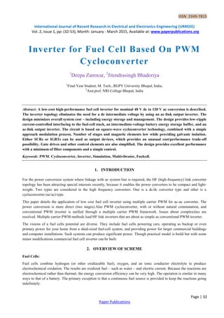
Inverter for Fuel Cell Based On PWM Cycloconverter
1. ISSN 2349-7815
International Journal of Recent Research in Electrical and Electronics Engineering (IJRREEE)
Vol. 2, Issue 1, pp: (32-53), Month: January - March 2015, Available at: www.paperpublications.org
Page | 32
Paper Publications
Inverter for Fuel Cell Based On PWM
Cycloconverter
1
Deepa Zamwar, 2
Jitendrasingh Bhadoriya
1
Final Year Student, M. Tech., RGPV University Bhopal, India,
2
Asst.prof. NRI College Bhopal, India
Abstract: A low-cost high-performance fuel cell inverter for nominal 48 V dc to 120 V ac conversion is described.
The inverter topology eliminates the need for a dc intermediate voltage by using an ac-link output inverter. The
design minimizes overall system cost – including energy storage and management. The design provides low-ripple
current-controlled interfacing to the fuel-cell stack, an intermediate-voltage battery energy storage buffer, and an
ac-link output inverter. The circuit is based on square-wave cycloconverter technology, combined with a simple
approach modulation process. Number of stages and magnetic elements low while providing galvanic isolation.
Either SCRs or IGBTs can be used as output devices, which provides an unusual cost/performance trade-off
possibility. Gate drives and other control elements are also simplified. The design provides excellent performance
with a minimum of filter components and a simple control.
Keywords: PWM, Cycloconverter, Inverter, Simulation, Multivibrator, Fuelcell.
1. INTRODUCTION
For the power conversion system where linkage with ac system line is required, the HF (high-frequency) link converter
topology has been attracting special interests recently, because it enables the power converters to be compact and light-
weight. Two types are considered in the high frequency converters. One is a dc/dc converter type and other is a
cycloconverter (ac/ac) type.
This paper details the application of low cost fuel cell inverter using multiple carrier PWM for ac-ac converter. The
power conversion is more direct (two stages).Also PWM cycloconverter, with or without natural commutation, and
conventional PWM inverter is unified through a multiple carrier PWM framework. Issues about complexities are
resolved. Multiple carrier PWM methods lead HF link inverters that are about as simple as conventional PWM inverter.
The visions of a fuel cells potential are diverse. They include fuel cells powering cars, operating as backup or even
primary power for your home from a shed-sized fuel-cell system, and providing power for larger commercial buildings
and computer installations. Such systems can produce significant power. Though practical model is build but with some
minor modifications commercial fuel cell inverter can be built.
2. OVERVIEW OF SCHEME
Fuel Cells:
Fuel cells combine hydrogen (or other oxidiazable fuel), oxygen, and an ionic conductor electrolyte to produce
electrochemical oxidation. The results are oxidized fuel – such as water – and electric current. Because the reactions are
electrochemical rather than thermal, the energy conversion efficiency can be very high. The operation is similar in many
ways to that of a battery. The primary exception is that a continuous fuel source is provided to keep the reactions going
indefinitely.
2. ISSN 2349-7815
International Journal of Recent Research in Electrical and Electronics Engineering (IJRREEE)
Vol. 2, Issue 1, pp: (32-53), Month: January - March 2015, Available at: www.paperpublications.org
Page | 33
Paper Publications
2.1.1 Chemistry and Characteristic of Fuel Cell :
Fig.1 provides a static current-voltage relationship for a prototype fuel cell. This particular curve is taken from a proton
exchange membrane (PEM) fuel cell model. PEM fuel cells use hydrogen as the fuel source and have an open circuit
voltage of 1.15 V per cell at 800
C and one atmosphere of pressure.
Under load, the voltage drops abruptly and is typically 0.6 V per cell or even less. It is important that the working voltage
be high enough to remain to the left of the ―knee‖ in the curve, which occurs at about 9A in Fig.1. A fuel cell stack with
64 cells in series, based on Fig.1, would have open-circuit voltage of 74 V and operating voltage of about 40 V. To
support the operation of the fuel cell stack, there will be a parasitic load for pumps, fans and other equipment typically of
the order of 1/6th
of rated load. In Fig.1, this balance of plant load implies an actual working voltage range of 0.5 to 0.8 V
per cell. The power processing system must be able to handle this range and withstand the open-circuit voltage during
startup conditions. In practice, a fuel cell stack with 64 cells would generate a working range of 32 to 52 V. There are
significant dynamic issues that must be addressed in any system. The dominate issues relate to fuel flow and transient
response.
Current (Amperes)
Fig. 1 Typical Fuel Cell Voltage-Current Characteristic
Fig.1 shows the behavior with 100% rated fuel flow in a flow-through type of system, but it does not reflect efficiency
considerations. For example, if the cell in Fig.1 operates at 2 A (about 25% of rated load) with 100% fuel flow, only a
small fraction of the fuel will actually participate in the electrochemical reaction. In a vented flow-through stack, the
remainder will be sent, unused, out the exhaust. Since direct recovery of hydrogen from the exhaust is difficult, wasted
fuel represents very low efficiency.
Other operating methods might use constant fuel pressure, in which case diffusion rates and oxygen supply limit the
performance. In a practical system, the fuel flow (or target is pressure) must be adjusted to match the reactant delivery
rate to the usage rate. A typical fuel utilization of at least 85% to avoid excessive waste.
2.2 Fuel Cell with Battery:
Fig.2 shows three of the family of curves that result when fuel flow is taken into account. In a flow-through PEM system,
for a given electrical load, the fuel flow should be adjusted to give the proper match. This causes two problems. First,
flow rates cannot be adjusted rapidly, and the internal chemistry must reach equilibrium before the cell can support
increased load. Second, if the electrical load increases too rapidly, it could drive the curve over Fig.1. Typical fuel cell
voltage-current characteristic the knee, exceeding maximum power transfer and overheating the fuel cell stack with extra
losses. The dynamics of fuel flow and diffusion of reactants are such that time constants associated with Fig.2 range from
several seconds for PEM technology to several minutes for some other fuel cell technologies—not useful for following
fast-changing electrical loads.
Voltage(volts)
3. ISSN 2349-7815
International Journal of Recent Research in Electrical and Electronics Engineering (IJRREEE)
Vol. 2, Issue 1, pp: (32-53), Month: January - March 2015, Available at: www.paperpublications.org
Page | 34
Paper Publications
Current (Amperes)
Fig.2 Voltage-Current Characteristics at Several Different Fuel Flow Levels
In any application with an uncontrolled electrical load, an energy buffer such as a separate battery will be needed to
permit instantaneous response to electrical load shifts while the fuel cell stack catches up.
However, based on Fig.2, it will not be feasible to simply add batteries in parallel with the stack. A battery – curve is
similar to a fuel cell and the operating point cannot be managed with a direct parallel connection, especially as fuel flow
rates change. In practice, this requires that a dual-port converter will be required to allow both a fuel cell and a battery to
be used independently. A battery will also require bidirectional energy flow to maintain charge over long intervals.
Convention dictates that fuel cells are intolerant to ripple current. Upon first examination, the physical structure of a fuel
cell is similar to that of an electrolytic capacitor, and fuel cells in general have significant internal capacitance. However,
since the electrochemistry is not perfectly efficient, internal losses limit the ability to withstand the extra losses caused by
ripple current. In addition, ripple current at relatively low frequencies will perturb the operating point and could drive
instantaneous operation beyond the knee of the characteristic curve. Thus a typical fuel cell is relatively intolerant to
current ripple at low frequencies of 120 Hz or less but is more forgiving of higher frequency ripple at several kilohertz or
more.
One challenge with a fuel cell is that the reaction rate is controlled in part by delivery of fuel. The fuel must be delivered
at least as fast as it is consumed, but fuel is wasted if the delivery rate is faster. In a practical system, this means that a
fuel cell looks like a battery with very slow dynamics: the time rates of change associated with sensors, pumps, fans, and
the system exhaust means that the fuel cell controller requires approximately one minute to respond to a command for
change, and about 90 s for initial start.
In an inverter system, the ac side load will have dynamics much faster than this, so an energy storage buffer will be
necessary. At a given fuel flow rate, a fuel cell has an optimum output current – that current will provide the highest
output power while minimizing losses and internal wear and tear. This behavior is somewhat similar to that of a solar cell,
although it is usual to operate a fuel cell at a current slightly below its maximum power output point to keep reliability
high. In the end, current optimization means that a precise average current control is needed for the fuel cell itself.
Fuel cells produces relatively low voltage – a fraction of a volt per cell – since the voltage is related to the
electrochemical potential of an H2 - O2 reaction. It is possible in principle to draw energy directly from an individual
cell. But the realities of device voltage drops and extreme currents mean that a single cell does not provide efficient
energy conversion. To alleviate this limitation and to achieve practical voltage levels, many cells must be connected in
series. This gives rise to the complete ―fuel cell stack.‖ In general, any voltage can be achieved by stacking cells in series,
but in the event of a single-cell failure or degradation, the entire stack will be affected. Thus there is an ―optimum
voltage‖ with some cells in series (but not too many). Although this optimum voltage has not been studied rigorously as
yet, conventional battery and solar cell practice suggests a level from 20 V to 60 V as a realistic value. Choose a nominal
48 V cell stack as the input to reflect this expectation.
System electrical safety is an issue. However, since it is possible to provide a safe enclosure for a unit, electrical safety is
somewhat secondary. Most standards practice accepts dc voltages under 60 V as a safe level not subject to special
protection requirements. On this basis, a 48 V fuel cell stack has important advantages – the open-circuit output when
Voltage(volts)
4. ISSN 2349-7815
International Journal of Recent Research in Electrical and Electronics Engineering (IJRREEE)
Vol. 2, Issue 1, pp: (32-53), Month: January - March 2015, Available at: www.paperpublications.org
Page | 35
Paper Publications
pumps and other necessary hardware are in place is unlikely to exceed 60 V. It is relatively easy to assemble a 48 V fuel
cell stack into a system that is safe enough for residential use.
A 48 V output is not enough to achieve a useful ac output voltage therefore a step-up function will be required. The only
way to achieve highly efficient energy conversion from 48 V dc to conventional 120/240 V ac is to use the techniques of
power electronics switching devices and energy storage elements to perform dc to ac conversion. However, the objective
of this project is not just to make power electronic circuits, but also to make them at low cost and to give them high
reliability.
2.3 Interfacing of Fuel Cell:
The source impedance characteristics shown in Fig.1 and 2 and the desire to operate the fuel cell at a specific ―fuel
utilization‖ level suggest current control as the appropriate interface with the fuel cell. The input current can be set at any
moment to the ideal value for the available fuel flow and the maximum current ripple is determined by design.
The current commanded from the fuel cell as well as the fuel flow rates can be adjusted to track the average output power
requirements of the inverter as the average electrical load changes. Batteries can be provided as a supplement to respond
to fast load variation.
The arrangement could be as simple as a boost converter cascaded with an inverter bridge. But what about the batteries?
In principle, they can be connected at the high-voltage dc bus. While a high-voltage battery is a simple approach, it raises
its own problems. Batteries in the range needed (more than 300 V) are difficult to manage. It is especially difficult to
maintain a tight charge balance [3], and it is unlikely that this could become a practical solution.
2.3.1 General Requirements:
The conversion topology must achieve several specific engineering objectives:
• Current control for the fuel cell must be supported. Precise control of current with minimum low frequency ripple is
needed.
• The fuel-cell current control must be decoupled from the rest of the system. That is, the current must be fully controlled
independent of the ac load.
• Energy storage must be provided to support decoupling between the fuel cell and the load, so rapid load changes do not
affect the fuel cell.
• A high-quality two-port sinusoidal output is needed.
2.3.2 Inverter with Step-up Transformer:
From a conceptual viewpoint, there are two general approaches that can be taken to this inverter problem:
Convert the energy from the fuel cell into ac form, and then step this up to produce the desired output. An example is
given in Fig3.
The trouble with this approach is that the transformer will have to be rated for the 50 Hz hence will require a bulky
mains-frequency transformer and will yield a heavy system with little opportunity for cost reduction. However, it offers
the advantage of galvanic isolation.
Fig.3 Direct Low-Voltage Inverter Followed by Transformer Step-up
5. ISSN 2349-7815
International Journal of Recent Research in Electrical and Electronics Engineering (IJRREEE)
Vol. 2, Issue 1, pp: (32-53), Month: January - March 2015, Available at: www.paperpublications.org
Page | 36
Paper Publications
2.3.3 DC–DC Converter Cascaded With Bridge Inverter:
Use a dc-dc conversion approach to step up the voltage (perhaps at high frequency), then use a conventional inverter to
produce the ac output. In concept, this approach can be treated as a conversion from dc to high-frequency ac, a
rectification to high-voltage dc and inversion to 50 Hz as in Fig.4 which involves a cascading of power conversion stages,
each of which adds loss. Eliminating the line frequency transformer reduces the size and weight but also eliminates
galvanic isolation.
Fig4 dc–dc Converter Cascaded with Bridge Inverter
In general terms, the conversion process can be treated as a cascade of a step-up from the fuel cell stack and a
conventional inverter, as in Fig.4. This is a boost converter cascaded with an inverter bridge. This arrangement does not
provide operational decoupling between the fuel cell and the inverter. In addition, the boost gain needed for the circuit of
Fig.2.4 is extreme. A gain of more than 7 from input to output must be achieved at high power with high efficiency. Such
extreme gains place severe requirements on the filter components, and seem unlikely to be practical.
2.3.4 Two Input Current Sourced Forward Converter:
The fuel cell and the batteries can be treated as two, more or less independent inputs to the boost converter – in the form
of a current-sourced forward converter. Fig.5 shows a current-sourced converter that can meet with the basic
requirements.
The general concept is that of a current-sourced forward converter, followed by a simple voltage-sourced inverter bridge.
Fig5 Two-Input Current-Sourced Forward Converter as the Basis for the Fuel Cell System
The concept in Fig.5 is viable, but has a number of challenges that prevent it from becoming a low-cost solution. First,
four significant magnetic elements are needed: two input side inductors, the forward converter transformer, and an
output-side filter inductor (inside the ―ac load‖ block). Second, the battery conversion portion must be bidirectional to
support both charge and discharge. The inverter bridge does not support dual output ports, although it permits either a
voltage-sourced inverter approach or a PWM inverter control.
An advantage of the approach is the redundancy of the fuel cell and batteries: operation can take place with just one
source connected. Another advantage is high efficiency: the batteries do not have to act as an intermediate energy source
if power can flow directly to the load. The most significant issue in configuration of Fig.5 is that of control decoupling. In
6. ISSN 2349-7815
International Journal of Recent Research in Electrical and Electronics Engineering (IJRREEE)
Vol. 2, Issue 1, pp: (32-53), Month: January - March 2015, Available at: www.paperpublications.org
Page | 37
Paper Publications
principle, the battery current can be chosen to exactly cancel dynamics of the inverter load to ensure constant current
drawn from the fuel cell. In practice it is hard to do this precisely.
Since the fuel cell supplies the forward converter directly, any change in the ac-side current will alter the fuel-cell current
unless control action is instant.
2.3.5 Forward Converter Driving Batteries and Inverter:
Fig.6 shows the other way of connecting the battery. This is the same as Fig.5, except that the battery has been moved to
the forward-converter output bus.
Fig.6 Forward Converter Driving Batteries and Inverter
Fig.6 is extremely simple and has considerable appeal, but from a system-level cost perspective it is flawed. The battery
bus will need to have a nominal value of about 340 V, which requires series connection of 28 lead-acid batteries. This
long series connection is not out of the question, but the charging of a long series string leads to imbalance problems .
Above approach is more expensive but commercialized. In either case, it would be preferable to minimize the imbalance
problem and avoid the cost of an extensive battery balancing network and wire harness.
2.3.6 Three Stage Converter Boost/Forward/ Inverter:
Fig.7 Three-Stage Converter: Boost/Forward/Inverter
Fig.7 shows a boost converter, followed by a voltage-sourced forward converter and inverter. A key advantage of this
topology is decoupling of control: the boost converter can act to maintain the desired current from the fuel cell,
independent of the forward converter action or of the inverter. There are two major troubles with this topology: First, the
extra diode in the boost converter reduces efficiency compared to the two-port converter approach (Fig. 5). Second,
addition of one conversion stage. Although the number of components has not changed much in terms of complexity
circuit of Fig.7 and Fig.5 are at par.
7. ISSN 2349-7815
International Journal of Recent Research in Electrical and Electronics Engineering (IJRREEE)
Vol. 2, Issue 1, pp: (32-53), Month: January - March 2015, Available at: www.paperpublications.org
Page | 38
Paper Publications
In Fig.7, there are three sets of controls: the initial boost converter control, the forward converter control, and the inverter
control. Furthermore, the power conversion blocks proceed from the current sourced fuel-cell input, to the voltage-
sourced battery bus.
This stack up of sources can be reduced, since at least one source is redundant.
2.3.7 Boost Converter Followed by ac Link Inverter and ac-ac Converter:
Reduction of redundancy will eliminate a portion of the control as well as the extra stage. The concept is embodied in a
high-frequency link arrangement, shown in Fig.8
The proposed design actually uses a third approach, based on ac link cycloconversion method. This eliminates the
rectification stage and performs inversion directly, simplifying the system.
Fig.8 Boost Converter, Followed by ac Link Inverter and ac-ac Converter for Output
This configuration is combination of boost converter, followed by ac link inverter and ac-ac converter for output. Forward
converter is replaced with a simple square-wave inverter which delivers a square-wave voltage to the output bus. The
inverter is replaced with an ac-ac converter to deliver the 50 Hz output. In this sense, the ac link approach leads to a
cycloconverter-type system, in which a square wave ac input is chopped to deliver the desired output.
Cycloconversion techniques are rarely used because of the control complexity, problems with devices, and poor output
harmonic characteristics. These limitations are not really fundamental: it is possible to produce the desired output
waveform directly from the ac link stage without the problems of a cycloconverter by using a new way to perform pulse-
width modulation (PWM) that actually produces a cycloconverter with a standard PWM output.
Block diagram for the scheme. Input is 24V battery/fuel cell with capacitor for filter. Inverter is of push pull configuration
with 1 KHZ frequency. Cycloconverter is having 50Hz frequency. Isolation is obtained from high frequency transformer.
Block Diagram
i. Control Block for Inverter:
Gate pulses are applied to switches of push pull inverter. Phase delay is introduced between pulses as Shown in Fig 9.
Gate pulses are in synchronization with 2 KHz ramp.
dc Input Inverter Isolation Cyclo
converter
Load
Control
Circuit
Control
Circuit
8. ISSN 2349-7815
International Journal of Recent Research in Electrical and Electronics Engineering (IJRREEE)
Vol. 2, Issue 1, pp: (32-53), Month: January - March 2015, Available at: www.paperpublications.org
Page | 39
Paper Publications
Fig.9 Control Block for Inverter
ii. Control Block for Cycloconverter:
For control block Multiple Carrier PWM scheme is used. In this high frequency carrier is used along with modulating
signal. Carrier could be triangle or ramp. Modulating signal is low frequency component. For multi carrier operation
instead of two carriers two modulating signals are taken which solve the purpose and is valid for single phase
cycloconverter. Carrier is 2 KHz ramp and modulating signal is 50Hz sine wave. Control is applied to cycloconverter side
while inverter gate pulses are synchronized with ramp at 1KHz.
Fig.10 Control Block for Cyclconverter
As shown in Fig.10 control module contains ramp generator of frequency 2KHz which also gives square wave of 1KHz
to be applied as control for forward converter i.e. inverter.
Sine wave obtained at 50Hz is modulating signal. For multiple carrier operation this sinusoidal waveform is phase shifted
by 1800
.
By comparing carrier and modulating signal PWM output is obtained. This PWM output is advanced or delayed for
achieving phase advanced and phase delayed trigger pulses respectively. Such pulse train is obtained using multivibrator
Delay
Circuit 1
Delay
Circuit 2
Gate 1
Gate 2
Synchronized
Control pulse
Square
Wave
Output
Inverter
Ramp Generator
Sine Wave
Generator
Phase Shift
Comparator 1
Comparator 2
Delay
Delay
Phase delayed
Pulse
Phase Advanced
Pulse
Gate Pulse For
Positive Converter
Gate Pulse For
Negative Converter
Driver
Driver
Cycloconverter2KHz
50Hz
1800
Load Current
Sensor
Logic Unit
9. ISSN 2349-7815
International Journal of Recent Research in Electrical and Electronics Engineering (IJRREEE)
Vol. 2, Issue 1, pp: (32-53), Month: January - March 2015, Available at: www.paperpublications.org
Page | 40
Paper Publications
The delayed waveform is blanked when the current is negative, while the advanced waveform is blanked when the current
is positive.
The two multivibrators are triggered from the rising edge of the respective comparator to produce a 15μs gate pulse train.
The upper multivibrator creates a phase-delayed gate pulse train to be used when load current is positive, while the lower
multivibrator creates a phase-advanced gate pulse train to be used when the load current is negative. Simple logic is used
with a current comparator to separate the positive and negative current conditions.
These trigger pulses are combined with another input obtained from current polarity detector. This current polarity
detector detects current direction across load.
Thus trigger pulses obtained are applied to positive and negative converter of cycloconverter through driver.
iii. Power Block:
Power block is described under two sections, as this consists of primary side and secondary side with isolation as shown
in Fig. The primary side, inverter operation is obtained through push-pull configuration while output is single phase
bridge consisting of 8 SCRs connected in antiparallel. RC snubber is designed for switches.
iv. Inverter:
As shown in Fig, inverter consists of push pull inverter which converters 24V dc to 96Vp-p, 1 KHz square wave. This
push pull inverter uses two MOSFETs as switches. Driver for MOSFET is obtained by transistorized circuit. Driver
signals are synchronized with 2 KHz ramp. Inverter switches at 1KHz. Filtering of dc voltage from battery is done
through capacitor.
Fig.11 Inverter
v. Cycloconverter:
Fig.12 shows schematic for ac-ac converter along with current polarity detection. Commutation of cycloconverter during
the zero crossing of load current is an important control issue, well understood from conventional ac cycloconverter
results. Ideally, the current polarity detection scheme in Fig.5 would use the ―fundamental current zero‖. While this
scheme results in ideal commutation with no cross-over distortion, it is known to be difficult to implement in practice.
Instead, Fig.5 uses a modification to the ―first current zero‖
Fig.12 Cycloconverter
dc Battery Push Pull Inverter
Synchronized
Gating Signals
Square Wave
24V 96Vp-p, 1 KHz
ac-ac Converter R-L Load
Current Polarity
Detection
10. ISSN 2349-7815
International Journal of Recent Research in Electrical and Electronics Engineering (IJRREEE)
Vol. 2, Issue 1, pp: (32-53), Month: January - March 2015, Available at: www.paperpublications.org
Page | 41
Paper Publications
As shown in block diagram secondary of power module consists of single phase ac-ac converter with 8 SCRs along with
4 RC snubbers. Load connected is RL and switching is controlled from trigger pulses obtained from control module
whose feedback is from current polarity detector, which senses the load fed from cycloconverter. Isolation between
source and load is obtained using HF transformer. This transformer uses ferrite core to achieve high frequency square
wave transfer.
3. DESIGN OF INVERTER CONTROL BLOCK
Synchronized square pulse is obtained which is phase shifted and delayed before applying to switches.
i. Design of Synchronized Square Pulse:
Synchronized square pulse is achieved from ramp generator as shown in fig. D flip flop IC4013 is used with reset on ON
facility. Clock is given through non-inverting buffer consisting of CE amplifier with BC 546. Diode IN4148 is used as
edge detector and for bypassing negative cycle.
IC4013 is used to generate square wave of 1 KHz synchronized with 2 KHz ramp. Clock frequency is also 2 KHz. The
CD4013B dual D-type flip-flop is used.
Q
Q
SET
CLR
D
From Ramp
Generator
10kΩ 10kΩ
10kΩ
10kΩ
10kΩ
10kΩ
4148
+12V
1KHz Square
Pulse
+12V +12V
4148
.1μF
Fig.13 Synchronized Square Pulse
ii. Design of Gate Pulse:
The 50% duty cycle for gate pulses still support pulse transformer coupling, retaining the simplicity of the gate drive
isolation. The PWM cycloconverter process scales directly to higher switching speeds possible with these devices. NAND
gate IC 4093 is used for inversion in gate pulse. Delay is obtained using standard RC circuit.
R = 10 K Ω
C = 0.01 μF
R*C = 0.1ms
1KHz Square
Pulse
10KΩ
10KΩ
.01μF
.01μF
IC4093
Fig.14 Gate Pulses for Inverter
11. ISSN 2349-7815
International Journal of Recent Research in Electrical and Electronics Engineering (IJRREEE)
Vol. 2, Issue 1, pp: (32-53), Month: January - March 2015, Available at: www.paperpublications.org
Page | 42
Paper Publications
iii. Design of Ramp Generator :
Ramp Generator is achieved from triangular wave generator by inserting a variable dc voltage into the non-inverting
terminal of the integrator A2 as shown in Fig.6. A duty cycle less than 50% causes output of A2 to be a ramp. When R4
wiper is moved toward –VEE, the rise time of ramp becomes longer than fall time. Also frequency of ramp is adjusted
with R4. Amplitude of output is independent of R4.
Design is done for 7Vp-p, 2 KHz positive going ramp using op-amp [13]
fo = 2 KHz
R2/ R3 = Vp-p / 2*Vsat
Let Vp-p = 7V
R2 = 10 KHz
Vsat = 12V
R3 = 34.28 KΩ
Choose R3 = 22K+10Kpot
fo = R3/4 R1*C1*R2
R1*C1 = 0.4ms
Let C1 = 0.47μF
R1 = 851 Ω
Let R1 = 1KΩ
Where fo ---------Output frequency in Hz.
Vp-p--------- peak to peak output voltage
As shown in fig , buffering and amplification is obtained from 3A op-amp. 47 KΩ for high input impedance and
combination of 6 KΩ and 1 KΩ resistance for dc level shift hence obtaining swing of ramp across zero. Final value
adjusted to 3 Vp-p and 2.5 KHz frequency. Quad op-amp IC348 is used in circuit. LM348 is chosen for ramp generation
0.47μF
1KΩ
+12V
-12V
2.2KΩ
2.2KΩ
20KΩ
10KΩ22KΩ
10KΩ
6KΩ
1KΩ
47KΩ
+12V
-12V
6.2V
6.2V
-
+
-
+
+
-
10KΩ
Ramp Output
To Inverter
Control Block
A1
A2 A3
LM 348
Fig.15 Ramp Generator
12. ISSN 2349-7815
International Journal of Recent Research in Electrical and Electronics Engineering (IJRREEE)
Vol. 2, Issue 1, pp: (32-53), Month: January - March 2015, Available at: www.paperpublications.org
Page | 43
Paper Publications
a. Design of Sine Wave Generator :
Sine wave is obtained using bridge oscillator [13] as shown in Fig. Designing is done at 12Vp-p, 50 Hz frequency.
fo = 0.159/Rc
R*C =3.18ms
Let C = 0.47 μF
R = 6.7 KΩ
Gain Rf ‗[/ R1 = 2
Let R1=5.'1 KΩ
R1=5.1 KΩ
Rf = 10 KΩ
Rf = 10 KΩ pot
2 Vp-p is achieved using potential divider as shown in Fig. 9. Buffer is also connected. This sine wave is further inverted
using op-amp as inverting amplifier. Gain for this op-amp is set as 1 with combination of 10 K and 9.1 K and 2K pot.
0.47μF
1KΩ
1KΩ
6KΩ
6.8K
Ω
10KΩ
5.1KΩ
10KΩ
10KΩ
+12V
+12V
+
-
-
+
-
+
Sine Output
LM 324
0.47μ
F
9.1KΩ 2KΩ
6.8KΩ
+
-
A
B
C
D
TO Comparator 1
TO Comparator 2
Fig.16
b. Design of Comparator:
For obtaining PWM comparison is done between ramp and sine using high speed voltage comparator dual comparator
LM319. Modulation index is set to 0.66.
+12V
1KΩ
10KΩ
1KΩ
-
+
-
+
10KΩ
10KΩ
+12V
LM319
2KHz Ramp
Phase Shifted Sine Wave
50Hz Sine
Wave
PWM Output 2
PWM Output 1
Fig.17 PWM Generator
13. ISSN 2349-7815
International Journal of Recent Research in Electrical and Electronics Engineering (IJRREEE)
Vol. 2, Issue 1, pp: (32-53), Month: January - March 2015, Available at: www.paperpublications.org
Page | 44
Paper Publications
c. Design of Multivibrator:
The MC14538B is a dual, retriggerable, resettable monostable multivibrator. It may be triggered from either edge of an
input pulse, and produces an accurate output pulse over a wide range of widths, the duration and accuracy.
1.5KΩ
0.01μF
1.5KΩ
0.01μF
10KΩ
0.1μF
12V
12V12V12V
PWM
Input 1
PWM
Input 2
Delay
Output 1
Delay
Output 2
IC
4538
Fig.18 Delay Output
Of which are determined by the external timing components, CX and RX.
For 15μs delay value of CX and RX are chosen as 0.01μF and 1.5KΩ respectively.
d. Design of Logical Unit:
Design for Delayed and Advanced circuit:
NOR (IC4001) logic is used for obtaining phase advanced and phase delayed trigger pulses.
Phase Delayed
Pulses
Phase Advanced
Pulses
Current Feedback
10KΩ
+
-
12V
LM311
MC14001
PWM Input
PWM Input
Fig.19.Circuit of Logical Unit
Design for Feedback Network - Single comparator is required for comparing feedback current obtained from load and
PWM output obtained. Input is connected in differential mode as shown in Fig.19.
Both the inputs and the outputs of the LM311 can be isolated from system ground, and the output can drive loads referred
to ground, the positive supply or the negative supply.
14. ISSN 2349-7815
International Journal of Recent Research in Electrical and Electronics Engineering (IJRREEE)
Vol. 2, Issue 1, pp: (32-53), Month: January - March 2015, Available at: www.paperpublications.org
Page | 45
Paper Publications
e. Design of Driver:
The driver circuit of cycloconverter consists of Pulse Transformer and transistors along with diode and resistances. As
cycloconverter is having SCRs as switches only edges are required for trigger. To obtain voltage level transistor is used as
an amplifier. Standard configuration is applied for achieving trigger pulses as shown in Fig. Transistor BD139 is used as
driver and BC546 as buffer. Such unit is used for each SCR.
1kΩ
10kΩ
1kΩ
1kΩ
10kΩ
1kΩ
100Ω4007
4007
PT
BD139
BC546
12V
12V
Trigger Pulse
Trigger to SCR
Fig.20 Driver of SCR
4. POWER CIRCUIT DESIGN
i. Design of Inverter:
Inverter is designed using push pull configurations and calculations are done as per requirement. Gate pulse is obtained
from circuit shown in previous chapter. MOSFET is chosen for high frequency switching. Two 12V batteries are
connected in series for obtaining 24V as fuel cell is not available. Batteries used are of standard company with 1A-Hr
rating.
ii. Design of Push Pull Inverter:
24 Vdc is converted into square wave of 1 KHz frequency and amplitude of 48V at primary of output transformer using
push-pull inverter. This is achieved by circuit shown in Fig.21.
Care is taken that switch has low saturation voltage and breakdown voltage is two to three times the supply voltage.
Isolation is obtained through HF transformer which is described in the next section. Capacitor value 220μF/63V is
connected across 24V battery for filtering.
Edc = 24V
Eout = 220V
Po = 200W
Io = 1A
Let η = 70%
Pin = 285W
Iin = Pin/Edc
=6A
15. ISSN 2349-7815
International Journal of Recent Research in Electrical and Electronics Engineering (IJRREEE)
Vol. 2, Issue 1, pp: (32-53), Month: January - March 2015, Available at: www.paperpublications.org
Page | 46
Paper Publications
24V
220μF/63V
47kΩ
47kΩ
Gate Pulse
Gate Pulse
HF Transformer
1:2
200V Square
Wave
Fig.21 Push Pull Inverter
IRF540N Power MOSFET is used.
iii. Design of MOSFET Snubber:
fs = 1KHz
Edc = 24V
iL=6A
Let L = 25 μH
tf = 40x10-9 s
where
tf is fall time
fs switching frequency
C = iL*tf / Edc
= 6 * tf / 24
C = 0.01μF
L = Edc*tr / iL
tr = 6.25 μs
where tr is rise time
di/dt = iL/tr
= 0.96A/μs
Switch ON
di/dt = 0.24 A/μs
R = √(4*L/C)
R = 100 Ω
Hence values for snubber are chosen as 100 Ω,1W and 0.01μF/250V.
16. ISSN 2349-7815
International Journal of Recent Research in Electrical and Electronics Engineering (IJRREEE)
Vol. 2, Issue 1, pp: (32-53), Month: January - March 2015, Available at: www.paperpublications.org
Page | 47
Paper Publications
iv. Design of Transformer:
Ferrite core is used for transformer as operation frequency is 1KHz and input is Square Wave. Core is selected as per
power requirement.
Edc = 24V
Eout = 220V
Po = 200W
Io = 1A
Let η = 70%
Pin = 285W
Iin = Pin/Edc
= 6A
As per calculations core required was EE-65x33x28 but due to its non-availability core used is EE-55x27x21 type 5s
Area = 20mmx17mm
N = Eout/Edc
= 5
Eout ×105
Ns = ---------------
4×Bmax×A×f
Bmax = 4800G
Br = 1800G
Hc = 11.9A/m
Let Bmax = 3150G
Calculating from above equation
Ns = 462
Np = 93
As push pull type hence each primary winding will have 93 turns each.
Maximum current rating is reduced due to core used.
v. Design of ac-ac Converter :
Secondary of high frequency transformer drives bridge of SCRs connected in anti-parallel and bridge is working as
cycloconverter. SCRs are triggered from pulse transformer.
vi. Design of Cycloconverter:
As explained in a previous section current is approximately 1A hence SCR rating is chosen accordingly. As shown in Fig.
eight SCRs are connected in anti-parallel to achieve ac-ac converter configuration. T1-T4 comprise of positive converter
while T5-T8 comprise of negative converter.
SCR used is TYN612 having following features:
IT (RMS) -RMS on-state current (180° conduction angle) is 12 A
17. ISSN 2349-7815
International Journal of Recent Research in Electrical and Electronics Engineering (IJRREEE)
Vol. 2, Issue 1, pp: (32-53), Month: January - March 2015, Available at: www.paperpublications.org
Page | 48
Paper Publications
VDRM/VRRM Repetitive peak off-state forward voltage is 600 to 1000 V
IGT Gate Current is 0. 2 to 15 mA
T1
200mH 26Ω CT
T3
T2T4
T5
T6
T8
T7
Load
Fig.22 Cycloconverter
Load is inductive load of 200 mH with self resistance of value 26 Ω.
Current transformer is connected to obtain current polarity for feedback. Construction of current transformer is done to
achieve ratio of 1:300.
N1I1 = N2I2
2x1A = 600xI2
I2 = 3mA
V = IR
= 3x10-3 x 220 Ω,
= 660mV
Secondary of current transformer is connected with resistance R(220Ω) whose value is chosen such that voltage obtained
across R is enough as input to comparator LM311 connected in triggering circuit for selection of positive and negative
converter.
vii. Design of Thyristor Snubber:
Let dv/dt = 400 V/μs
L = 25 μH
dv/dt = E*R/L
E = 100V
Where E is secondary voltage peak.
R = 100 Ω
R+R1 = 2√L/C
Let R1 = 0.02 Ω
C = 0.01 μF
Hence value for snubber chosen is 100 Ω, 1W and 0.01μF/250V.
For heat sink PHS-16 is used as power dissipation is very low.
18. ISSN 2349-7815
International Journal of Recent Research in Electrical and Electronics Engineering (IJRREEE)
Vol. 2, Issue 1, pp: (32-53), Month: January - March 2015, Available at: www.paperpublications.org
Page | 49
Paper Publications
5. SIMULATION & RESULTS
Simulations are done to obtain different gate pulses for different combinations described in table These gate pulses are
combined with square wave as HF link voltage to obtain output voltage. (Refer Table 1)
Table 1
Scenario
Carrier
Type
Phase
Shifter
1
Phase
Shifter
2
Phase
Shifter
3
Combining
Method
Gate
Drive
Signal
Type
Output PWM
Equivalent
1 Triangle 0 0 180° Add 2-Level
Ramp PWM at
double fswitch'
2 Triangle 0 180° 0 Subtract 3-Level Triangle PWM
3 Ramp 0 0 0 Add 2-Level Triangle PWM
4 Ramp 180° 0 0 Subtract 3-Level
Ramp PWM at
double fswitch'
Fig.23 Simulation Block for scenario 1
19. ISSN 2349-7815
International Journal of Recent Research in Electrical and Electronics Engineering (IJRREEE)
Vol. 2, Issue 1, pp: (32-53), Month: January - March 2015, Available at: www.paperpublications.org
Page | 50
Paper Publications
Fig.24 Simulation Result for scenario 1
Fig.25 Simulation Block scenario 2
Fig.26 Simulation Result for scenario 2
20. ISSN 2349-7815
International Journal of Recent Research in Electrical and Electronics Engineering (IJRREEE)
Vol. 2, Issue 1, pp: (32-53), Month: January - March 2015, Available at: www.paperpublications.org
Page | 51
Paper Publications
Fig.27 Simulation Block for scenario 3
Fig.28 Simulation Result for scenario 3
Fig.29 Simulation Block for scenario 4
Transport
Delay
Switch
Sine Wave1
Sine Wave
Signal
Generator1
Signal
Generator
Scope1
Saturation2
Saturation1
Saturation
>=
Relational
Operator1
>=
Relational
Operator
OR
Logical
Operator
-1
Gain1
-1
Gain
5
Constant1
-5
Constant
Transport
Delay
Switch
Sine Wave
Signal
Generator1
Signal
Generator
Scope1
Saturation2
Saturation1
Saturation
>=
Relational
Operator1
>=
Relational
Operator
5
Constant1
-5
Constant
21. ISSN 2349-7815
International Journal of Recent Research in Electrical and Electronics Engineering (IJRREEE)
Vol. 2, Issue 1, pp: (32-53), Month: January - March 2015, Available at: www.paperpublications.org
Page | 52
Paper Publications
Fig.30 Simulation result for scenario 4
6. CONCLUSION
The scheme suggested shows that the number of stages can be reduced, leading to a HF-link conversion approach. The
reduction came from recognizing redundancy in the power processing. Without a dc link bus, rectifiers and filter
components along with their associated losses are eliminated. Applying the techniques of multiple carrier PWM
cycloconversion results are exactly identical to conventional PWM techniques.
The combination of a current-controlled input, adjust the average power demand from a fuel cell, battery buffer, and
PWM cycloconverter, provides a reduced parts-count solution compared to conventional boost-forward-inverter cascade
topology. The combined converter isolates the fuel cell from its load both electrically and dynamically while reducing
parts count and therefore reduces costs.
REFERENCES
[1] M. Koyama, ―High frequency link dc/ac converter with PWM cycloconverter for UPS,‖ in Proc. IPEC‘90 Conf.,
Tokyo, Japan, 1990, pp. 748–754.
[2] T. Kawabata, K. Honjo, N. Sashida, K. Sanada, and M. Koyama, ―High frequency link dc/ac converter with PWM
cycloconverter,‖in Proc. IEEE Industry Applications Soc. Annu. Meeting, 1990, pp. 1119–1124.
[3] T. Aoki, K. Yotsumoto, S. Muroyama, and Y. Kenmochi, ―A new uninterruptible power supply with a
bidirectional cycloconverter,‖ in Proc. IEEE Int. Telecommunications Energy Conf., 1990, pp. 424–429.
[4] J. Kassakian, M. Schlecht, and G. Verghese, Principles of Power Electronics. Reading, MA: Addison-Wesley,
1991, pp. 186–187.
[5] N. H. Kutkut, D. M. Divan, D. W. Novotny, ―Charge equalization of series connected battery strings,‖ IEEE
Trans. Industry Applications, vol. 31, no. 3, pp. 562-568, May 1994.
[6] R. D. Brost, ―Performance of valve-regulated lead-acid batteries in EV1 extended series strings,‖ in Proc. 13th
Annual Battery Conf. On Applications and Advances, 1998, pp. 25-29.
[7] S. West and P. T. Krein, ―Equalization of valve-regulated lead-acid batteries: issues and life test results,‖ in Proc.
IEEE Int. Telecommunications Energy Conf., 2000, pp. 439–446.
[8] S. West, P. T. Krein, "Equalization of valve-regulated lead-acid batteries: issues and life test results," in Proc.
IEEE Int'l Telecommunications Energy Conf., 2000, pp. 439-446.
22. ISSN 2349-7815
International Journal of Recent Research in Electrical and Electronics Engineering (IJRREEE)
Vol. 2, Issue 1, pp: (32-53), Month: January - March 2015, Available at: www.paperpublications.org
Page | 53
Paper Publications
[9] P. T. Krein, ―Tricks of the Trade: Simple Solar Cell Models,‖ IEEE Power Electronics Society Newsletter, April
2001.
[10] Fuel cells, IEEE Spectrum. June 2001.
[11] S. Haykin, Communication Systems, 4th ed. New York: Wiley, 2001, p. 211
[12] B. R. Pelly, Thyrister Phase Controlled Converters and Cycloconverters. New York: Wiley-Interscience, 1971.
[13] Op-Amps and Linear Integrated Circuits by Ramamkant A.Gayakwad.