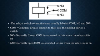
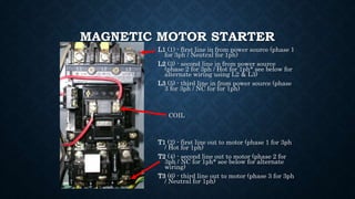
A relay is an electrically operated switch that is activated by a current or signal in one circuit to open or close another circuit. Relays work by using a magnetic field created by a coil to attract a lever and change the switch contacts. Relays have applications in controlling electric motors, automatic stabilizers, and performing arithmetic operations in computers. A miniature circuit breaker is an electromagnetic device that automatically opens a circuit when the current passes a set limit, to protect from overloads or faults. Relays are used to sense faults and send a signal to circuit breakers to isolate the circuit. Contactors are high current relays used to switch loads like motors, and magnetic motor starters include contactors and overloads for protection.
A relay is an electrically operated switch. It consists of a set of input terminals for a single or multiple control signals, and a set of operating contact terminals. The switch may have any number of contacts in multiple contact forms, such as making contacts, break contacts, or combinations thereof.
FUNDAMENTALS OF POWER SYSTEM PROTECTION
FUNDAMENTALS OF POWER SYSTEM PROTECTIONFUNDAMENTALS OF POWER SYSTEM PROTECTIONFUNDAMENTALS OF POWER SYSTEM PROTECTIONFUNDAMENTALS OF POWER SYSTEM PROTECTIONFUNDAMENTALS OF POWER SYSTEM PROTECTIONFUNDAMENTALS OF POWER SYSTEM PROTECTIONFUNDAMENTALS OF POWER SYSTEM PROTECTIONFUNDAMENTALS OF POWER SYSTEM PROTECTIONFUNDAMENTALS OF POWER SYSTEM PROTECTIONFUNDAMENTALS OF POWER SYSTEM PROTECTIONFUNDAMENTALS OF POWER SYSTEM PROTECTIONFUNDAMENTALS OF POWER SYSTEM PROTECTIONFUNDAMENTALS OF POWER SYSTEM PROTECTIONFUNDAMENTALS OF POWER SYSTEM PROTECTIONFUNDAMENTALS OF POWER SYSTEM PROTECTIONFUNDAMENTALS OF POWER SYSTEM PROTECTIONFUNDAMENTALS OF POWER SYSTEM PROTECTIONFUNDAMENTALS OF POWER SYSTEM PROTECTIONFUNDAMENTALS OF POWER SYSTEM PROTECTIONFUNDAMENTALS OF POWER SYSTEM PROTECTIONFUNDAMENTALS OF POWER SYSTEM PROTECTIONFUNDAMENTALS OF POWER SYSTEM PROTECTIONFUNDAMENTALS OF POWER SYSTEM PROTECTIONFUNDAMENTALS OF POWER SYSTEM PROTECTIONFUNDAMENTALS OF POWER SYSTEM PROTECTIONFUNDAMENTALS OF POWER SYSTEM PROTECTIONFUNDAMENTALS OF POWER SYSTEM PROTECTIONFUNDAMENTALS OF POWER SYSTEM PROTECTIONFUNDAMENTALS OF POWER SYSTEM PROTECTIONFUNDAMENTALS OF POWER SYSTEM PROTECTIONFUNDAMENTALS OF POWER SYSTEM PROTECTIONFUNDAMENTALS OF POWER SYSTEM PROTECTIONFUNDAMENTALS OF POWER SYSTEM PROTECTIONFUNDAMENTALS OF POWER SYSTEM PROTECTIONFUNDAMENTALS OF POWER SYSTEM PROTECTIONFUNDAMENTALS OF POWER SYSTEM PROTECTIONFUNDAMENTALS OF POWER SYSTEM PROTECTIONFUNDAMENTALS OF POWER SYSTEM PROTECTIONFUNDAMENTALS OF POWER SYSTEM PROTECTIONFUNDAMENTALS OF POWER SYSTEM PROTECTIONFUNDAMENTALS OF POWER SYSTEM PROTECTIONFUNDAMENTALS OF POWER SYSTEM PROTECTIONFUNDAMENTALS OF POWER SYSTEM PROTECTIONFUNDAMENTALS OF POWER SYSTEM PROTECTIONFUNDAMENTALS OF POWER SYSTEM PROTECTIONFUNDAMENTALS OF POWER SYSTEM PROTECTIONFUNDAMENTALS OF POWER SYSTEM PROTECTION
Introduction of SCADA, Architecture of SCADA, Software and hardware architecture, Components of a SCADA system, Functions of SCADA, Alarms and events, alarm logging, comparision between scada and DCS
PLC Ladder Diagram basics, with two solved examples
For more information go to
http://shrutizpresentations.blogspot.in/2014/04/plc-ladder-diagram-basics.html
The electricity supply industry is undergoing a profound transformation worldwide. Market forces, scarcer natural resources, and an ever-increasing demand for electricity are some of the drivers responsible for such unprecedented change. Against this background of rapid evolution, the expansion programs of many utilities are being thwarted by a variety of well-founded, environment, land-use, and regulatory pressures that prevent the licensing and building of new transmission lines and electricity generating plants.
PLCC system uses the same High Voltage transmission line connecting
two sub-stations for telecommunication purpose too.
PLCC is used in all power utilities as a primary communication service to transmit speech, telemetry and protection tripping commands. This is economic and reliable for inter grid message transfer as well as low bit rate RTU signals.
The voice/data are mixed with radio frequency carrier (40-500kHz), amplified to a level of 10-80W RF power and injected in to high voltage power line using a suitable coupling capacitor. The power line as a rigid long conductor parallel to ground, guides the carrier waves to travel along the transmission line. Point to point communication takes place between two SSB transceivers at both ends.
A switchgear or electrical switchgear is a generic term which includes all the switching devices associated with mainly power system protection. It also includes all devices associated with control, metering and regulating of electrical power system. Assembly of such devices in a logical manner forms a switchgear. This is the very basic definition of switchgear.
⋗To get more with details
https://www.youtube.com/channel/UC2SvKI7eepP241VLoui1D5A
Types of Relay - Which One Should You UseWagoIndia
Looking for a reliable and easy-to-use relay module? Click here to explore range of WAGO relay and optocoupler modules for your application. Visit us at https://www.wago.com/in/interface-electronic/discover-relays-optocouplers
NO1 Uk best vashikaran specialist in delhi vashikaran baba near me online vas...Amil Baba Dawood bangali
Contact with Dawood Bhai Just call on +92322-6382012 and we'll help you. We'll solve all your problems within 12 to 24 hours and with 101% guarantee and with astrology systematic. If you want to take any personal or professional advice then also you can call us on +92322-6382012 , ONLINE LOVE PROBLEM & Other all types of Daily Life Problem's.Then CALL or WHATSAPP us on +92322-6382012 and Get all these problems solutions here by Amil Baba DAWOOD BANGALI
#vashikaranspecialist #astrologer #palmistry #amliyaat #taweez #manpasandshadi #horoscope #spiritual #lovelife #lovespell #marriagespell#aamilbabainpakistan #amilbabainkarachi #powerfullblackmagicspell #kalajadumantarspecialist #realamilbaba #AmilbabainPakistan #astrologerincanada #astrologerindubai #lovespellsmaster #kalajaduspecialist #lovespellsthatwork #aamilbabainlahore#blackmagicformarriage #aamilbaba #kalajadu #kalailam #taweez #wazifaexpert #jadumantar #vashikaranspecialist #astrologer #palmistry #amliyaat #taweez #manpasandshadi #horoscope #spiritual #lovelife #lovespell #marriagespell#aamilbabainpakistan #amilbabainkarachi #powerfullblackmagicspell #kalajadumantarspecialist #realamilbaba #AmilbabainPakistan #astrologerincanada #astrologerindubai #lovespellsmaster #kalajaduspecialist #lovespellsthatwork #aamilbabainlahore #blackmagicforlove #blackmagicformarriage #aamilbaba #kalajadu #kalailam #taweez #wazifaexpert #jadumantar #vashikaranspecialist #astrologer #palmistry #amliyaat #taweez #manpasandshadi #horoscope #spiritual #lovelife #lovespell #marriagespell#aamilbabainpakistan #amilbabainkarachi #powerfullblackmagicspell #kalajadumantarspecialist #realamilbaba #AmilbabainPakistan #astrologerincanada #astrologerindubai #lovespellsmaster #kalajaduspecialist #lovespellsthatwork #aamilbabainlahore #Amilbabainuk #amilbabainspain #amilbabaindubai #Amilbabainnorway #amilbabainkrachi #amilbabainlahore #amilbabaingujranwalan #amilbabainislamabad
Water scarcity is the lack of fresh water resources to meet the standard water demand. There are two type of water scarcity. One is physical. The other is economic water scarcity.
Final project report on grocery store management system..pdfKamal Acharya
In today’s fast-changing business environment, it’s extremely important to be able to respond to client needs in the most effective and timely manner. If your customers wish to see your business online and have instant access to your products or services.
Online Grocery Store is an e-commerce website, which retails various grocery products. This project allows viewing various products available enables registered users to purchase desired products instantly using Paytm, UPI payment processor (Instant Pay) and also can place order by using Cash on Delivery (Pay Later) option. This project provides an easy access to Administrators and Managers to view orders placed using Pay Later and Instant Pay options.
In order to develop an e-commerce website, a number of Technologies must be studied and understood. These include multi-tiered architecture, server and client-side scripting techniques, implementation technologies, programming language (such as PHP, HTML, CSS, JavaScript) and MySQL relational databases. This is a project with the objective to develop a basic website where a consumer is provided with a shopping cart website and also to know about the technologies used to develop such a website.
This document will discuss each of the underlying technologies to create and implement an e- commerce website.
CFD Simulation of By-pass Flow in a HRSG module by R&R Consult.pptxR&R Consult
CFD analysis is incredibly effective at solving mysteries and improving the performance of complex systems!
Here's a great example: At a large natural gas-fired power plant, where they use waste heat to generate steam and energy, they were puzzled that their boiler wasn't producing as much steam as expected.
R&R and Tetra Engineering Group Inc. were asked to solve the issue with reduced steam production.
An inspection had shown that a significant amount of hot flue gas was bypassing the boiler tubes, where the heat was supposed to be transferred.
R&R Consult conducted a CFD analysis, which revealed that 6.3% of the flue gas was bypassing the boiler tubes without transferring heat. The analysis also showed that the flue gas was instead being directed along the sides of the boiler and between the modules that were supposed to capture the heat. This was the cause of the reduced performance.
Based on our results, Tetra Engineering installed covering plates to reduce the bypass flow. This improved the boiler's performance and increased electricity production.
It is always satisfying when we can help solve complex challenges like this. Do your systems also need a check-up or optimization? Give us a call!
Work done in cooperation with James Malloy and David Moelling from Tetra Engineering.
More examples of our work https://www.r-r-consult.dk/en/cases-en/
Hierarchical Digital Twin of a Naval Power SystemKerry Sado
A hierarchical digital twin of a Naval DC power system has been developed and experimentally verified. Similar to other state-of-the-art digital twins, this technology creates a digital replica of the physical system executed in real-time or faster, which can modify hardware controls. However, its advantage stems from distributing computational efforts by utilizing a hierarchical structure composed of lower-level digital twin blocks and a higher-level system digital twin. Each digital twin block is associated with a physical subsystem of the hardware and communicates with a singular system digital twin, which creates a system-level response. By extracting information from each level of the hierarchy, power system controls of the hardware were reconfigured autonomously. This hierarchical digital twin development offers several advantages over other digital twins, particularly in the field of naval power systems. The hierarchical structure allows for greater computational efficiency and scalability while the ability to autonomously reconfigure hardware controls offers increased flexibility and responsiveness. The hierarchical decomposition and models utilized were well aligned with the physical twin, as indicated by the maximum deviations between the developed digital twin hierarchy and the hardware.
Industrial Training at Shahjalal Fertilizer Company Limited (SFCL)MdTanvirMahtab2
This presentation is about the working procedure of Shahjalal Fertilizer Company Limited (SFCL). A Govt. owned Company of Bangladesh Chemical Industries Corporation under Ministry of Industries.
Sachpazis:Terzaghi Bearing Capacity Estimation in simple terms with Calculati...Dr.Costas Sachpazis
Terzaghi's soil bearing capacity theory, developed by Karl Terzaghi, is a fundamental principle in geotechnical engineering used to determine the bearing capacity of shallow foundations. This theory provides a method to calculate the ultimate bearing capacity of soil, which is the maximum load per unit area that the soil can support without undergoing shear failure. The Calculation HTML Code included.
2. RELAY
• An electrical device, typically incorporating an electromagnet, which is
activated by a current or signal in one circuit to open or close another
circuit.
• A relay is an electrically operated switch.
3. WORKING OF RELAY
• Current flowing through the coil of the relay creates a magnetic field which attracts
a lever and changes the switch contacts.
• The coil current can be on or off so relays have two switch positions and they are
double throw (changeover) switches.
4. • The relay’s switch connections are usually labeled COM, NC and NO:
• COM =Common, always connect to this, it is the moving part of a
switch
• NC= Normally Closed,COM is connected to this when the relay coil is
off
• NO= Normally open,COM is connected to this when the relay coil is on
5. RELAY OPERATION OFF STATE
• Drawn in natural state.
• Where the voltage present when load side is open
• In this relay’s natural state it is in the normally open state.
• When the coil is non-energized the contacts are open.
6. RELAY OPERATION ON STATE
• When there is current through the coil of wire on the control side a magnetic field is
produced.
• This magnetic field closed the contacts on the load side.
• In this relay’s natural state it is in the normally closed state.
• When the coil is energized the contacts closed.
7. APPLICATIONS OF RELAY:
• Relays are not only used in the large electrical circuits but also used in the computer
circuits in order to perform the arithmetic and mathematical operations in it.
• Used to control the electric motor switches. To turn ON an electric motor we need 230V
AC supply but in few cases/applications, there may be a situation to switch ON the
motor with a DC supply voltage. In those cases, a relay can be used.
• Automatic stabilizers are one of its applications where a relay is used. When the supply
voltage is other than the rated voltage, set of relays sense the voltage variations and
controls the load circuit with the help of circuit breakers.
8. RELAY RATINGS AND LIMITS
• Relays often have two ratings: AC and DC. These rating indicate how much power can
be switched through the relays.
• For instance, a 5 Amp relay rated at 125VAC can also switch 2.5 Amps at 250VAC.
Similarly, a 5 Amp relay rated at 24VDC can switch 2.5 Amps at 48VDC, or even 10
Amps at 12VDC.
9. MINIATURE CIRCUIT BREAKER
• A miniature circuit breaker is an electromagnetic device that carries a complete molded
insulating material. The primary function of this device is to switch the circuit. This means
to automatically open the circuit (which has been connected to it) when the current
passing through the circuit goes beyond a set value or limit. The device can be manually
switched ON or OFF just like normal switches whenever necessary.
• A miniature circuit breaker (MCB) automatically switches off the electrical circuit during an
abnormal condition of the network means in overload condition as well as faulty
condition.
10. RELAY AND MINIATURE CIRCUIT BREAKER
• The Relay is a switching device which gives a signal to the circuit breaker as
soon as the fault occurs in the power system. Circuit breaker breaks the
circuit automatically when receives the signal from the relay.
• The Relay is a switching and sensing device, but the Circuit breaker is an
isolating or disconnecting device.
• Relays operate on low power input voltage. The Circuit breaker is an
automatic on load device.
• The Relay is used to control or select one among many circuits, whereas
Circuit Breaker is one per circuit
• Relay acts an electrical amplifier for discrete signal. Circuit breaker does not
act as an amplifier.
13. CONTACTORS
A Contactor is a control device
that uses a small control
current to energize or de-
energize the load connected
to it.
Abouts:
• A contactor has a frame,
plunger, and a solenoid coil.
• The action of the plunger is
used to close (or open) sets of
contacts.
• A contactor does not include
overload protection.
• The closing of the contacts
allows electrical devices to be
controlled from remote
locations.
15. MAGNETIC MOTOR STARTERS
• A magnetic motor starter is an electrically-
operated switch (contactor) that includes motor
overload protection.
• Magnetic motor starters are identical to
contactors except that they have overloads
attached to them.
• The overloads have heaters or electronic
overloads (located in the power circuit) which
sense excessive current flow to the motor.
• The heaters open the NC overload contacts
(located in the control circuit) when the overload
becomes dangerous to the motor.
17. MAGNETIC MOTOR STARTER
L1 (1) - first line in from power source (phase 1
for 3ph / Neutral for 1ph)
L2 (3) - second line in from power source
(phase 2 for 3ph / Hot for 1ph* see below for
alternate wiring using L2 & L3)
L3 (5) - third line in from power source (phase
3 for 3ph / NC for for 1ph)
COIL
T1 (2) - first line out to motor (phase 1 for 3ph
/ Hot for 1ph)
T2 (4) - second line out to motor (phase 2 for
3ph / NC for 1ph* see below for alternate
wiring)
T3 (6) - third line out to motor (phase 3 for 3ph
/ Neutral for 1ph)