Download as PDF, PPTX


![BRI - PRI
[ISDN]
SBS
Synchronous Links
SBS
SBS
E1 Cross-Connect
ISDN Network
ISDN Connection
ISDN Connection
(dedicated BRI)
PDH or SDH SYSTEM
E1 / T1
Connection
V.35 Connection
E1 Drop-Insert
SCN
V.35 Link
G.703/G.704
[E1 / T1]
Synchronous Links: several types of links (V.35, E1 / T1, ISDN, …)
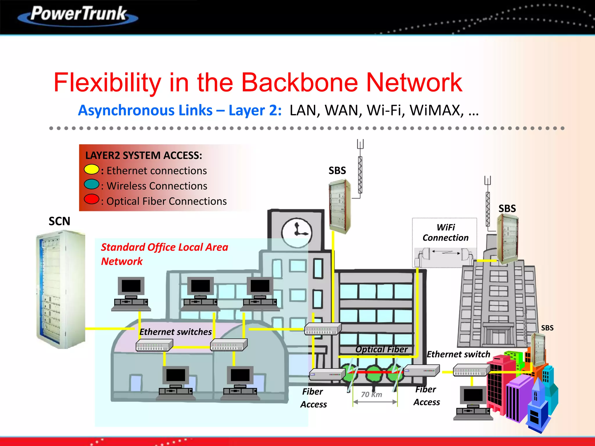
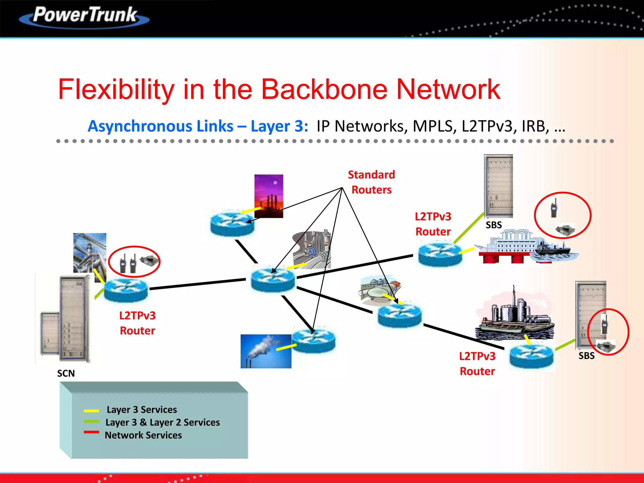
Flexibility in the Backbone Network](https://image.slidesharecdn.com/prosandconsofp25vstetra-170728033631/75/Pros-and-cons_of_p25_vs_tetra-27-2048.jpg)


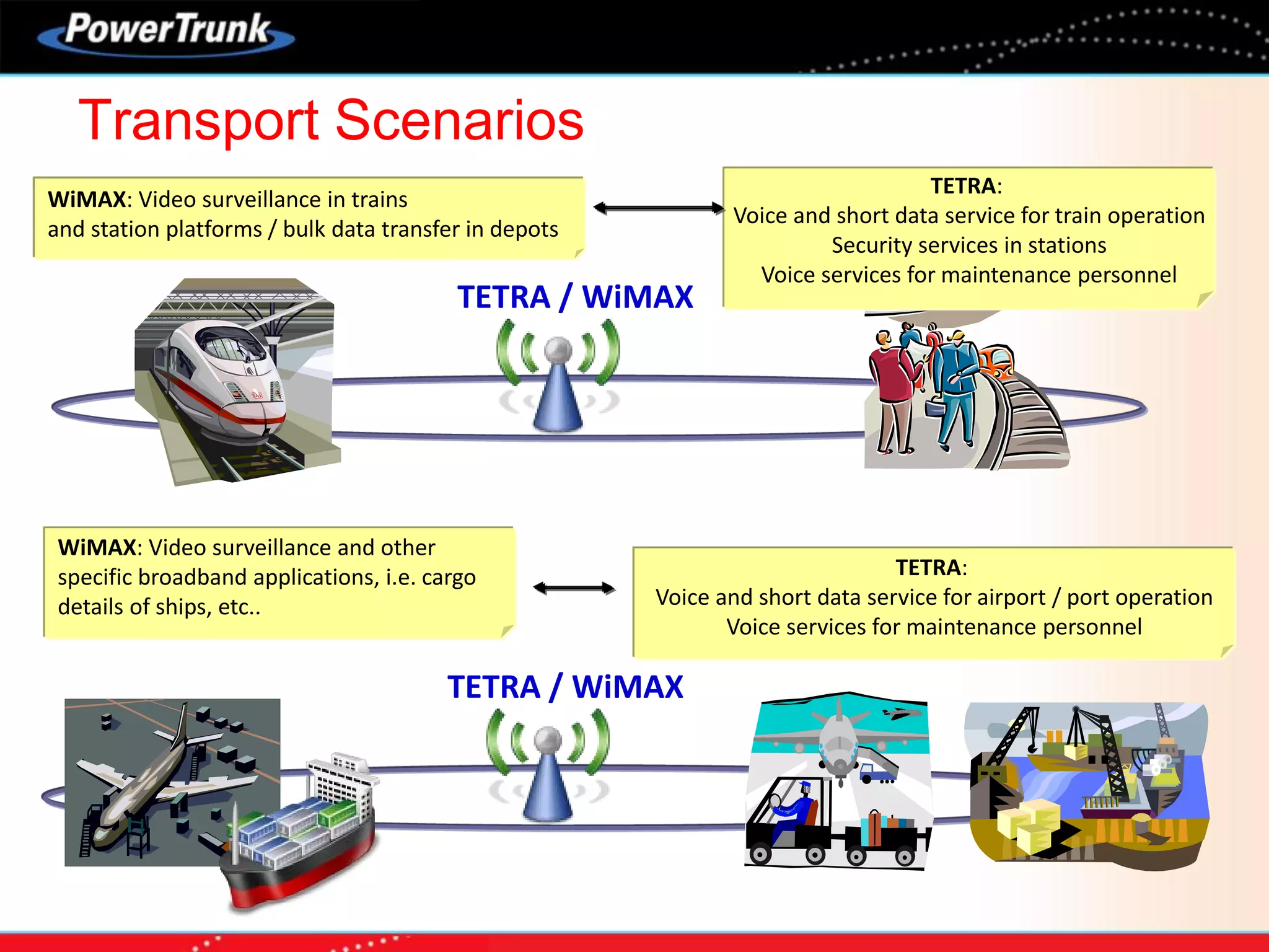


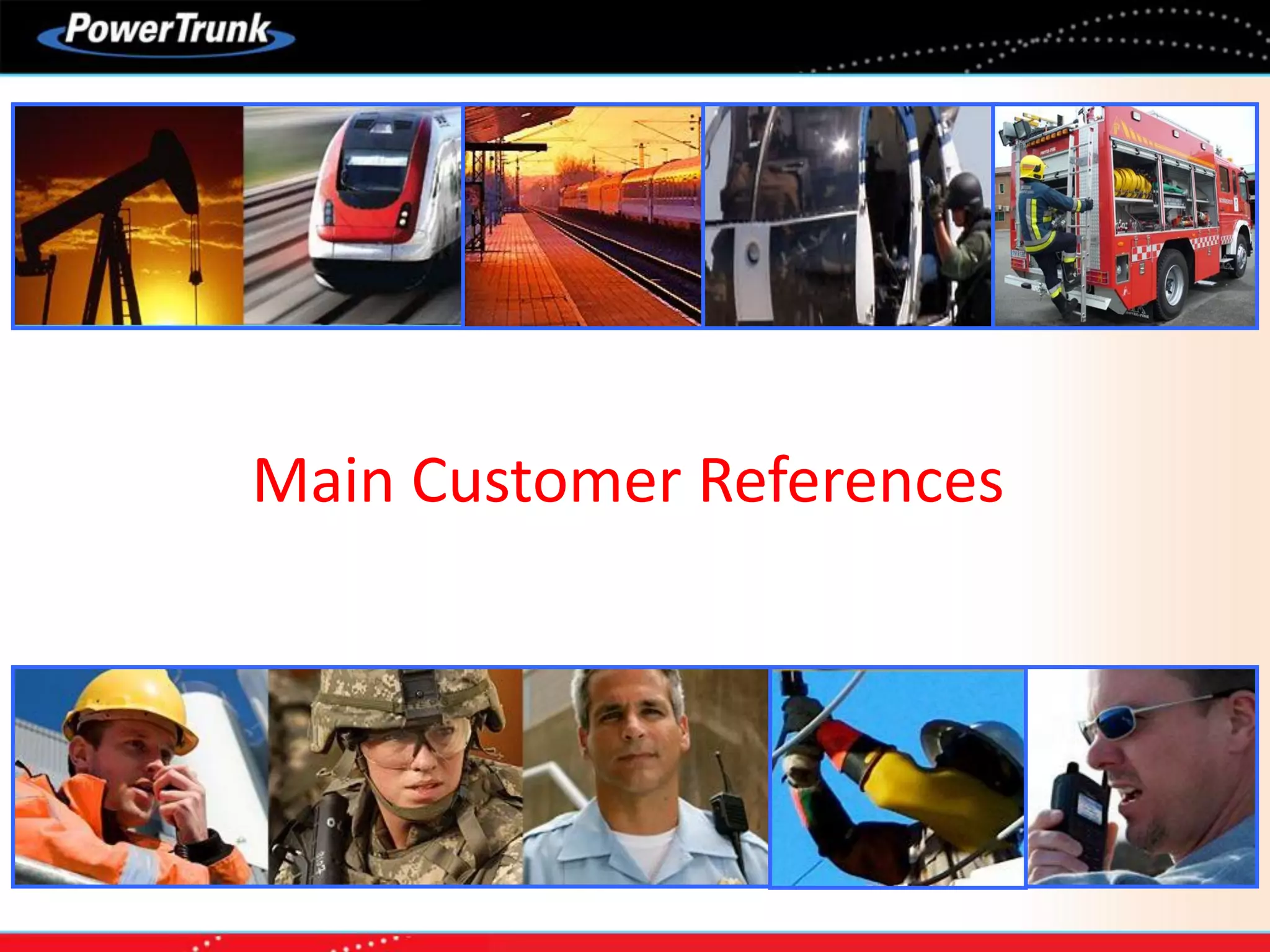


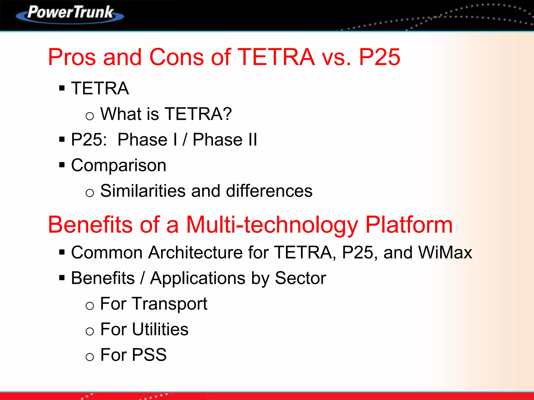
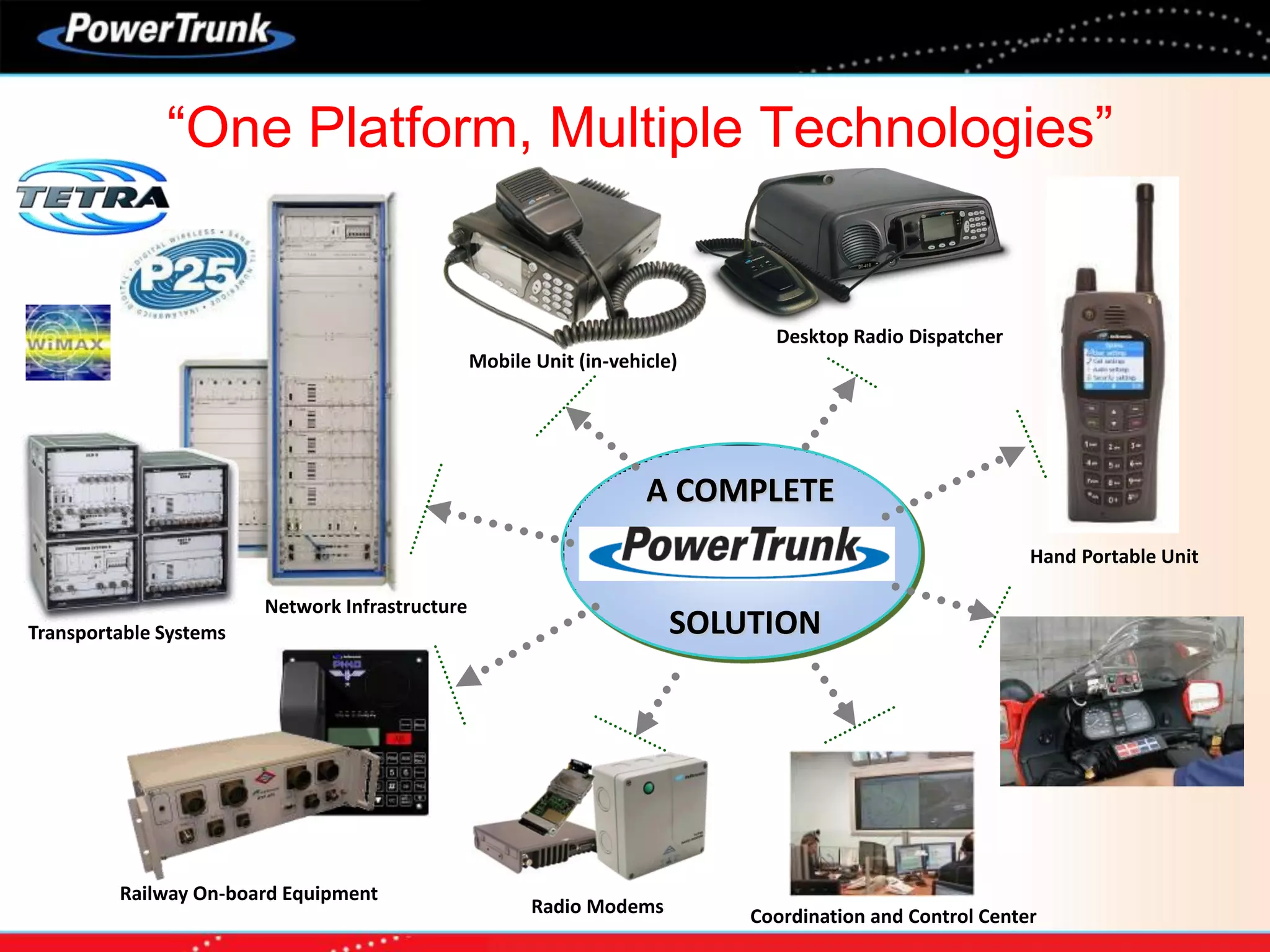


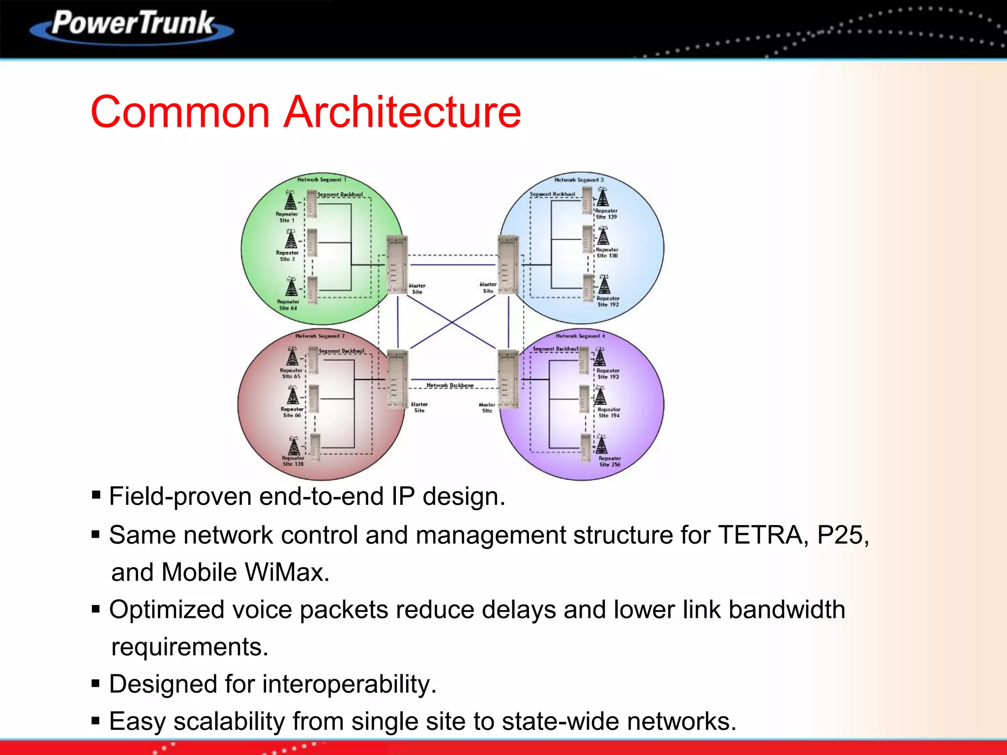
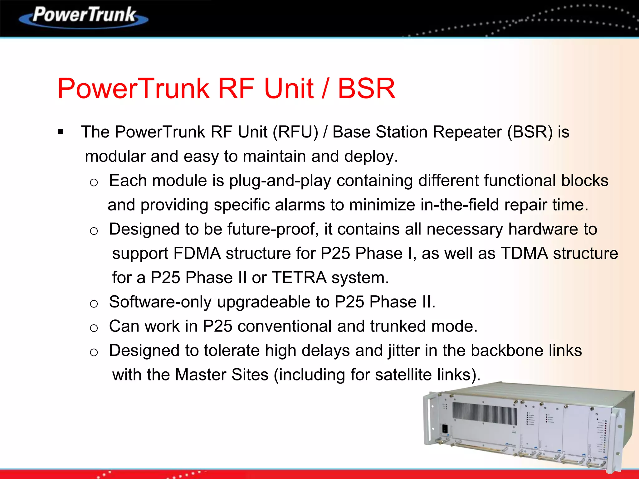
This document discusses and compares TETRA and P25 digital radio communication standards. It provides an overview of what TETRA and P25 are, including their key elements and interfaces. The pros and cons of each standard are outlined, noting that TETRA is optimized for high population density areas while P25 is better suited for wider area coverage. A multi-technology platform is proposed that can support TETRA, P25 Phase I/II, and WiMAX using a common architecture with benefits for different sectors including transport, utilities, and public safety services. Application examples are given for using the standards for transportation communications.


![Gsm rf-optimization[1]](https://cdn.slidesharecdn.com/ss_thumbnails/gsm-rf-optimization1-130923044142-phpapp02-thumbnail.jpg?width=640&height=640&fit=bounds)


