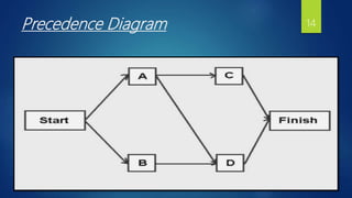
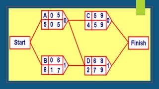
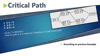
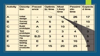
 Presented For: Prof. Imran Ali
 Presented by: Girls Group M.Com II
NETWORK TECHNIQUES in
PROJECT MANAGEMENT
2
 Introduction
3
 Network Planning
 Estimated Time
 CPM
 PERT
TABLE OF
CONTENTS
1
2
3
4
5
 Project
01
 INTRODUCTION
Project:
A project is an interrelated set of activities that
has a definite starting and ending point and that
results in a unique product or service.
Project Management:
Project management is a scientific way of planning, implementing,
monitoring & controlling the various aspects of a project such as
time, money, materials, manpower & other resources.
5
Network Planning
Methods
 Methods used for network planning are:
• CPM
• PERT
Managing a project with network
planning methods involves four steps:
1. Describing the Project.
2. Diagramming the Network.
3. Estimating time of completion.
4. Monitoring Project Progress.
02
04
01
03
6
 Successor
A successor activity is the descriptor to
define a task which occurs following a
predecessor activity. Order is very
important in business.
 EVENT
Event is a step that leads to the action or
status change in the project management. It
has no time and is the start or the end of
the activity. The event is represented by
a node in the network.
 Activity
a task is an activity that needs to be
accomplished within a defined period of
time
 Precedence Relationship
Activities are linked by precedence
relationships to show the sequence in
which the activities are to be performed.
Network Diagram
Concepts
7
Guidelines of Network
Diagraming
 1
Before an activity can
begin, its preceding
activities must be
completed
 2
Arrows indicate logical
precedence
 3
Flow of the diagram is from left
to right
8
 4
Arrows should not
intersect
 5
Dangling should be
avoided
 LETS EXPLAIN PRACTICALLY
• Uses arcs to represent activities and nodes to represent events.
• It is Event Oriented
ACTIVITY ON ARC(AOA):
Dummy Activity
AOA approach requires the addition of a Dummy Activity to clarify the
precedence relationships between the two activities. It is a zero time
activity and consumes no resources.
2) When two or more activities share the same precedence
activity but not all the precedence are shared.
 Dummy Activity is used in two situations:
s
1) When two or more activities start and end at the same
nodes

 Planning the schedule of
the project
FORWARD PASS:
The early start and early finish times are calculated by moving forward
through the network and considering the predecessor activities
Considers maximum
BACKWARD PASS:
The latest start and finish times are calculated by moving backward
through the network. Considers minimum
SLACK TIME:
Slack time for an activity is the difference between its earliest and latest
start time or between the earliest and latest finish time. Critical path is
the path of activities having zero Slack time.
A Simple Project
Precedence Diagram 14
155 KEYWORDS
Critical Path
Methods
 History:
It was developed by J.E.KELLY of REMINGTON-RAND
and M.R.WALKER of DU PONT and the emphasis
was on the trade-off between the cost of project and
its overall completion time. The first test was made
in 1958,when CPM was applied to the construction
of a new chemical plant.
 Definition:
Critical path is the sequence of activities between a
project’s start and finish that takes the longest time
to complete.

 According to previous Example
TIME ESTIMATES
 01
 02
 03
 04
Optimistic time (to)
 It is the shortest time in which the activity can be completed.
Most likely time (tm)
 It is the probable time required to perform the activity
Pessimistic time (tp)
 It is the longest estimated time required to perform an activity
Expected time (te)
 te = to + 4tm + tp
6
PERT 20Steps in PERT
 Identify the specific activities
 1st Step
 Determine proper sequence
of the activities.
 2nd Step
 Construct the network
diagram.
 3rd Step
 Estimate the time required
for each activity.
 4th Step
 Determine the critical path
 5th Step
 Update the PERT chart.
 6th Step
22
A-B-E-F-G = 60
A-C-D-E-F-G = 64 (CRITICAL PATH)
23
• CPM works with fixed deterministic time
• It is useful for repetitive and non-complex
projects with a certain degree of time
estimates.
• CPM includes time-cost trade off
• CPM – for construction projects
 CPM
Difference between CPM & PERT
• It works with probabilistic time
• It is useful for non-repetitive and complex
projects with uncertain time estimates.
• It is restricted to time variable
• PERT – for R&D projects
 PERT
 ANY QUESTIONS?
THANK YOU!

Project Networking Techniques

  • 2.
     Presented For:Prof. Imran Ali  Presented by: Girls Group M.Com II NETWORK TECHNIQUES in PROJECT MANAGEMENT 2
  • 3.
     Introduction 3  NetworkPlanning  Estimated Time  CPM  PERT TABLE OF CONTENTS 1 2 3 4 5
  • 4.
     Project 01  INTRODUCTION Project: Aproject is an interrelated set of activities that has a definite starting and ending point and that results in a unique product or service. Project Management: Project management is a scientific way of planning, implementing, monitoring & controlling the various aspects of a project such as time, money, materials, manpower & other resources.
  • 5.
    5 Network Planning Methods  Methodsused for network planning are: • CPM • PERT Managing a project with network planning methods involves four steps: 1. Describing the Project. 2. Diagramming the Network. 3. Estimating time of completion. 4. Monitoring Project Progress.
  • 6.
    02 04 01 03 6  Successor A successoractivity is the descriptor to define a task which occurs following a predecessor activity. Order is very important in business.  EVENT Event is a step that leads to the action or status change in the project management. It has no time and is the start or the end of the activity. The event is represented by a node in the network.  Activity a task is an activity that needs to be accomplished within a defined period of time  Precedence Relationship Activities are linked by precedence relationships to show the sequence in which the activities are to be performed. Network Diagram Concepts
  • 7.
    7 Guidelines of Network Diagraming 1 Before an activity can begin, its preceding activities must be completed  2 Arrows indicate logical precedence  3 Flow of the diagram is from left to right
  • 8.
    8  4 Arrows shouldnot intersect  5 Dangling should be avoided  LETS EXPLAIN PRACTICALLY
  • 9.
    • Uses arcsto represent activities and nodes to represent events. • It is Event Oriented ACTIVITY ON ARC(AOA):
  • 10.
    Dummy Activity AOA approachrequires the addition of a Dummy Activity to clarify the precedence relationships between the two activities. It is a zero time activity and consumes no resources. 2) When two or more activities share the same precedence activity but not all the precedence are shared.  Dummy Activity is used in two situations: s 1) When two or more activities start and end at the same nodes
  • 11.
      Planning theschedule of the project
  • 12.
    FORWARD PASS: The earlystart and early finish times are calculated by moving forward through the network and considering the predecessor activities Considers maximum BACKWARD PASS: The latest start and finish times are calculated by moving backward through the network. Considers minimum SLACK TIME: Slack time for an activity is the difference between its earliest and latest start time or between the earliest and latest finish time. Critical path is the path of activities having zero Slack time.
  • 13.
  • 14.
  • 15.
  • 17.
    Critical Path Methods  History: Itwas developed by J.E.KELLY of REMINGTON-RAND and M.R.WALKER of DU PONT and the emphasis was on the trade-off between the cost of project and its overall completion time. The first test was made in 1958,when CPM was applied to the construction of a new chemical plant.  Definition: Critical path is the sequence of activities between a project’s start and finish that takes the longest time to complete.
  • 18.
      According toprevious Example
  • 19.
    TIME ESTIMATES  01 02  03  04 Optimistic time (to)  It is the shortest time in which the activity can be completed. Most likely time (tm)  It is the probable time required to perform the activity Pessimistic time (tp)  It is the longest estimated time required to perform an activity Expected time (te)  te = to + 4tm + tp 6
  • 20.
    PERT 20Steps inPERT  Identify the specific activities  1st Step  Determine proper sequence of the activities.  2nd Step  Construct the network diagram.  3rd Step  Estimate the time required for each activity.  4th Step  Determine the critical path  5th Step  Update the PERT chart.  6th Step
  • 22.
    22 A-B-E-F-G = 60 A-C-D-E-F-G= 64 (CRITICAL PATH)
  • 23.
    23 • CPM workswith fixed deterministic time • It is useful for repetitive and non-complex projects with a certain degree of time estimates. • CPM includes time-cost trade off • CPM – for construction projects  CPM Difference between CPM & PERT • It works with probabilistic time • It is useful for non-repetitive and complex projects with uncertain time estimates. • It is restricted to time variable • PERT – for R&D projects  PERT
  • 24.