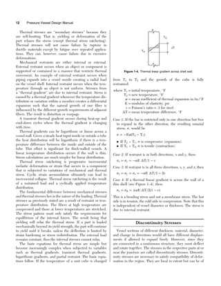
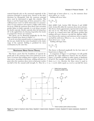
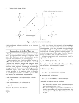
This document discusses stress analysis and failure theories for pressure vessels. It states that pressure vessels designed to ASME code are designed by rules rather than detailed stress analysis. While the code provides thickness and stress formulas, designers must evaluate other loadings and stresses. The document outlines different stress categories and states that membrane stress analysis is commonly used for thin-walled vessels, where stresses are assumed to be uniform across the wall. It discusses two stress failure theories - maximum stress theory, which the code uses, and maximum shear stress theory, which may be more accurate for ductile materials.
This document summarizes the adoption of ASME Y14.5-2009, Dimensioning and Tolerancing, by the Department of Defense as an international standard for engineering drawings and related documentation practices. Key aspects include:
- ASME Y14.5-2009 was adopted on February 9, 2009 for use by the DoD. Proposed changes must be submitted to the DoD Adopting Activity.
- Copies of the standard may be purchased from ASME.
- The standard was developed under procedures accredited by the American National Standards and provides opportunity for public review and comment.
This document provides an overview and contents of an online course about ASME Section I and Section VIII fundamentals. It includes:
- An introduction to the ASME Boiler and Pressure Vessel Code which contains 12 sections covering various topics like power boilers, materials, pressure vessels, welding qualifications, and piping codes.
- Summaries of the scopes and requirements of key sections like Section I (power boilers), Section VIII (pressure vessels), and the B31 piping codes.
- Information on ASME certification and inspection procedures for pressure equipment.
- A note on converting between imperial and metric units in the ASME codes.
- An introduction to the fundamentals and design requirements
Api rp 577 2nd ed. 2013 welding processes, inspection, and metallurgy (1)SERFORTECCIALTDA
This document provides guidelines for welding processes, inspection, and metallurgy according to API standards. It discusses welding inspection tasks before, during, and after welding. These include verifying materials and procedures, monitoring welding parameters, and performing non-destructive testing. It also describes common welding processes like shielded metal arc welding and gas tungsten arc welding. The document outlines how to write welding procedure specifications and qualify welding procedures. Finally, it addresses welding materials, including systems for classifying base and filler metals.
This document provides information about the Casting, Forming & Welding (ME31007) course offered by the Department of Mechanical Engineering. It outlines the course content, schedule, assessment details and references. The course covers casting, forming and welding topics over 19 hours. Welding topics include introduction, processes, energy sources, fluxes, welding arc physics, heat flow, joint design, defects, metallurgy and brazing. Assessment is based on end semester exam, mid semester exam, two class tests and assignments. Lectures cover welding science, heat transfer mechanisms, microstructural zones, continuity mechanisms and specific processes like oxy-fuel gas welding.
1) The document provides information on welding consumables and procedures for welding different types of stainless steel, including austenitic, ferritic, and martensitic stainless steels.
2) Key points covered include the composition and properties of different stainless steel types, recommendations for matching electrodes, preheating requirements, and procedures for welding stainless steel to mild steel.
3) Potential issues that can arise such as cracking, corrosion, and distortion are discussed along with ways to prevent these issues, such as controlling heat input, balancing welding operations, and using post-weld heat treatment.
The document provides an overview of TrusSteel, a division of ITW Building Components Group that manufactures cold-formed steel trusses, outlining the benefits of TrusSteel trusses such as strength, design flexibility, fire resistance, cost effectiveness, and nationwide availability through their network of authorized fabricators. TrusSteel trusses are engineered using proprietary steelVIEW software and feature unique chord sections, webs, fasteners, and structural connections to create a system that offers superior structural performance, quality, safety during handling and installation, and reduces costs for specifiers, designers, contractors and installers. The document
Fatigue occurs when a material is subjected to repeated cyclic stresses that cause cracks to form over time even when the stresses are much lower than the material's strength. The document discusses various types of fatigue loading and summarizes key concepts like fatigue life diagrams, factors that influence fatigue crack growth rates, and methods for analyzing fatigue failure. It provides examples of calculating stress levels to avoid fatigue failure based on a given number of cycles.
The document provides definitions and illustrations of standard test positions and production welding positions. It aims to help users understand the difference between testing positions used for welder qualification and production welding positions encountered in the field. Test positions have discrete definitions and tolerances, while production welding positions are defined contiguously to encompass all possible positions. The document uses diagrams and examples to demonstrate how the positions are defined based on axis inclination and rotation ranges. Key points are that test positions do not necessarily correspond to welding positions, and positions between tests are undefined.
The document describes a spreadsheet program called "LIFTING_LUG" that analyzes lifting lugs used in rigging operations. The program allows the user to input parameters of a lifting lug and determines its ultimate strength based on several checks. It then applies a desired factor of safety to calculate allowable loads for the lifting lug. The program consists of two worksheets - one for documentation and one for performing the lifting lug analysis calculations according to industry standards.
This document provides the 2021 edition of the ASME Boiler and Pressure Vessel Code Section V, which contains requirements and guidelines for nondestructive examination methods. It defines terms related to nondestructive examination and outlines qualification requirements for personnel. The document establishes general requirements for equipment, procedures, calibration, examinations, evaluations, and documentation for various nondestructive examination methods like radiography, ultrasonics, and real-time radioscopy. Appendices provide additional details for specific nondestructive examination methods and exceptions to other industry standards.
ANALYSIS OF A THIN AND THICK WALLED PRESSURE VESSEL FOR DIFFERENT MATERIALS IAEME Publication
In the present work the problem of calculation of the stress developed in the thin and thick cylindrical pressure vessels is numerically solved by using software in C++. The analysis has been done for two different materials pressure vessels. The variations in the thickness of the pressure vessels have been considered for the analysis for different internal pressures. The common characteristic of the pressure vessels solved is that the radial and tangential stresses vary in the same nature of curve for different thickness of vessels.
This document provides an overview and introduction to ASME Section VIII Division 1, which establishes rules for the construction of pressure vessels. It discusses the historical context that led to the development of pressure vessel codes, an overview of ASME's codes and standards, key definitions, and the design requirements and considerations specified in Section VIII Division 1. The document covers topics such as material selection, corrosion allowances, minimum thickness requirements, design pressure, and loadings that must be considered in pressure vessel design.
This document discusses torsional stress and its effects on beams and circular shafts. It makes the following key points:
1. Torsional stress is the shear stress developed in a material subjected to a twisting torque, and is highest at the outermost parts of the material furthest from the central axis.
2. Cracks form under torsional stress and initially appear at the middle of the longest side of a beam, then the shortest side, before circulating around the beam's periphery.
3. Failure of brittle materials under pure torsion occurs along planes inclined to the beam axis, not perpendicular, due to elastic theory principles.
This report summarizes fatigue testing conducted on 10 specimens of AISI 1018 cold rolled steel. The specimens were initially tested under reversed loading conditions. Testing showed significantly higher than expected strength properties, indicating the material may not be 1018 steel or internal stresses from fabrication. To investigate, some specimens underwent annealing and additional testing, including tensile testing, hardness testing, and metallography. Annealing reduced internal stresses as strengths matched expected values post-annealing. The report concludes with appendices detailing each test and analysis conducted.
This document discusses the design of compression members in steel structures. It begins by defining compression members as members subjected to compressive stresses, such as columns, struts, and compression flanges. It notes that compression members are more prone to buckling than tension members. The document then discusses factors that influence the buckling strength of compression members, such as the member's length, cross-sectional properties, end conditions, and bracing. It also discusses eccentric loading of columns and the various sections that can be used or built up for compression members.
Understanding optistruct & LS-Dyna files using text editorAkshay Mistri
This describes basic usage of a text editor in building, editing and organizing FEA model files. Using text editor allows user to do quick changes to a model setup without the use of a pre-processor.
This document provides an overview of heat treatment processes and procedures used at HZW. It defines common heat treatments like normalizing, annealing, stress relieving, and describes how they are applied to different material types. The document also outlines the key components of furnace systems, including thermocouples, compensating cables, PID controllers, and recorders. Standard operating procedures and qualifications for personnel are discussed.
21-Design of Simple Shear Connections (Steel Structural Design & Prof. Shehab...Hossam Shafiq II
1. The document describes the design of a simple shear connection between a beam and column using bolts. It provides equations to check the shear strength of the bolts and bearing strength of the plate.
2. An example is presented to determine the number and size of bolts needed to resist an ultimate shear force of 1000 kN between two beams. It is determined that 7 bolts with 18 mm diameter and 98.5 mm spacing will suffice.
3. The document also checks the strength of double angles used in the connection to transfer the force and confirms the chosen angles are adequate.
ASME B1.20.1 (2014) - Pipe Threads, General Purpose (Inch)..pdfbarrantes1974
This document is an American National Standard that specifies pipe thread dimensions and tolerances for general purpose pipe threads in inches. It defines the tapered pipe thread (NPT) form and specifications as well as other pipe thread types including straight threads for couplings and fixtures. The standard provides dimensions, tolerances, and guidance for inspecting and gaging pipe threads to determine conformance.
The document provides information about the fabrication of a storage buffer vessel at Bharat Heavy Plate and Vessels Limited (BHPV). It discusses the goals of learning fabrication processes and quality inspection methods. It then provides details about the production sectors, introduction to pressure vessels, design considerations, ordering fabrication, non-destructive testing methods, and bill of materials. The key points are that the document outlines the goals, production process, design, fabrication steps, quality testing methods, and materials listing for a storage buffer vessel being manufactured at BHPV.
The document discusses mechanical failure and fracture in materials. It addresses how cracks form and propagate, leading to brittle or ductile fracture depending on the material. Stress concentration at crack tips is a key factor. Fracture toughness and impact testing methods are introduced to characterize a material's resistance to fracture. Fatigue failure from cyclic stresses often initiates at flaws and can occur at stresses below typical strength values. S-N curves relate the cyclic stress amplitude to the lifetime of a material. Temperature and loading conditions also influence failure behavior.
This document provides an overview of casting and forging processes. Casting involves heating metal to a molten state and pouring it into a mold to create a desired shape. Forging uses thermal and mechanical energy to change the shape of steel billets or ingots while in a solid state. The document discusses the casting process, including manufacturing molds, and the forging process, including impression die forging and cold forging. Both casting and forging have advantages - casting allows for large sizes and complicated shapes while forging produces stronger, more durable parts.
The document discusses the origins and development of standards and codes by the American Society of Mechanical Engineers (ASME) beginning in the late 19th century. It describes how early discussions around standardizing parts like bolts and pipes led to the establishment of formal standards committees at ASME. It also explains how ASME published its first widely-adopted standard, the Boiler and Pressure Vessel Code, in response to many boiler explosions resulting from a lack of uniform safety standards. The document outlines ASME's current standards development process and how manufacturers can become accredited to use product certification stamps indicating compliance with ASME codes and standards.
This section will introduce how to solve problems of axially loaded members such as stepped and tapered rods loaded in tension. The concept of strain energy will also be introduced.
The document provides terminology and definitions related to welding inspection of steels. It discusses the duties of a welding inspector, relevant codes and standards, the welding procedure, destructive and non-destructive testing methods, defects, consumables, and welding processes. Key terms defined include types of welds (butt, fillet, edge), types of joints (butt, tee, corner, lap), features of welds (toe, face, root, throat), and sizes of different welds (full penetration butt welds, partial penetration butt welds, fillet welds).
This document provides information about heat treatment of pressure vessels and various heat treatment processes. It discusses the effect of heat treatment on mechanical properties of metals and alloys. Various heat treatment processes like normalizing, annealing, stress relieving, solution annealing, hardening, tempering and aging are described. Parameters for heat treatment of different steel grades are listed. The document also covers thermocouples, recorders, furnace layout and calibration procedures for heat treatment furnaces.
This document discusses various topics related to mechanical design including types of loads and stresses, theories of failure, stress concentration, fatigue, creep, and design of cotter joints. It defines stress and strain, describes different types of loading and the resulting stresses. It discusses various theories of failure for predicting failure under different stress conditions. It also covers stress concentration, factors affecting it, and methods to reduce it. Fatigue behavior is described using S-N curves and endurance limits. Creep behavior and different creep stages are outlined. Design of cotter joints is explained focusing on its components and advantages.
lecturenote_1177425455CAPTER TWO-Design for static strength.pdfPraveen Kumar
1) The document discusses static strength and load design. It describes how static loads do not change over time and can produce tension, compression, shear, bending or torsion stresses.
2) Ideally, strength tests would match the actual loading conditions and part geometry, but this is often not feasible. Instead, published material properties are used, which provides less information for design.
3) Stress concentrations occur where there are geometric changes like holes, notches or threads and increase the stresses beyond nominal values. Various stress concentration factors are used to relate actual and nominal stresses.
Design and Implmentation of Circular Cross Sectional Pressure Vessel Using Pr...IJMER
International Journal of Modern Engineering Research (IJMER) is Peer reviewed, online Journal. It serves as an international archival forum of scholarly research related to engineering and science education.
International Journal of Modern Engineering Research (IJMER) covers all the fields of engineering and science: Electrical Engineering, Mechanical Engineering, Civil Engineering, Chemical Engineering, Computer Engineering, Agricultural Engineering, Aerospace Engineering, Thermodynamics, Structural Engineering, Control Engineering, Robotics, Mechatronics, Fluid Mechanics, Nanotechnology, Simulators, Web-based Learning, Remote Laboratories, Engineering Design Methods, Education Research, Students' Satisfaction and Motivation, Global Projects, and Assessment…. And many more.
The document discusses stress-strain curves, which plot the stress and strain of a material sample under load. It describes the typical stress-strain behavior of ductile materials like steel and brittle materials like concrete. For ductile materials, the curve shows an elastic region, yield point, strain hardening region, and ultimate strength before failure. The yield point marks the transition between elastic and plastic deformation. The document also discusses factors that influence a material's yield stress, such as temperature and strain rate, and implications for structural engineering like reduced buckling strength after yielding.
FAILURE CRITERIA FOR NON-BRITTLE MATERIALSAhmed Abdullah
- The document discusses several failure criteria theories for predicting failure in materials including brittle and ductile materials.
- Rankine's criteria and Mohr's criteria are based on maximum normal stresses and are applicable to brittle materials. Failure occurs when principal stresses reach ultimate tensile or compressive strengths.
- Maximum shear stress and von Mises criteria predict failure in ductile materials based on limiting shear stresses and distortion energy. Failure occurs when maximum shear stresses or distortion energy equals values from uniaxial tension tests.
This document discusses strength and failure theories for composite materials. It introduces failure criteria as methods to predict failure of composites under stress or strain. Maximum stress and maximum strain criteria are described as limit criteria for unidirectional composites. The Tsai-Hill criterion is presented as an interactive failure criterion that accounts for stress interactions. The document then discusses applying failure criteria to predict initial failure in laminates from cracks in transverse plies, and final failure loads beyond first ply failure.
This document discusses stress, strain, and deformation of solids. It provides definitions for key terms like rigid bodies, deformable bodies, stress, strain, stiffness, stability, and ductility. It also describes different models used to simulate rigid and deformable body motion, including mass-spring models and finite element method (FEM) models. Additionally, it covers mechanical properties of materials like strength, stiffness, stability, and ductility. It discusses stress-strain diagrams and properties like elasticity, yield strength, plasticity, necking, and breaking strength for ductile and brittle materials. It also defines true stress and true strain which are important for large deformations, and describes different types of stresses like normal stresses (
This document is a report on stress, strain, and their measurement. It discusses stress and strain concepts such as normal stress, shear stress, tensile strain, and compressive strain. It also examines stress-strain curves and how they are used to determine material properties. Measurement devices for stress and strain are described, including strain gauges. The report concludes that stress and strain are important concepts in mechanics of materials and their measurement allows determination of material behaviors.
This document provides an overview of tensile testing. It discusses tensile specimens, testing machines, stress-strain curves, and key mechanical properties measured by tensile tests such as strength, ductility, and elastic modulus. Tensile tests are used to select materials, ensure quality, compare new materials/processes, and predict behavior under other loads. Stress-strain curves are generated by applying tension to a specimen and recording the resulting force and elongation. Important aspects of the curves, like yield strength and plastic deformation, are defined.
This document summarizes Test Method E 647 for measuring fatigue crack growth rates. It describes the test method, which involves cyclic loading of precracked specimens to determine the rate of crack growth expressed as a function of stress-intensity factor range (DK). Several specimen configurations are provided, and crack growth rates are considered a function of DK and force ratio (R). The test method standardizes how crack growth rate data can be generated and compared to characterize a material's resistance to stable crack extension under cyclic loading conditions.
Tensile testing is used to determine the strength and ductility of materials. A specimen is placed in grips and pulled apart under increasing tensile force while measuring elongation. The resulting stress-strain curve provides properties like yield strength, tensile strength, and Young's modulus. Tensile tests are important for engineering design and quality control by ensuring materials can withstand expected loads and comparing new materials. Common applications include testing aircraft components, bolts, and other loaded structures.
International Journal of Engineering Research and Development (IJERD)IJERD Editor
journal publishing, how to publish research paper, Call For research paper, international journal, publishing a paper, IJERD, journal of science and technology, how to get a research paper published, publishing a paper, publishing of journal, publishing of research paper, reserach and review articles, IJERD Journal, How to publish your research paper, publish research paper, open access engineering journal, Engineering journal, Mathemetics journal, Physics journal, Chemistry journal, Computer Engineering, Computer Science journal, how to submit your paper, peer reviw journal, indexed journal, reserach and review articles, engineering journal, www.ijerd.com, research journals,
yahoo journals, bing journals, International Journal of Engineering Research and Development, google journals, hard copy of journal
Analysis of Stress in Nozzle/Shell of Cylindrical Pressure Vessel under Inter...IJERA Editor
This work a comparative study of the methods of analysis of stress in vessel/nozzle, due to external loads. The
methods of analysis compared are WRC 107, WRC 297 and Method of Finite Elements. To make the
comparison between the methods, one model of nozzle has been developed without reinforcement plate. In this
nozzle it was applied external loads and after the application of the loads, compared the results of stress for the
three methods of analyses considered in this study.
Thermoelastic stress analysis (TSA) measures small temperature changes in materials under load that correspond to stress levels. While failure criteria are not directly based on the sum of principal stresses measured by TSA, it can still predict failure locations. Both finite element analysis (FEA) and TSA are full-field techniques that provide spatial stress distributions. They complement each other, with FEA useful early in design and TSA confirming FEA models through experimental loading. Together, FEA and TSA provide a strong approach for predicting failure.
Ch3 Design Considerations (Steel Bridges تصميم الكباري المعدنية & Prof. Dr. M...Hossam Shafiq II
This chapter discusses design considerations for steel bridges. It outlines two main design philosophies: working stress design and limit states design. The chapter then focuses on the working stress design method, which is based on the Egyptian Code of Practice for Steel Constructions and Bridges. It provides allowable stress values for various steel grades and loading conditions, including stresses due to axial, shear, bending, compression and tension loads. Design of sections is classified based on compact and slender criteria. The chapter also addresses stresses from repeated, erection and secondary loads.
The document discusses stress concentration and fatigue failure in machine elements. It defines stress concentration as irregular stress distribution caused by abrupt changes in cross-section shape. Stress concentration factors are introduced to quantify the maximum stress compared to nominal stress. The document also discusses endurance limit and fatigue strength testing methods. Factors that affect fatigue strength like material properties, surface finish, size and temperature are summarized. Methods to evaluate and reduce stress concentration in designs are provided.
This document summarizes research on fatigue analysis of the joint between an aircraft's fuselage and wing. It describes fatigue as the progressive failure of materials from cyclic loading. The study designs a new wing-bracket attachment and analyzes the fatigue life of this joint when made from maraging steel, titanium, or A36 steel. Through CATIA and ANSYS modeling as well as hand calculations, it determines that maraging steel provides the greatest fatigue life for the wing-bracket joint. The research aims to improve aircraft structural component design through fatigue analysis.
This document summarizes key concepts from a chapter on strain in mechanics of materials. It discusses two main types of strain - normal and shear - and how stress and strain define a material's mechanical properties. It then focuses on axial deformation and stress-strain diagrams, describing how tensile tests are conducted to generate these diagrams for materials like steel. Key points on the stress-strain curve are identified, such as proportional limit, yield point, ultimate stress, and how they relate to a material's elastic region and factors of safety in design.
The document discusses tensile strength and tensile testing. It defines tensile strength as the maximum stress a material can withstand under tension before necking and breaking. A tensile test measures how a material responds to tensile forces by recording the load and elongation of a test specimen. The results are displayed as a stress-strain curve which can show properties like yield strength, ultimate tensile strength, modulus of elasticity, and ductility measures.
The document discusses tensile strength and tensile testing. It defines tensile strength as the maximum stress a material can withstand under tension before necking and breaking. A tensile test measures how a material responds to tensile forces by recording the load and elongation of a test specimen. The results are used to determine various tensile properties including modulus of elasticity, yield strength, ultimate tensile strength, and measures of ductility. Hooke's law and concepts like strain, stress-strain curves, and necking are also explained in the context of understanding a material's tensile behavior.
Similar to Pressure Vessel Design Manual-STRESS.pdf (20)
Batteries -Introduction – Types of Batteries – discharging and charging of battery - characteristics of battery –battery rating- various tests on battery- – Primary battery: silver button cell- Secondary battery :Ni-Cd battery-modern battery: lithium ion battery-maintenance of batteries-choices of batteries for electric vehicle applications.
Fuel Cells: Introduction- importance and classification of fuel cells - description, principle, components, applications of fuel cells: H2-O2 fuel cell, alkaline fuel cell, molten carbonate fuel cell and direct methanol fuel cells.
CHINA’S GEO-ECONOMIC OUTREACH IN CENTRAL ASIAN COUNTRIES AND FUTURE PROSPECTjpsjournal1
The rivalry between prominent international actors for dominance over Central Asia's hydrocarbon
reserves and the ancient silk trade route, along with China's diplomatic endeavours in the area, has been
referred to as the "New Great Game." This research centres on the power struggle, considering
geopolitical, geostrategic, and geoeconomic variables. Topics including trade, political hegemony, oil
politics, and conventional and nontraditional security are all explored and explained by the researcher.
Using Mackinder's Heartland, Spykman Rimland, and Hegemonic Stability theories, examines China's role
in Central Asia. This study adheres to the empirical epistemological method and has taken care of
objectivity. This study analyze primary and secondary research documents critically to elaborate role of
china’s geo economic outreach in central Asian countries and its future prospect. China is thriving in trade,
pipeline politics, and winning states, according to this study, thanks to important instruments like the
Shanghai Cooperation Organisation and the Belt and Road Economic Initiative. According to this study,
China is seeing significant success in commerce, pipeline politics, and gaining influence on other
governments. This success may be attributed to the effective utilisation of key tools such as the Shanghai
Cooperation Organisation and the Belt and Road Economic Initiative.
Understanding Inductive Bias in Machine LearningSUTEJAS
This presentation explores the concept of inductive bias in machine learning. It explains how algorithms come with built-in assumptions and preferences that guide the learning process. You'll learn about the different types of inductive bias and how they can impact the performance and generalizability of machine learning models.
The presentation also covers the positive and negative aspects of inductive bias, along with strategies for mitigating potential drawbacks. We'll explore examples of how bias manifests in algorithms like neural networks and decision trees.
By understanding inductive bias, you can gain valuable insights into how machine learning models work and make informed decisions when building and deploying them.
Harnessing WebAssembly for Real-time Stateless Streaming PipelinesChristina Lin
Traditionally, dealing with real-time data pipelines has involved significant overhead, even for straightforward tasks like data transformation or masking. However, in this talk, we’ll venture into the dynamic realm of WebAssembly (WASM) and discover how it can revolutionize the creation of stateless streaming pipelines within a Kafka (Redpanda) broker. These pipelines are adept at managing low-latency, high-data-volume scenarios.
A SYSTEMATIC RISK ASSESSMENT APPROACH FOR SECURING THE SMART IRRIGATION SYSTEMSIJNSA Journal
The smart irrigation system represents an innovative approach to optimize water usage in agricultural and landscaping practices. The integration of cutting-edge technologies, including sensors, actuators, and data analysis, empowers this system to provide accurate monitoring and control of irrigation processes by leveraging real-time environmental conditions. The main objective of a smart irrigation system is to optimize water efficiency, minimize expenses, and foster the adoption of sustainable water management methods. This paper conducts a systematic risk assessment by exploring the key components/assets and their functionalities in the smart irrigation system. The crucial role of sensors in gathering data on soil moisture, weather patterns, and plant well-being is emphasized in this system. These sensors enable intelligent decision-making in irrigation scheduling and water distribution, leading to enhanced water efficiency and sustainable water management practices. Actuators enable automated control of irrigation devices, ensuring precise and targeted water delivery to plants. Additionally, the paper addresses the potential threat and vulnerabilities associated with smart irrigation systems. It discusses limitations of the system, such as power constraints and computational capabilities, and calculates the potential security risks. The paper suggests possible risk treatment methods for effective secure system operation. In conclusion, the paper emphasizes the significant benefits of implementing smart irrigation systems, including improved water conservation, increased crop yield, and reduced environmental impact. Additionally, based on the security analysis conducted, the paper recommends the implementation of countermeasures and security approaches to address vulnerabilities and ensure the integrity and reliability of the system. By incorporating these measures, smart irrigation technology can revolutionize water management practices in agriculture, promoting sustainability, resource efficiency, and safeguarding against potential security threats.
Presentation of IEEE Slovenia CIS (Computational Intelligence Society) Chapte...University of Maribor
Slides from talk presenting:
Aleš Zamuda: Presentation of IEEE Slovenia CIS (Computational Intelligence Society) Chapter and Networking.
Presentation at IcETRAN 2024 session:
"Inter-Society Networking Panel GRSS/MTT-S/CIS
Panel Session: Promoting Connection and Cooperation"
IEEE Slovenia GRSS
IEEE Serbia and Montenegro MTT-S
IEEE Slovenia CIS
11TH INTERNATIONAL CONFERENCE ON ELECTRICAL, ELECTRONIC AND COMPUTING ENGINEERING
3-6 June 2024, Niš, Serbia
Introduction- e - waste – definition - sources of e-waste– hazardous substances in e-waste - effects of e-waste on environment and human health- need for e-waste management– e-waste handling rules - waste minimization techniques for managing e-waste – recycling of e-waste - disposal treatment methods of e- waste – mechanism of extraction of precious metal from leaching solution-global Scenario of E-waste – E-waste in India- case studies.
Using recycled concrete aggregates (RCA) for pavements is crucial to achieving sustainability. Implementing RCA for new pavement can minimize carbon footprint, conserve natural resources, reduce harmful emissions, and lower life cycle costs. Compared to natural aggregate (NA), RCA pavement has fewer comprehensive studies and sustainability assessments.
Embedded machine learning-based road conditions and driving behavior monitoringIJECEIAES
Car accident rates have increased in recent years, resulting in losses in human lives, properties, and other financial costs. An embedded machine learning-based system is developed to address this critical issue. The system can monitor road conditions, detect driving patterns, and identify aggressive driving behaviors. The system is based on neural networks trained on a comprehensive dataset of driving events, driving styles, and road conditions. The system effectively detects potential risks and helps mitigate the frequency and impact of accidents. The primary goal is to ensure the safety of drivers and vehicles. Collecting data involved gathering information on three key road events: normal street and normal drive, speed bumps, circular yellow speed bumps, and three aggressive driving actions: sudden start, sudden stop, and sudden entry. The gathered data is processed and analyzed using a machine learning system designed for limited power and memory devices. The developed system resulted in 91.9% accuracy, 93.6% precision, and 92% recall. The achieved inference time on an Arduino Nano 33 BLE Sense with a 32-bit CPU running at 64 MHz is 34 ms and requires 2.6 kB peak RAM and 139.9 kB program flash memory, making it suitable for resource-constrained embedded systems.
1. 1
Stresses in PressureVessels
DESIGN PHILOSOPHY
In general, pressure vessels designed in accordance with
the ASME Code, Section VIII, Division 1, are designed by
rules and do not require a detailed evaluation of all stresses.
It is recognized that high localized and secondary bending
stresses may exist but are allowed for by use of a higher
safety factor and design rules for details. It is required, how-
ever, that all loadings (the forces applied to a vessel or its
structural attachments) must be considered. (See Reference 1,
Para. UG-22.)
While the Code gives formulas for thickness and stress of
basic components, it is up to the designer to select appro-
priate analytical procedures for determining stress due to
other loadings. The designer must also select the most prob-
able combination of simultaneous loads for an economical
and safe design.
The Code establishes allowable stresses by stating in Para.
UG-23(c) that the maximum general primary membrane
stress must be less than allowable stresses outlined in material
sections. Further, it states that the maximum primary mem-
brane stress plus primary bending stress may not exceed 1.5
times the allowable stress of the material sections. In other
sections, specifically Paras. 1-5(e) and 2-8, higher allowable
stresses are permitted if appropriate analysis is made. These
higher allowable stresses clearly indicate that different stress
levels for different stress categories are acceptable.
It is general practice when doing more detailed stress
analysis to apply higher allowable stresses. In effect, the
detailed evaluation of stresses permits substituting knowl-
edge of localized stresses and the use of higher allowables
in place of the larger factor of safety used by the Code. This
higher safety factor really reflected lack of knowledge about
actual stresses.
A calculated value of stress means little until it is associ-
ated with its location and distribution in the vessel and with
the type of loading that produced it. Different types of stress
have different degrees of significance.
The designer must familiarize himself with the various
types of stress and loadings in order to accurately apply
the results of analysis. The designer must also consider
some adequate stress or failure theory in order to combine
stresses and set allowable stress limits. It is against this fail-
ure mode that he must compare and interpret stress values,
and define how the stresses in a component react and con-
tribute to the strength of that part.
The following sections will provide the fundamental
knowledge for applying the results of analysis. The topics
covered in Chapter 1 form the basis by which the rest of
the book is to be used. A section on special problems and
considerations is included to alert the designer to more com-
plex problems that exist.
STRESS ANALYSIS
Stress analysis is the determination of the relationship
between external forces applied to a vessel and the corre-
sponding stress. The emphasis of this book is not how to do
stress analysis in particular, but rather how to analyze vessels
and their component parts in an effort to arrive at an
economical and safe design––the difference being that we
analyze stresses where necessary to determine thickness of
material and sizes of members. We are not so concerned
with building mathematical models as with providing a
step-by-step approach to the design of ASME Code vessels.
It is not necessary to find every stress but rather to know the
governing stresses and how they relate to the vessel or its
respective parts, attachments, and supports.
The starting place for stress analysis is to determine all
the design conditions for a given problem and then deter-
mine all the related external forces. We must then relate
these external forces to the vessel parts which must resist
them to find the corresponding stresses. By isolating the
causes (loadings), the effects (stress) can be more accurately
determined.
The designer must also be keenly aware of the types of
loads and how they relate to the vessel as a whole. Are the
1
2. effects long or short term? Do they apply to a localized
portion of the vessel or are they uniform throughout?
How these stresses are interpreted and combined, what
significance they have to the overall safety of the vessel, and
what allowable stresses are applied will be determined by
three things:
1. The strength/failure theory utilized.
2. The types and categories of loadings.
3. The hazard the stress represents to the vessel.
Membrane Stress Analysis
Pressure vessels commonly have the form of spheres,
cylinders, cones, ellipsoids, tori, or composites of these.
When the thickness is small in comparison with other dimen-
sions (Rm/t > 10), vessels are referred to as membranes and
the associated stresses resulting from the contained pressure
are called membrane stresses. These membrane stresses are
average tension or compression stresses. They are assumed
to be uniform across the vessel wall and act tangentially to its
surface. The membrane or wall is assumed to offer no resis-
tance to bending. When the wall offers resistance to bend-
ing, bending stresses occur in addition to membrane stresses.
In a vessel of complicated shape subjected to internal
pressure, the simple membrane-stress concepts do not suf-
fice to give an adequate idea of the true stress situation. The
types of heads closing the vessel, effects of supports, varia-
tions in thickness and cross section, nozzles, external at-
tachments, and overall bending due to weight, wind, and
seismic activity all cause varying stress distributions in the
vessel. Deviations from a true membrane shape set up bend-
ing in the vessel wall and cause the direct loading to vary
from point to point. The direct loading is diverted from the
more flexible to the more rigid portions of the vessel. This
effect is called ‘‘stress redistribution.’’
In any pressure vessel subjected to internal or external
pressure, stresses are set up in the shell wall. The state of
stress is triaxial and the three principal stresses are:
x ¼ longitudinal/meridional stress
¼ circumferential/latitudinal stress
r ¼ radial stress
In addition, there may be bending and shear stresses. The
radial stress is a direct stress, which is a result of the pressure
acting directly on the wall, and causes a compressive stress
equal to the pressure. In thin-walled vessels this stress is so
small compared to the other ‘‘principal’’ stresses that it is
generally ignored. Thus we assume for purposes of analysis
that the state of stress is biaxial. This greatly simplifies the
method of combining stresses in comparison to triaxial stress
states. For thickwalled vessels (Rm/t 10), the radial stress
cannot be ignored and formulas are quite different from
those used in finding ‘‘membrane stresses’’ in thin shells.
Since ASME Code, Section VIII, Division 1, is basically for
design by rules, a higher factor of safety is used to allow for
the ‘‘unknown’’ stresses in the vessel. This higher safety
factor, which allows for these unknown stresses, can impose
a penalty on design but requires much less analysis. The
design techniques outlined in this text are a compro-
mise between finding all stresses and utilizing minimum
code formulas. This additional knowledge of stresses warrants
the use of higher allowable stresses in some cases, while meet-
ing the requirements that all loadings be considered.
In conclusion, ‘‘membrane stress analysis’’ is not completely
accurate but allows certain simplifying assumptions to be
made while maintaining a fair degree of accuracy. The main
simplifying assumptions are that the stress is biaxial and that
the stresses are uniform across the shell wall. For thin-walled
vessels these assumptions have proven themselves to be
reliable. No vessel meets the criteria of being a true
membrane, but we can use this tool with a reasonable
degree of accuracy.
STRESS/FAILURE THEORIES
As stated previously, stresses are meaningless until com-
pared to some stress/failure theory. The significance of a
given stress must be related to its location in the vessel
and its bearing on the ultimate failure of that vessel.
Historically, various ‘‘theories’’ have been derived to com-
bine and measure stresses against the potential failure
mode. A number of stress theories, also called ‘‘yield cri-
teria,’’ are available for describing the effects of combined
stresses. For purposes of this book, as these failure theories
apply to pressure vessels, only two theories will be discussed.
They are the ‘‘maximum stress theory’’ and the ‘‘maximum
shear stress theory.’’
Maximum Stress Theory
This theory is the oldest, most widely used and simplest to
apply. Both ASME Code, Section VIII, Division 1, and
Section I use the maximum stress theory as a basis for
design. This theory simply asserts that the breakdown of
2 Pressure Vessel Design Manual
3. material depends only on the numerical magnitude of the
maximum principal or normal stress. Stresses in the other
directions are disregarded. Only the maximum principal
stress must be determined to apply this criterion. This
theory is used for biaxial states of stress assumed in a thin-
walled pressure vessel. As will be shown later it is unconser-
vative in some instances and requires a higher safety factor
for its use. While the maximum stress theory does accurately
predict failure in brittle materials, it is not always accurate
for ductile materials. Ductile materials often fail along lines
45
to the applied force by shearing, long before the tensile
or compressive stresses are maximum.
This theory can be illustrated graphically for the four
states of biaxial stress shown in Figure 1-1.
It can be seen that uniaxial tension or compression lies on
the two axes. Inside the box (outer boundaries) is the elastic
range of the material. Yielding is predicted for stress
combinations by the outer line.
Maximum Shear Stress Theory
This theory asserts that the breakdown of material de-
pends only on the maximum shear stress attained in an ele-
ment. It assumes that yielding starts in planes of maximum
shear stress. According to this theory, yielding will start at a
point when the maximum shear stress at that point reaches
one-half of the the uniaxial yield strength, Fy. Thus for a
biaxial state of stress where 1 2, the maximum shear
stress will be (1 2)/2.
Yielding will occur when
1 2
2
¼
Fy
2
Both ASME Code, Section VIII, Division 2 and ASME
Code, Section III, utilize the maximum shear stress criterion.
This theory closely approximates experimental results and is
also easy to use. This theory also applies to triaxial states
of stress. In a triaxial stress state, this theory predicts that
yielding will occur whenever one-half the algebraic differ-
ence between the maximum and minimum stress is equal to
one-half the yield stress. Where 1 2 3, the maximum
shear stress is (1 3)/2.
Yielding will begin when
1 3
2
¼
Fy
2
This theory is illustrated graphically for the four states of
biaxial stress in Figure 1-2.
A comparison of Figure 1-1 and Figure 1-2 will quickly
illustrate the major differences between the two theories.
Figure 1-2 predicts yielding at earlier points in Quadrants
II and IV. For example, consider point B of Figure 1-2. It
shows 2 ¼ ()1; therefore the shear stress is equal to
2 (1)/2, which equals 2 þ 1/2 or one-half the stress
1.0
1.0
1.0
1.0
II
0
Safety factor boundary
imposed by ASME Code
Failure surface (yield surface) boundary
I
III IV
σ1
σ1
σ2
σ1
σ2
σ1
σ2
σ1
σ2
Figure 1-1. Graph of maximum stress theory. Quadrant I: biaxial tension; Quadrant II: tension; Quadrant III: biaxial compression; Quadrant IV:
compression.
Stresses in Pressure Vessels 3
4. which would cause yielding as predicted by the maximum
stress theory!
Comparison of the Two Theories
Both theories are in agreement for uniaxial stress or when
one of the principal stresses is large in comparison to the
others. The discrepancy between the theories is greatest
when both principal stresses are numerically equal.
For simple analysis upon which the thickness formulas for
ASME Code, Section I or Section VIII, Division 1, are based,
it makes little difference whether the maximum stress
theory or maximum shear stress theory is used. For example,
according to the maximum stress theory, the controlling
stress governing the thickness of a cylinder is , circumfer-
ential stress, since it is the largest of the three principal
stresses. According to the maximum shear stress theory,
the controlling stress would be one-half the algebraic differ-
ence between the maximum and minimum stress:
. The maximum stress is the circumferential stress,
¼ PR=t
. The minimum stress is the radial stress, r
r ¼ P
Therefore, the maximum shear stress is:
r
2
ASME Code, Section VIII, Division 2, and Section III use
the term ‘‘stress intensity,’’ which is defined as twice the
maximum shear stress. Since the shear stress is compared
to one-half the yield stress only, ‘‘stress intensity’’ is used for
comparison to allowable stresses or ultimate stresses. To
define it another way, yielding begins when the ‘‘stress in-
tensity’’ exceeds the yield strength of the material.
In the preceding example, the ‘‘stress intensity’’ would be
equal to r. And
r ¼ PR=t ðPÞ ¼ PR=t þ P
For a cylinder where P ¼ 300 psi, R ¼ 30 in., and t ¼ .5 in.,
the two theories would compare as follows:
. Maximum stress theory
¼ ¼ PR=t ¼ 300ð30Þ=:5 ¼ 18,000 psi
. Maximum shear stress theory
¼ PR=t þ P ¼ 300ð30Þ=:5 þ 300 ¼ 18,300 psi
Two points are obvious from the foregoing:
1. For thin-walled pressure vessels, both theories yield
approximately the same results.
2. For thin-walled pressure vessels the radial stress is so
small in comparison to the other principal stresses that
it can be ignored and a state of biaxial stress is assumed
to exist.
σ1 σ1
σ2
1.0
0 1.0
1.0
1.0
I
II
III
IV
Point B
Failure surface (yield surface boundary)
σ2
σ1
σ2
σ1
σ2
σ1
σ2
Figure 1-2. Graph of maximum shear stress theory.
4 Pressure Vessel Design Manual
5. For thick-walled vessels (Rm/t 10), the radial stress
becomes significant in defining the ultimate failure of the
vessel. The maximum stress theory is unconservative for
designing these vessels. For this reason, this text has limited
its application to thin-walled vessels where a biaxial state of
stress is assumed to exist.
FAILURES IN PRESSURE VESSELS
Vessel failures can be grouped into four major categories,
which describe why a vessel failure occurs. Failures can also
be grouped into types of failures, which describe how
the failure occurs. Each failure has a why and how to its
history. It may have failed through corrosion fatigue because
the wrong material was selected! The designer must be as
familiar with categories and types of failure as with cate-
gories and types of stress and loadings. Ultimately they are
all related.
Categories of Failures
1. Material—Improper selection of material; defects in
material.
2. Design—Incorrect design data; inaccurate or incor-
rect design methods; inadequate shop testing.
3. Fabrication—Poor quality control; improper or insuf-
ficient fabrication procedures including welding; heat
treatment or forming methods.
4. Service—Change of service condition by the user;
inexperienced operations or maintenance personnel;
upset conditions. Some types of service which require
special attention both for selection of material, design
details, and fabrication methods are as follows:
a. Lethal
b. Fatigue (cyclic)
c. Brittle (low temperature)
d. High temperature
e. High shock or vibration
f. Vessel contents
. Hydrogen
. Ammonia
. Compressed air
. Caustic
. Chlorides
T
ypes of Failures
1. Elastic deformation—Elastic instability or elastic buck-
ling, vessel geometry, and stiffness as well as properties
of materials are protection against buckling.
2. Brittle fracture—Can occur at low or intermediate tem-
peratures. Brittle fractures have occurred in vessels
made of low carbon steel in the 40
–50
F range
during hydrotest where minor flaws exist.
3. Excessive plastic deformation—The primary and sec-
ondary stress limits as outlined in ASME Section
VIII, Division 2, are intended to prevent excessive plas-
tic deformation and incremental collapse.
4. Stress rupture—Creep deformation as a result of fa-
tigue or cyclic loading, i.e., progressive fracture.
Creep is a time-dependent phenomenon, whereas fa-
tigue is a cycle-dependent phenomenon.
5. Plastic instability—Incremental collapse; incremental
collapse is cyclic strain accumulation or cumulative
cyclic deformation. Cumulative damage leads to insta-
bility of vessel by plastic deformation.
6. High strain—Low cycle fatigue is strain-governed and
occurs mainly in lower-strength/high-ductile materials.
7. Stress corrosion—It is well known that chlorides cause
stress corrosion cracking in stainless steels; likewise
caustic service can cause stress corrosion cracking in
carbon steels. Material selection is critical in these
services.
8. Corrosion fatigue—Occurs when corrosive and fatigue
effects occur simultaneously. Corrosion can reduce fa-
tigue life by pitting the surface and propagating cracks.
Material selection and fatigue properties are the major
considerations.
In dealing with these various modes of failure, the de-
signer must have at his disposal a picture of the state of
stress in the various parts. It is against these failure modes
that the designer must compare and interpret stress values.
But setting allowable stresses is not enough! For elastic
instability one must consider geometry, stiffness, and the
properties of the material. Material selection is a major con-
sideration when related to the type of service. Design details
and fabrication methods are as important as ‘‘allowable
stress’’ in design of vessels for cyclic service. The designer
and all those persons who ultimately affect the design must
have a clear picture of the conditions under which the vessel
will operate.
Stresses in Pressure Vessels 5
6. LOADINGS
Loadings or forces are the ‘‘causes’’ of stresses in pres-
sure vessels. These forces and moments must be isolated
both to determine where they apply to the vessel and
when they apply to a vessel. Categories of loadings
define where these forces are applied. Loadings may be
applied over a large portion (general area) of the vessel or
over a local area of the vessel. Remember both general
and local loads can produce membrane and bending
stresses. These stresses are additive and define the overall
state of stress in the vessel or component. Stresses from
local loads must be added to stresses from general load-
ings. These combined stresses are then compared to an
allowable stress.
Consider a pressurized, vertical vessel bending due to
wind, which has an inward radial force applied locally.
The effects of the pressure loading are longitudinal and
circumferential tension. The effects of the wind loading
are longitudinal tension on the windward side and lon-
gitudinal compression on the leeward side. The effects of
the local inward radial load are some local membrane stres-
ses and local bending stresses. The local stresses would be
both circumferential and longitudinal, tension on the inside
surface of the vessel, and compressive on the outside. Of
course the steel at any given point only sees a certain level
of stress or the combined effect. It is the designer’s job to
combine the stresses from the various loadings to arrive at
the worst probable combination of stresses, combine them
using some failure theory, and compare the results to an
acceptable stress level to obtain an economical and safe
design.
This hypothetical problem serves to illustrate how cate-
gories and types of loadings are related to the stresses they
produce. The stresses applied more or less continuously and
uniformly across an entire section of the vessel are primary
stresses.
The stresses due to pressure and wind are primary mem-
brane stresses. These stresses should be limited to the code
allowable. These stresses would cause the bursting or
collapse of the vessel if allowed to reach an unacceptably
high level.
On the other hand, the stresses from the inward radial
load could be either a primary local stress or secondary
stress. It is a primary local stress if it is produced from an
unrelenting load or a secondary stress if produced by a
relenting load. Either stress may cause local deformation
but will not in and of itself cause the vessel to fail. If it is
a primary stress, the stress will be redistributed; if it is a
secondary stress, the load will relax once slight deforma-
tion occurs.
Also be aware that this is only true for ductile materials. In
brittle materials, there would be no difference between
primary and secondary stresses. If the material cannot
yield to reduce the load, then the definition of secondary
stress does not apply! Fortunately current pressure vessel
codes require the use of ductile materials.
This should make it obvious that the type and category of
loading will determine the type and category of stress. This
will be expanded upon later, but basically each combina-
tion of stresses (stress categories) will have different allow-
ables, i.e.:
. Primary stress: Pm SE
. Primary membrane local (PL):
PL ¼ Pm þ PL 1:5 SE
PL ¼ Pm þ Qm 1:5 SE
. Primary membrane þ secondary (Q):
Pm þ Q 3 SE
But what if the loading was of relatively short duration? This
describes the ‘‘type’’ of loading. Whether a loading is steady,
more or less continuous, or nonsteady, variable, or tempo-
rary will also have an effect on what level of stress will be
acceptable. If in our hypothetical problem the loading had
been pressure þ seismic þ local load, we would have a
different case. Due to the relatively short duration of seismic
loading, a higher ‘‘temporary’’ allowable stress would be ac-
ceptable. The vessel doesn’t have to operate in an earth-
quake all the time. On the other hand, it also shouldn’t fall
down in the event of an earthquake! Structural designs allow
a one-third increase in allowable stress for seismic loadings
for this reason.
For steady loads, the vessel must support these loads more
or less continuously during its useful life. As a result, the
stresses produced from these loads must be maintained to
an acceptable level.
For nonsteady loads, the vessel may experience some
or all of these loadings at various times but not all at once
and not more or less continuously. Therefore a temporarily
higher stress is acceptable.
For general loads that apply more or less uniformly across
an entire section, the corresponding stresses must be lower,
since the entire vessel must support that loading.
For local loads, the corresponding stresses are confined to
a small portion of the vessel and normally fall off rapidly in
distance from the applied load. As discussed previously,
pressurizing a vessel causes bending in certain components.
But it doesn’t cause the entire vessel to bend. The results are
not as significant (except in cyclic service) as those caused by
general loadings. Therefore a slightly higher allowable stress
would be in order.
6 Pressure Vessel Design Manual
7. Loadings can be outlined as follows:
A. Categories of loadings
1. General loads—Applied more or less continuously
across a vessel section.
a. Pressure loads—Internal or external pressure
(design, operating, hydrotest, and hydrostatic
head of liquid).
b. Moment loads—Due to wind, seismic, erection,
transportation.
c. Compressive/tensile loads—Due to dead weight,
installed equipment, ladders, platforms, piping,
and vessel contents.
d. Thermal loads—Hot box design of skirthead
attachment.
2. Local loads—Due to reactions from supports,
internals, attached piping, attached equipment,
i.e., platforms, mixers, etc.
a. Radial load—Inward or outward.
b. Shear load—Longitudinal or circumferential.
c. Torsional load.
d. Tangential load.
e. Moment load—Longitudinal or circumferential.
f. Thermal load.
B. Types of loadings
1. Steady loads—Long-term duration, continuous.
a. Internal/external pressure.
b. Dead weight.
c. Vessel contents.
d. Loadings due to attached piping and equipment.
e. Loadings to and from vessel supports.
f. Thermal loads.
g. Wind loads.
2. Nonsteady loads—Short-term duration; variable.
a. Shop and field hydrotests.
b. Earthquake.
c. Erection.
d. Transportation.
e. Upset, emergency.
f. Thermal loads.
g. Start up, shut down.
STRESS
ASME Code, Section VIII, Division 1 vs.
Division 2
ASME Code, Section VIII, Division 1 does not explicitly
consider the effects of combined stress. Neither does it give
detailed methods on how stresses are combined. ASME
Code, Section VIII, Division 2, on the other hand, provides
specific guidelines for stresses, how they are combined, and
allowable stresses for categories of combined stresses.
Division 2 is design by analysis whereas Division 1 is
design by rules. Although stress analysis as utilized by
Division 2 is beyond the scope of this text, the use of
stress categories, definitions of stress, and allowable stresses
is applicable.
Division 2 stress analysis considers all stresses in a triaxial
state combined in accordance with the maximum shear stress
theory. Division 1 and the procedures outlined in this book
consider a biaxial state of stress combined in accordance with
the maximum stress theory. Just as you would not design
a nuclear reactor to the rules of Division 1, you would
not design an air receiver by the techniques of Division 2.
Each has its place and applications. The following discussion
on categories of stress and allowables will utilize informa-
tion from Division 2, which can be applied in general to all
vessels.
T
ypes, Classes, and Categories of Stress
The shell thickness as computed by Code formulas for
internal or external pressure alone is often not sufficient to
withstand the combined effects of all other loadings.
Detailed calculations consider the effects of each loading
separately and then must be combined to give the total
state of stress in that part. The stresses that are present in
pressure vessels are separated into various classes in accor-
dance with the types of loads that produced them, and the
hazard they represent to the vessel. Each class of stress must
be maintained at an acceptable level and the combined
total stress must be kept at another acceptable level. The
combined stresses due to a combination of loads acting
simultaneously are called stress categories. Please note
that this terminology differs from that given in Division 2,
but is clearer for the purposes intended here.
Classes of stress, categories of stress, and allowable
stresses are based on the type of loading that produced
them and on the hazard they represent to the structure.
Unrelenting loads produce primary stresses. Relenting loads
(self-limiting) produce secondary stresses. General loadings
produce primary membrane and bending stresses. Local
loads produce local membrane and bending stresses.
Primary stresses must be kept lower than secondary stresses.
Stresses in Pressure Vessels 7
8. Primary plus secondary stresses are allowed to be higher
and so on. Before considering the combination of stresses
(categories), we must first define the various types and
classes of stress.
Types of Stress
There are many names to describe types of stress. Enough
in fact to provide a confusing picture even to the experienced
designer. As these stresses apply to pressure vessels, we
group all types of stress into three major classes of stress,
and subdivision of each of the groups is arranged according
to their effect on the vessel. The following list of stresses
describes types of stress without regard to their effect on
the vessel or component. They define a direction of stress
or relate to the application of the load.
1. Tensile 10. Thermal
2. Compressive 11. Tangential
3. Shear 12. Load induced
4. Bending 13. Strain induced
5. Bearing 14. Circumferential
6. Axial 15. Longitudinal
7. Discontinuity 16. Radial
8. Membrane 17. Normal
9. Principal
Classes of Stress
The foregoing list provides examples of types of stress.
It is, however, too general to provide a basis with which
to combine stresses or apply allowable stresses. For this
purpose, new groupings called classes of stress must be
used. Classes of stress are defined by the type of loading
which produces them and the hazard they represent to the
vessel.
1. Primary stress
a. General:
. Primary general membrane stress, Pm
. Primary general bending stress, Pb
b. Primary local stress, PL
2. Secondary stress
a. Secondary membrane stress, Qm
b. Secondary bending stress, Qb
3. Peak stress, F
Definitions and examples of these stresses follow.
Primary general stress. These stresses act over a full
cross section of the vessel. They are produced by mechanical
loads (load induced) and are the most hazardous of all types
of stress. The basic characteristic of a primary stress is that it
is not self-limiting. Primary stresses are generally due to in-
ternal or external pressure or produced by sustained external
forces and moments. Thermal stresses are never classified as
primary stresses.
Primary general stresses are divided into membrane and
bending stresses. The need for dividing primary general
stress into membrane and bending is that the calculated
value of a primary bending stress may be allowed to go
higher than that of a primary membrane stress. Primary
stresses that exceed the yield strength of the material can
cause failure or gross distortion. Typical calculations of
primary stress are:
PR
t
,
F
A
,
MC
I
, and
TC
J
Primary general membrane stress, Pm. This stress occurs across
the entire cross section of the vessel. It is remote from dis-
continuities such as head-shell intersections, cone-cylinder
intersections, nozzles, and supports. Examples are:
a. Circumferential and longitudinal stress due to pressure.
b. Compressive and tensile axial stresses due to wind.
c. Longitudinal stress due to the bending of the horizontal
vessel over the saddles.
d. Membrane stress in the center of the flat head.
e. Membrane stress in the nozzle wall within the area of
reinforcement due to pressure or external loads.
f. Axial compression due to weight.
Primary general bending stress, Pb. Primary bending stresses
are due to sustained loads and are capable of causing
collapse of the vessel. There are relatively few areas where
primary bending occurs:
a. Bending stress in the center of a flat head or crown of a
dished head.
b. Bending stress in a shallow conical head.
c. Bending stress in the ligaments of closely spaced
openings.
Local primary membrane stress, PL. Local primary
membrane stress is not technically a classification of stress but
a stress category, since it is a combination of two stresses. The
combination it represents is primary membrane stress, Pm,
plus secondary membrane stress, Qm, produced from sus-
tained loads. These have been grouped together in order to
limit the allowable stress for this particular combination to a
level lower than allowed for other primary and secondary
stress applications. It was felt that local stress from sustained
(unrelenting) loads presented a great enough hazard for the
combination to be ‘‘classified’’ as a primary stress.
A local primary stress is produced either by design
pressure alone or by other mechanical loads. Local primary
8 Pressure Vessel Design Manual
9. stresses have some self-limiting characteristics like secondary
stresses. Since they are localized, once the yield strength of
the material is reached, the load is redistributed to stiffer
portions of the vessel. However, since any deformation
associated with yielding would be unacceptable, an allowable
stress lower than secondary stresses is assigned. The basic
difference between a primary local stress and a secondary
stress is that a primary local stress is produced by a load that
is unrelenting; the stress is just redistributed. In a secondary
stress, yielding relaxes the load and is truly self-limiting. The
ability of primary local stresses to redistribute themselves
after the yield strength is attained locally provides a safety-
valve effect. Thus, the higher allowable stress applies only to
a local area.
Primary local membrane stresses are a combination of
membrane stresses only. Thus only the ‘‘membrane’’ stresses
from a local load are combined with primary general
membrane stresses, not the bending stresses. The bending
stresses associated with a local loading are secondary
stresses. Therefore, the membrane stresses from a WRC-
107-type analysis must be broken out separately and com-
bined with primary general stresses. The same is true for
discontinuity membrane stresses at head-shell junctures,
cone-cylinder junctures, and nozzle-shell junctures. The
bending stresses would be secondary stresses.
Therefore, PL ¼ Pm þ Qm, where Qm is a local stress from
a sustained or unrelenting load. Examples of primary local
membrane stresses are:
a. Pm þ membrane stresses at local discontinuities:
1. Head-shell juncture
2. Cone-cylinder juncture
3. Nozzle-shell juncture
4. Shell-flange juncture
5. Head-skirt juncture
6. Shell-stiffening ring juncture
b. Pm þ membrane stresses from local sustained loads:
1. Support lugs
2. Nozzle loads
3. Beam supports
4. Major attachments
Secondary stress. The basic characteristic of a second-
ary stress is that it is self-limiting. As defined earlier, this
means that local yielding and minor distortions can satisfy
the conditions which caused the stress to occur. Application
of a secondary stress cannot cause structural failure due
to the restraints offered by the body to which the part is
attached. Secondary mean stresses are developed at the junc-
tions of major components of a pressure vessel. Secondary
mean stresses are also produced by sustained loads other
than internal or external pressure. Radial loads on nozzles
produce secondary mean stresses in the shell at the junction
of the nozzle. Secondary stresses are strain-induced stresses.
Discontinuity stresses are only considered as secondary
stresses if their extent along the length of the shell is limited.
Division 2 imposes the restriction that the length over which
the stress is secondary is
ffiffiffiffiffiffiffiffi
Rmt
p
. Beyond this distance, the
stresses are considered as primary mean stresses. In a cylin-
drical vessel, the length
ffiffiffiffiffiffiffiffi
Rmt
p
represents the length over
which the shell behaves as a ring.
A further restriction on secondary stresses is that they may
not be closer to another gross structural discontinuity than
a distance of 2.5
ffiffiffiffiffiffiffiffi
Rmt
p
. This restriction is to eliminate the
additive effects of edge moments and forces.
Secondary stresses are divided into two additional groups,
membrane and bending. Examples of each are as follows:
Secondary membrane stress, Qm.
a. Axial stress at the juncture of a flange and the hub of
the flange.
b. Thermal stresses.
c. Membrane stress in the knuckle area of the head.
d. Membrane stress due to local relenting loads.
Secondary bending stress, Qb.
a. Bending stress at a gross structural discontinuity:
nozzles, lugs, etc. (relenting loadings only).
b. The nonuniform portion of the stress distribution in a
thick-walled vessel due to internal pressure.
c. The stress variation of the radial stress due to internal
pressure in thick-walled vessels.
d. Discontinuity stresses at stiffening or support rings.
Note: For b and c it is necessary to subtract out the average
stress which is the primary stress. Only the varying part of
the stress distribution is a secondary stress.
Peak stress, F. Peak stresses are the additional stresses due
to stress intensification in highly localized areas. They apply
to both sustained loads and self-limiting loads. There are no
significant distortions associated with peak stresses. Peak
stresses are additive to primary and secondary stresses pre-
sent at the point of the stress concentration. Peak stresses are
only significant in fatigue conditions or brittle materials.
Peak stresses are sources of fatigue cracks and apply to
membrane, bending, and shear stresses. Examples are:
a. Stress at the corner of a discontinuity.
b. Thermal stresses in a wall caused by a sudden change
in the surface temperature.
c. Thermal stresses in cladding or weld overlay.
d. Stress due to notch effect (stress concentration).
Categories of Stress
Once the various stresses of a component are calculated,
they must be combined and this final result compared to an
Stresses in Pressure Vessels 9
10. allowable stress (see Table 1-1). The combined classes of
stress due to a combination of loads acting at the same
time are stress categories. Each category has assigned
limits of stress based on the hazard it represents to the
vessel. The following is derived basically from ASME
Code, Section VIII, Division 2, simplified for application to
Division 1 vessels and allowable stresses. It should be used as
a guideline only because Division 1 recognizes only two
categories of stress—primary membrane stress and primary
bending stress. Since the calculations of most secondary
(thermal and discontinuities) and peak stresses are not
included in this book, these categories can be considered
for reference only. In addition, Division 2 utilizes a factor
K multiplied by the allowable stress for increase due to
short-term loads due to seismic or upset conditions. It also
sets allowable limits of combined stress for fatigue loading
where secondary and peak stresses are major considerations.
Table 1-1 sets allowable stresses for both stress classifications
and stress categories.
SPECIAL PROBLEMS
This book provides detailed methods to cover those areas
most frequently encountered in pressure vessel design. The
topics chosen for this section, while of the utmost interest to
the designer, represent problems of a specialized nature. As
such, they are presented here for information purposes, and
detailed solutions are not provided. The solutions to these
special problems are complicated and normally beyond the
expertise or available time of the average designer.
The designer should be familiar with these topics in order
to recognize when special consideration is warranted. If
more detailed information is desired, there is a great deal
of reference material available, and special references have
been included for this purpose. Whenever solutions to prob-
lems in any of these areas are required, the design or analysis
should be referred to experts in the field who have proven
experience in their solution.
Thick-Walled Pressure Vessels
As discussed previously, the equations used for design of
thin-walled vessels are inadequate for design or prediction of
failure of thick-walled vessels where Rm/t 10. There are
many types of vessels in the thick-walled vessel category as
outlined in the following, but for purposes of discussion here
only the monobloc type will be discussed. Design of thick-
wall vessels or cylinders is beyond the scope of this book, but
it is hoped that through the following discussion some insight
will be gained.
In a thick-walled vessel subjected to internal pressure, both
circumferential and radial stresses are maximum on the
inside surface. However, failure of the shell does not begin
at the bore but in fibers along the outside surface of the shell.
Although the fibers on the inside surface do reach yield first
they are incapable of failing because they are restricted by the
outer portions of the shell. Above the elastic-breakdown pres-
sure the region of plastic flow or ‘‘overstrain’’ moves radially
outward and causes the circumferential stress to reduce at the
inner layers and to increase at the outer layers. Thus the
maximum hoop stress is reached first at the outside of the
cylinder and eventual failure begins there.
The major methods for manufacture of thick-walled
pressure vessels are as follows:
1. Monobloc—Solid vessel wall.
2. Multilayer—Begins with a core about 1
⁄2 in. thick and
successivelayersareapplied.Eachlayerisvented(except
the core) and welded individually with no overlapping
welds.
3. Multiwall—Begins with a core about 11
⁄2 in. to 2 in.
thick. Outer layers about the same thickness are suc-
cessively ‘‘shrunk fit’’ over the core. This creates com-
pressive stress in the core, which is relaxed during
pressurization. The process of compressing layers is
called autofrettage from the French word meaning
‘‘self-hooping.’’
4. Multilayer autofirettage—Begins with a core about
1
⁄2 in. thick. Bands or forged rings are slipped outside
Table 1-1
Allowable Stresses for Stress Classifications and Categories
Stress Classification or Category Allowable Stress
General primary membrane, Pm SE
General primary bending, Pb 1.5SE .9Fy
Local primary membrane, PL
(PL ¼ Pm þ Qms) 1.5SE .9Fy
Secondary membrane, Qm 1.5SE .9Fy
Secondary bending, Qb 3SE 2Fy UTS
Peak, F 2Sa
Pm þ Pb þ Q
m þ Qb 3SE 2Fy UTS
PL þ Pb 1.5SE .9Fy
Pm þ Pb þ Q
m þ Qb 3SE 2Fy UTS
Pm þ Pb þ Q
m þ Qb þ F 2Sa
Notes:
Qms ¼ membrane stresses from sustained loads
Q
m ¼ membrane stresses from relenting, self-limiting loads
S ¼ allowable stress per ASME Code, Section VIII, Division 1, at design
temperature
Fy ¼ minimum specified yield strength at design temperature
UTS ¼ minimum specified tensile strength
Sa ¼ allowable stress for any given number of cycles from design fatigue curves.
10 Pressure Vessel Design Manual
11. and then the core is expanded hydraulically. The
core is stressed into plastic range but below ultimate
strength. The outer rings are maintained at a margin
below yield strength. The elastic deformation resi-
dual in the outer bands induces compressive stress
in the core, which is relaxed during pressurization.
5. Wire wrapped vessels—Begin with inner core of thick-
ness less than required for pressure. Core is wrapped
with steel cables in tension until the desired auto-
frettage is achieved.
6. Coil wrapped vessels—Begin with a core that is subse-
quently wrapped or coiled with a thin steel sheet until
the desired thickness is obtained. Only two longitudinal
welds are used, one attaching the sheet to the core and
the final closure weld. Vessels 5 to 6 ft in diameter for
pressures up to 5,000 psi have been made in this
manner.
Other techniques and variations of the foregoing have been
used but these represent the major methods. Obviously
these vessels are made for very high pressures and are very
expensive.
For materials such as mild steel, which fail in shear rather
than direct tension, the maximum shear theory of failure
should be used. For internal pressure only, the maximum
shear stress occurs on the inner surface of the cylinder. At
this surface both tensile and compressive stresses are max-
imum. In a cylinder, the maximum tensile stress is the cir-
cumferential stress, . The maximum compressive stress is
the radial stress, r. These stresses would be computed as
follows:
¼
PR2
i
R2
o R2
i
1 þ
R2
o
R2
i
¼ ðþÞ
r ¼
PR2
i
R2
o R2
i
1
R2
o
R2
i
¼ ðÞ
Therefore the maximum shear stress, , is [9]:
max ¼
1 2
2
¼
r
2
¼
PR2
o
R2
o R2
i
ASME Code, Section VIII, Division 1, has developed
alternate equations for thick-walled monobloc vessels. The
equations for thickness of cylindrical shells and spherical
shells are as follows:
. Cylindrical shells (Para. 1-2 (a) (1)) where t .5 Ri or
P .385 SE:
Z ¼
SE þ P
SE P
t ¼
Roð
ffiffiffi
Z
3
p
1Þ
Z
. Spherical shells (Para. 1-3) where t .356 Ri or P .665 SE:
Y ¼
2ðSE þ PÞ
2SE P
t ¼ Ro
ffiffiffi
Y
3
p
1
ffiffiffi
Y
3
p
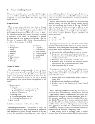
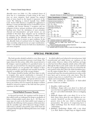
The stress distribution in the vessel wall of a thick-walled
vessel varies across the section. This is also true for thin-
walled vessels, but for purposes of analysis the stress is
considered uniform since the difference between the inner
and outer surface is slight. A visual comparison is offered
in Figure 1-3.
Thermal Stresses
Whenever the expansion or contraction that would occur
normally as a result of heating or cooling an object is
prevented, thermal stresses are developed. The stress is
always caused by some form of mechanical restraint.
A
B
Figure 1-3. Comparision of stress distribution between thin-walled (A)
and thick-walled (B) vessels.
Stresses in Pressure Vessels 11
12. Thermal stresses are ‘‘secondary stresses’’ because they
are self-limiting. That is, yielding or deformation of the
part relaxes the stress (except thermal stress ratcheting).
Thermal stresses will not cause failure by rupture in
ductile materials except by fatigue over repeated applica-
tions. They can, however, cause failure due to excessive
deformations.
Mechanical restraints are either internal or external.
External restraint occurs when an object or component is
supported or contained in a manner that restricts thermal
movement. An example of external restraint occurs when
piping expands into a vessel nozzle creating a radial load
on the vessel shell. Internal restraint occurs when the tem-
perature through an object is not uniform. Stresses from
a ‘‘thermal gradient’’ are due to internal restraint. Stress is
caused by a thermal gradient whenever the temperature dis-
tribution or variation within a member creates a differential
expansion such that the natural growth of one fiber is
influenced by the different growth requirements of adjacent
fibers. The result is distortion or warpage.
A transient thermal gradient occurs during heat-up and
cool-down cycles where the thermal gradient is changing
with time.
Thermal gradients can be logarithmic or linear across a
vessel wall. Given a steady heat input inside or outside a tube
the heat distribution will be logarithmic if there is a tem-
perature difference between the inside and outside of the
tube. This effect is significant for thick-walled vessels. A
linear temperature distribution occurs if the wall is thin.
Stress calculations are much simpler for linear distribution.
Thermal stress ratcheting is progressive incremental
inelastic deformation or strain that occurs in a component
that is subjected to variations of mechanical and thermal
stress. Cyclic strain accumulation ultimately can lead to
incremental collapse. Thermal stress ratcheting is the result
of a sustained load and a cyclically applied temperature
distribution.
The fundamental difference between mechanical stresses
and thermal stresses lies in the nature of the loading. Thermal
stresses as previously stated are a result of restraint or tem-
perature distribution. The fibers at high temperature are
compressed and those at lower temperatures are stretched.
The stress pattern must only satisfy the requirements for
equilibrium of the internal forces. The result being that
yielding will relax the thermal stress. If a part is loaded
mechanically beyond its yield strength, the part will continue
to yield until it breaks, unless the deflection is limited by
strain hardening or stress redistribution. The external load
remains constant, thus the internal stresses cannot relax.
The basic equations for thermal stress are simple but
become increasingly complex when subjected to variables
such as thermal gradients, transient thermal gradients,
logarithmic gradients, and partial restraint. The basic equa-
tions follow. If the temperature of a unit cube is changed
from T1 to T2 and the growth of the cube is fully
restrained:
where T1 ¼ initial temperature,
F
T2 ¼ new temperature,
F
¼ mean coefficient of thermal expansion in./in./
F
E ¼ modulus of elasticity, psi
v ¼ Poisson’s ratio ¼ .3 for steel
T ¼ mean temperature difference,
F
Case 1: If the bar is restricted only in one direction but free
to expand in the other direction, the resulting uniaxial
stress, , would be
¼ EðT2 T1Þ
. If T2 T1, is compressive (expansion).
. If T1 T2, is tensile (contraction).
Case 2: If restraint is in both directions, x and y, then:
x ¼ y ¼ E T=1 v
Case 3: If restraint is in all three directions, x, y, and z, then
x ¼ y ¼ z ¼ E T=1 2v
Case 4: If a thermal linear gradient is across the wall of a
thin shell (see Figure 1–4), then:
x ¼ ¼ E T=2ð1 vÞ
This is a bending stress and not a membrane stress. The hot
side is in tension, the cold side in compression. Note that this
is independent of vessel diameter or thickness. The stress is
due to internal restraint.
Discontinuity Stresses
Vessel sections of different thickness, material, diameter,
and change in directions would all have different displace-
ments if allowed to expand freely. However, since they
are connected in a continuous structure, they must deflect
and rotate together. The stresses in the respective parts at or
near the juncture are called discontinuity stresses. Disconti-
nuity stresses are necessary to satisfy compatibility of defor-
mation in the region. They are local in extent but can be of
TC
TH
∆T
Figure 1-4. Thermal linear gradient across shell wall.
12 Pressure Vessel Design Manual
13. very high magnitude. Discontinuity stresses are ‘‘secondary
stresses’’ and are self-limiting. That is, once the structure
has yielded, the stresses are reduced. In average application
they will not lead to failure. Discontinuity stresses do
become an important factor in fatigue design where cyclic
loading is a consideration. Design of the juncture of the
two parts is a major consideration in reducing discontinuity
stresses.
In order to find the state of stress in a pressure vessel, it is
necessary to find both the membrane stresses and the dis-
continuity stresses. From superposition of these two states
of stress, the total stresses are obtained. Generally when
combined, a higher allowable stress is permitted. Due to
the complexity of determining discontinuity stress, solutions
will not be covered in detail here. The designer should be
aware that for designs of high pressure (1,500 psi), brittle
material or cyclic loading, discontinuity stresses may be a
major consideration.
Since discontinuity stresses are self-limiting, allowable
stresses can be very high. One example specifically
addressed by the ASME Code, Section VIII, Division 1,
is discontinuity stresses at cone-cylinder intersections
where the included angle is greater than 60
. Para. 1-5(e)
recommends limiting combined stresses (membrane þ dis-
continuity) in the longitudinal direction to 4SE and in the
circumferential direction to 1.5SE.
ASME Code, Section VIII, Division 2, limits the com-
bined stress, primary membrane and discontinuity stresses
to 3Sm, where Sm is the lesser of 2
⁄3Fy or 1
⁄3U.T.S., whichever
is lower.
There are two major methods for determining dis-
continuity stresses:
1. Displacement Method—Conditions of equilibrium are
expressed in terms of displacement.
2. Force Method—Conditions of compatibility of dis-
placements are expressed in terms of forces.
See References 2, Article 4–7; 6, Chapter 8; and 7,
Chapter 4 for detailed information regarding calculation of
discontinuity stresses.
Fatigue Analysis
ASME Code, Section VIII, Division 1, does not speci-
fically provide for design of vessels in cyclic service.
Although considered beyond the scope of this text as well,
the designer must be aware of conditions that would require
a fatigue analysis to be made.
When a vessel is subject to repeated loading that could
cause failure by the development of a progressive fracture,
the vessel is in cyclic service. ASME Code, Section VIII,
Division 2, has established specific criteria for determining
when a vessel must be designed for fatigue.
It is recognized that Code formulas for design of details,
such as heads, can result in yielding in localized regions.
Thus localized stresses exceeding the yield point may be
encountered even though low allowable stresses have been
used in the design. These vessels, while safe for relatively
static conditions of loading, would develop ‘‘progressive frac-
ture’’ after a large number of repeated loadings due to these
high localized and secondary bending stresses. It should be
noted that vessels in cyclic service require special considera-
tion in both design and fabrication.
Fatigue failure can also be a result of thermal variations as
well as other loadings. Fatigue failure has occurred in boiler
drums due to temperature variations in the shell at the feed
water inlet. In cases such as this, design details are of
extreme importance.
Behavior of metal under fatigue conditions varies signifi-
cantly from normal stress-strain relationships. Damage
accumulates during each cycle of loading and develops at
localized regions of high stress until subsequent repetitions
finally cause visible cracks to grow, join, and spread. Design
details play a major role in eliminating regions of stress
raisers and discontinuities. It is not uncommon to have
the design strength cut in half by poor design details.
Progressive fractures develop from these discontinuities
even though the stress is well below the static elastic strength
of the material.
In fatigue service the localized stresses at abrupt changes
in section, such as at a head junction or nozzle opening,
misalignment, defects in construction, and thermal gradients
are the significant stresses.
The determination of the need for a fatigue evaluation is
in itself a complex job best left to those experienced in this
type of analysis. For specific requirements for determining if
a fatigue analysis is required see ASME Code, Section VIII,
Division 2, Para. AD-160.
For additional information regarding designing pressure
vessels for fatigue see Reference 7, Chapter 5.
Stresses in Pressure Vessels 13
14. REFERENCES
1. ASME Boiler and Pressure Vessel Code, Section VIII,
Division 1, 1995 Edition, American Society of
Mechanical Engineers.
2. ASME Boiler and Pressure Vessel Code, Section VIII,
Division 2, 1995 Edition, American Society of
Mechanical Engineers.
3. Popov, E. P., Mechanics of Materials, Prentice Hall,
Inc., 1952.
4. Bednar, H. H., Pressure Vessel Design Handbook,
Van Nostrand Reinhold Co., 1981.
5. Harvey, J. F., Theory and Design of Modern Pressure
Vessels, Van Nostrand Reinhold Co., 1974.
6. Hicks, E. J. (Ed.), Pressure Vessels—A Workbook for
Engineers, Pressure Vessel Workshop, Energy—
Sources Technology Conference and Exhibition,
Houston, American Society of Petroleum Engineers,
January 19–21, 1981.
7. Pressure Vessel and Piping Design, Collected Papers
1927–1959, American Society of Mechanical
Engineers, 1960.
8. Brownell, L. E., and Young, E. H., Process Equipment
Design, John Wiley and Sons, 1959.
9. Roark, R. J., and Young, W. C., Formulas for Stress and
Strain, 5th Edition, McGraw Hill Book Co., 1975.
10. Burgreen, D., Design Methods for Power Plant
Structures, C. P. Press, 1975.
11. Criteria of the ASME Boiler and Pressure Vessel Code
for Design by Analysis in Sections III and VIII, Division
2, American Society of Mechanical Engineers.
14 Pressure Vessel Design Manual