This document discusses torsional stress and its effects on beams and circular shafts. It makes the following key points:
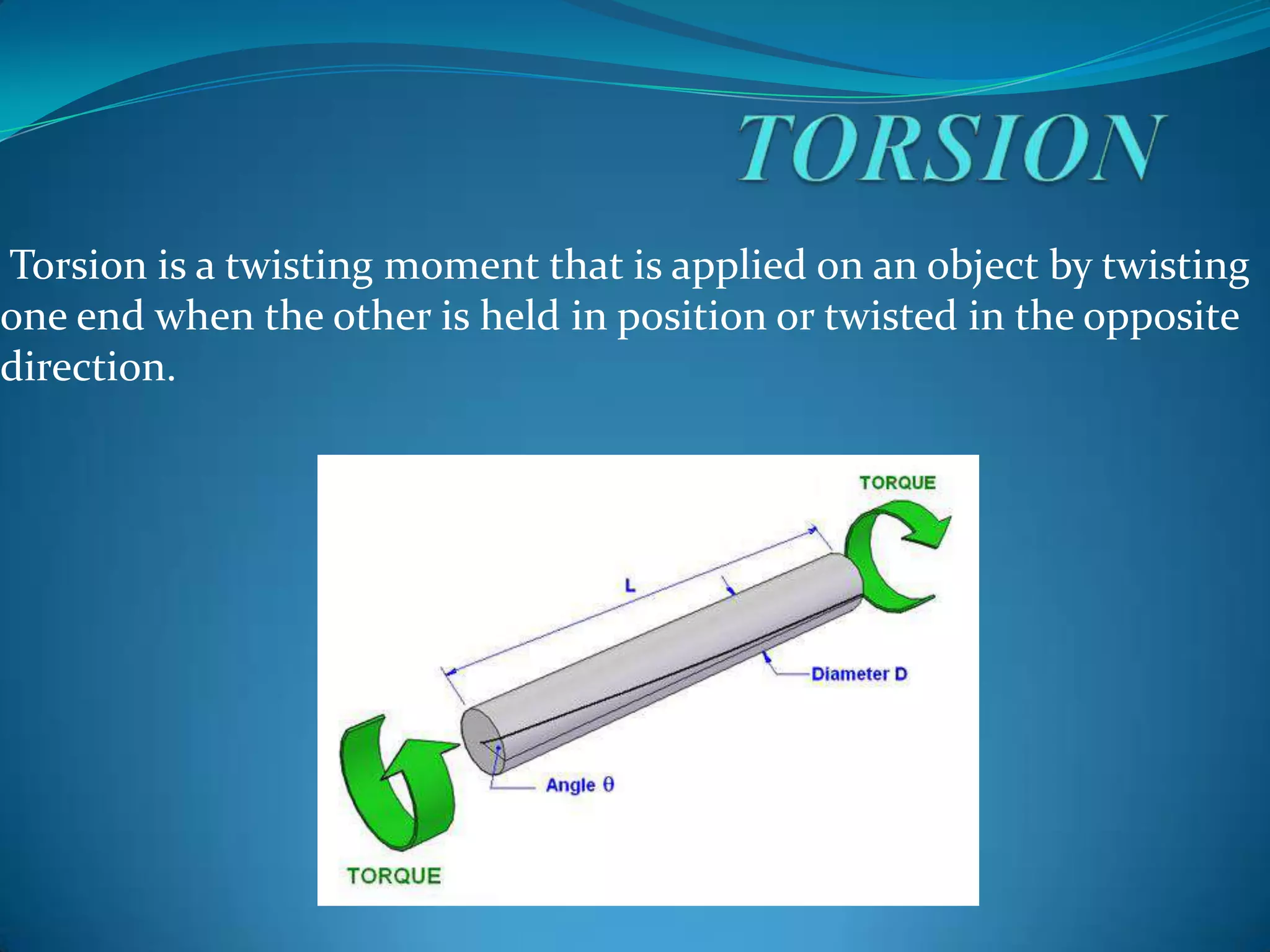
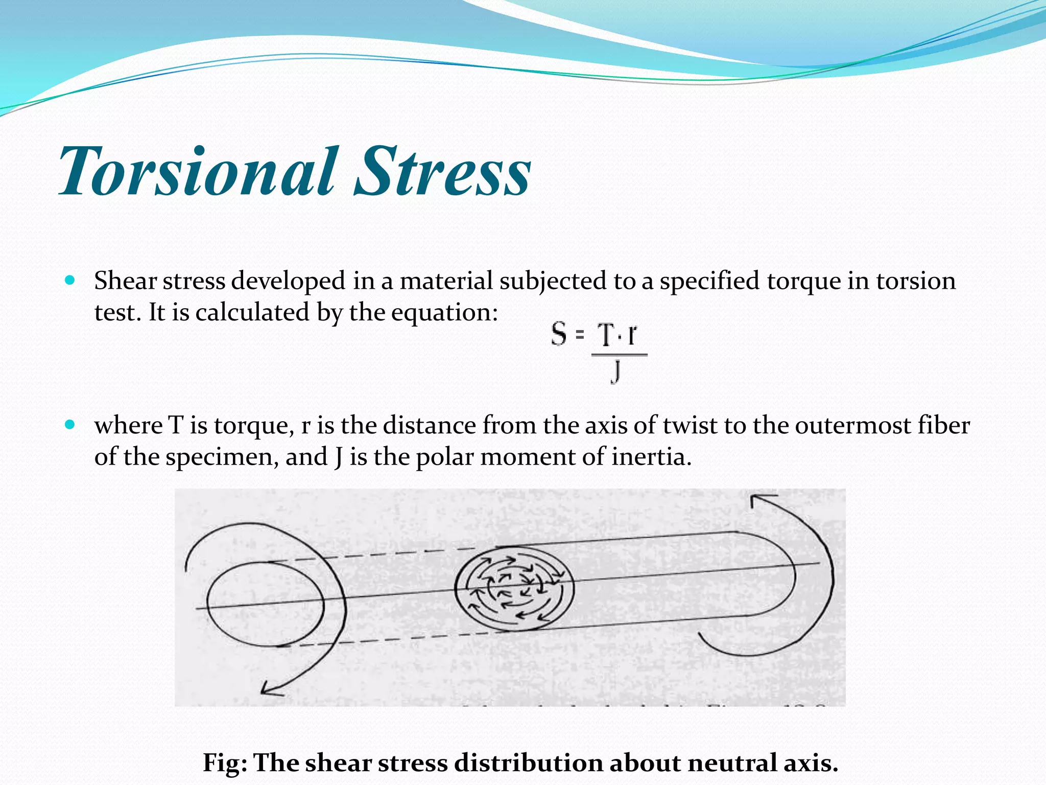
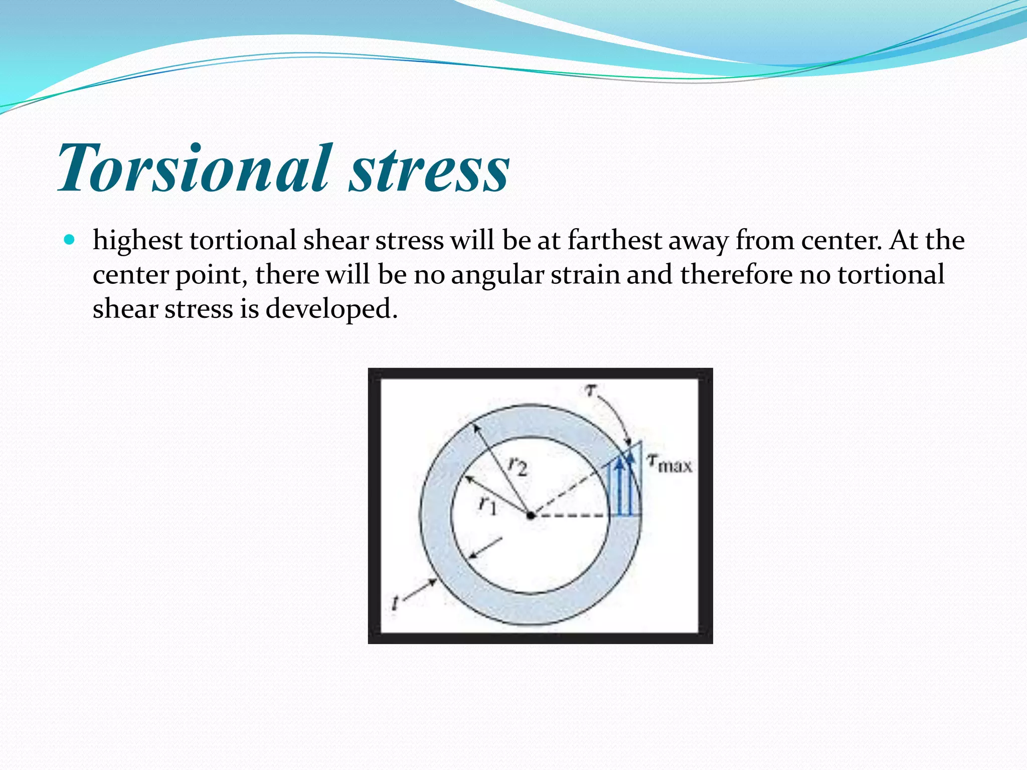
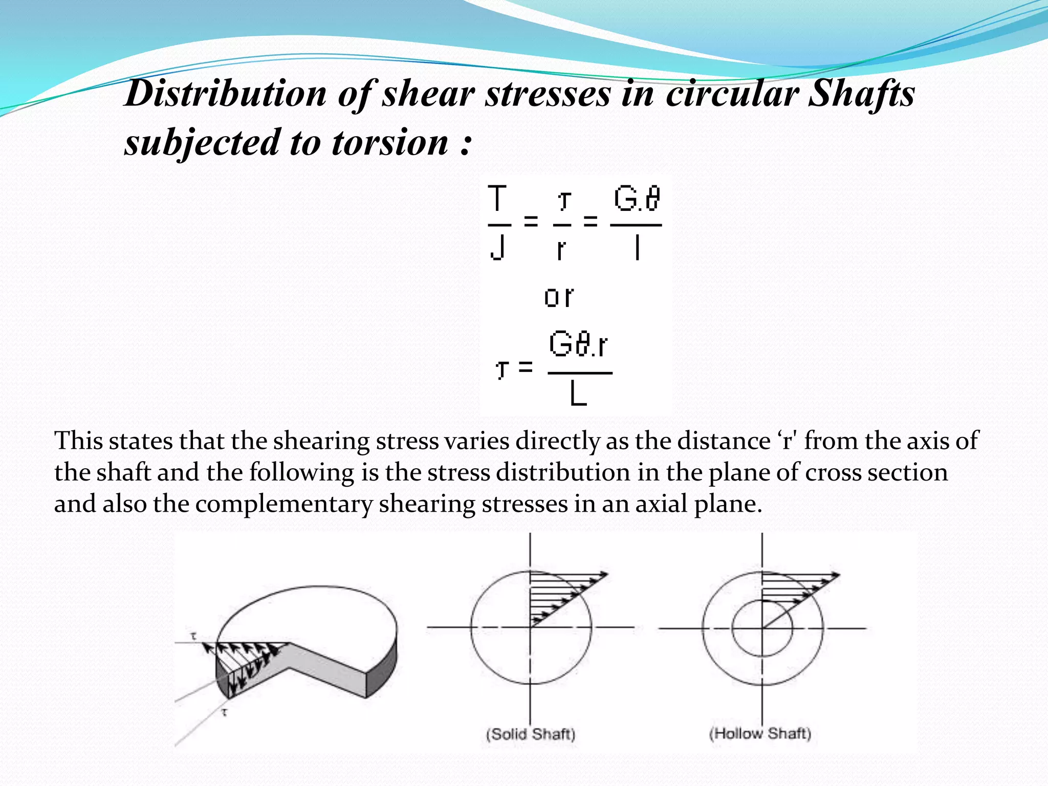
1. Torsional stress is the shear stress developed in a material subjected to a twisting torque, and is highest at the outermost parts of the material furthest from the central axis.
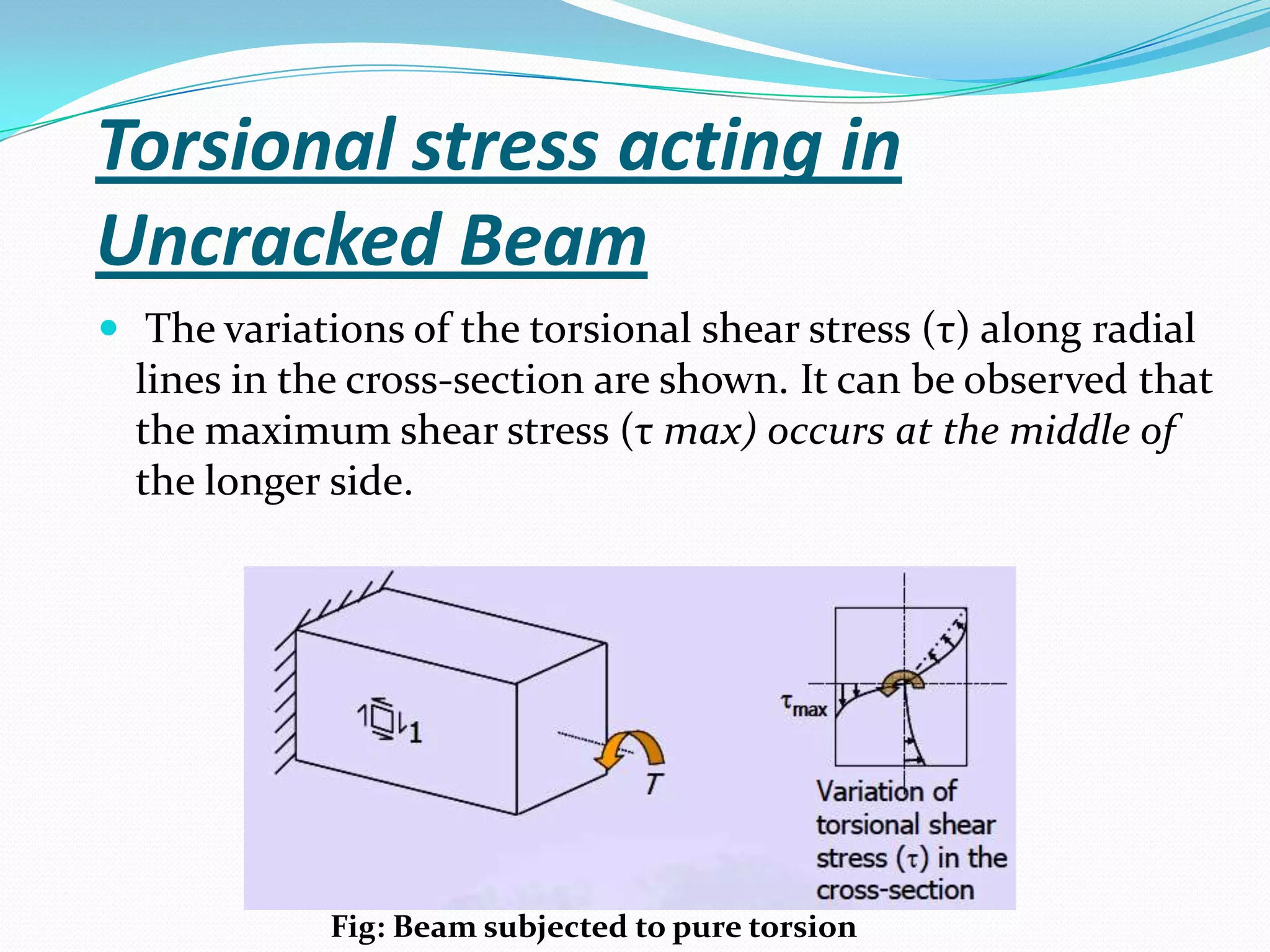
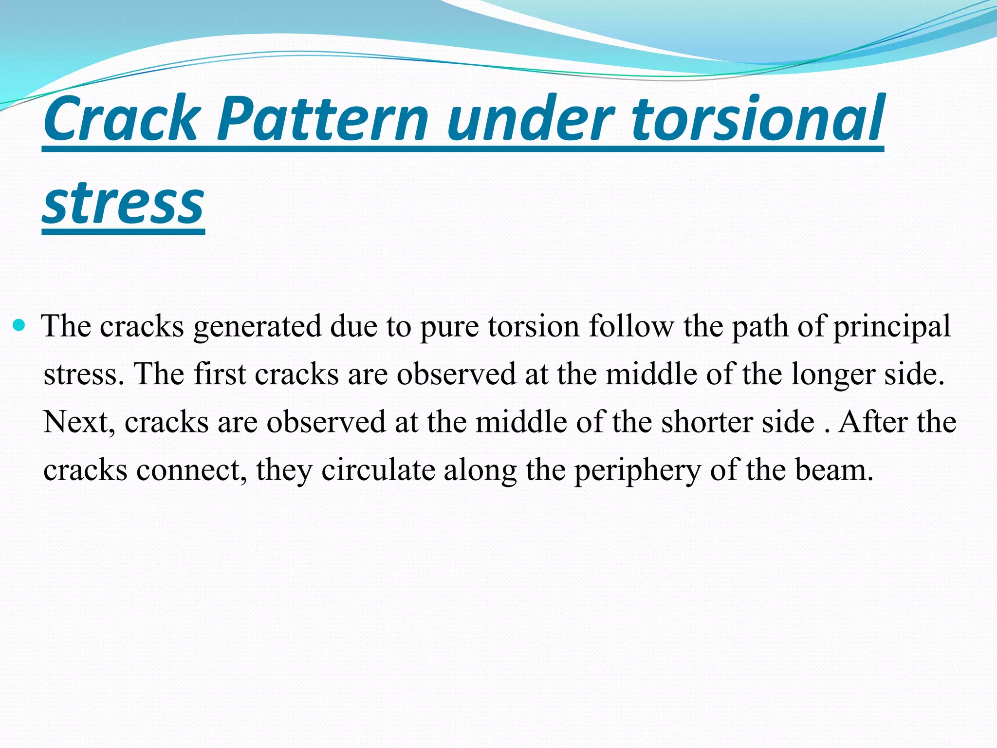
2. Cracks form under torsional stress and initially appear at the middle of the longest side of a beam, then the shortest side, before circulating around the beam's periphery.
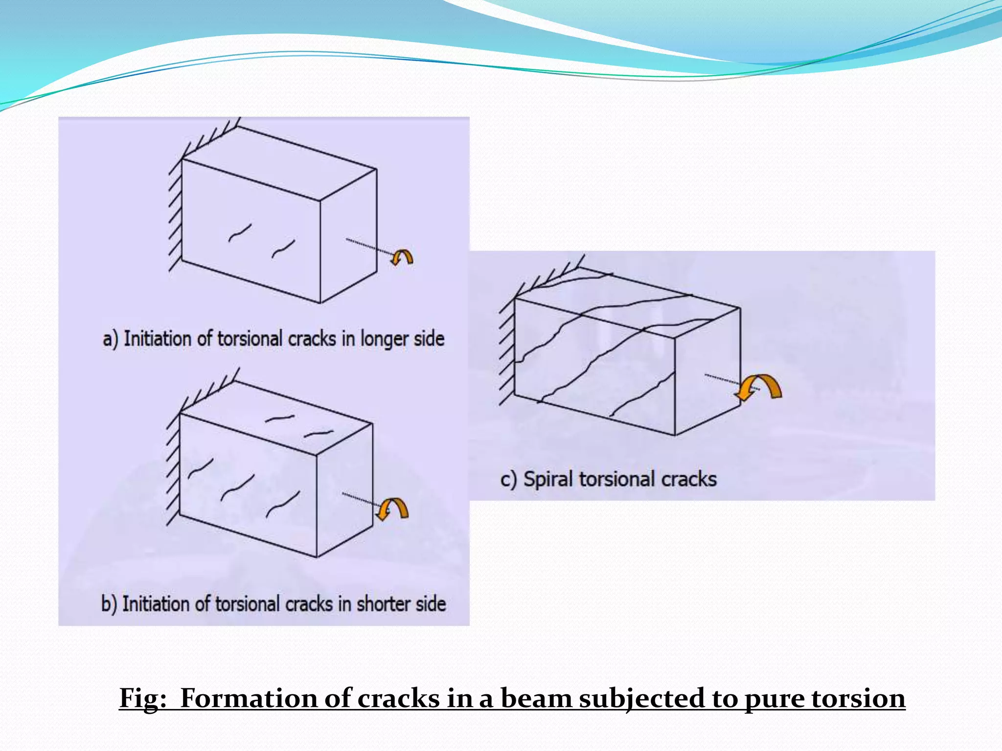
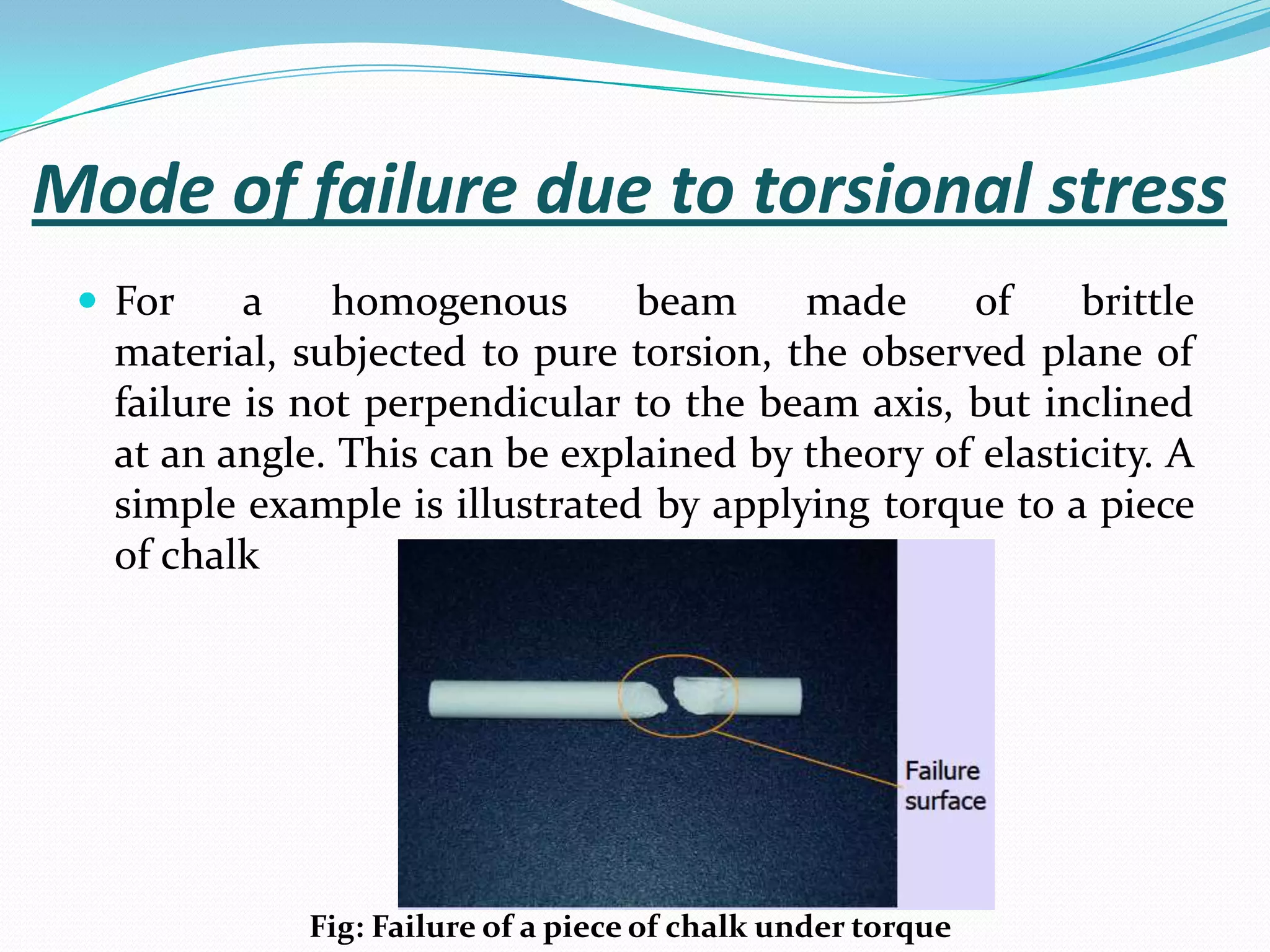
3. Failure of brittle materials under pure torsion occurs along planes inclined to the beam axis, not perpendicular, due to elastic theory principles.