Downloaded 2,714 times
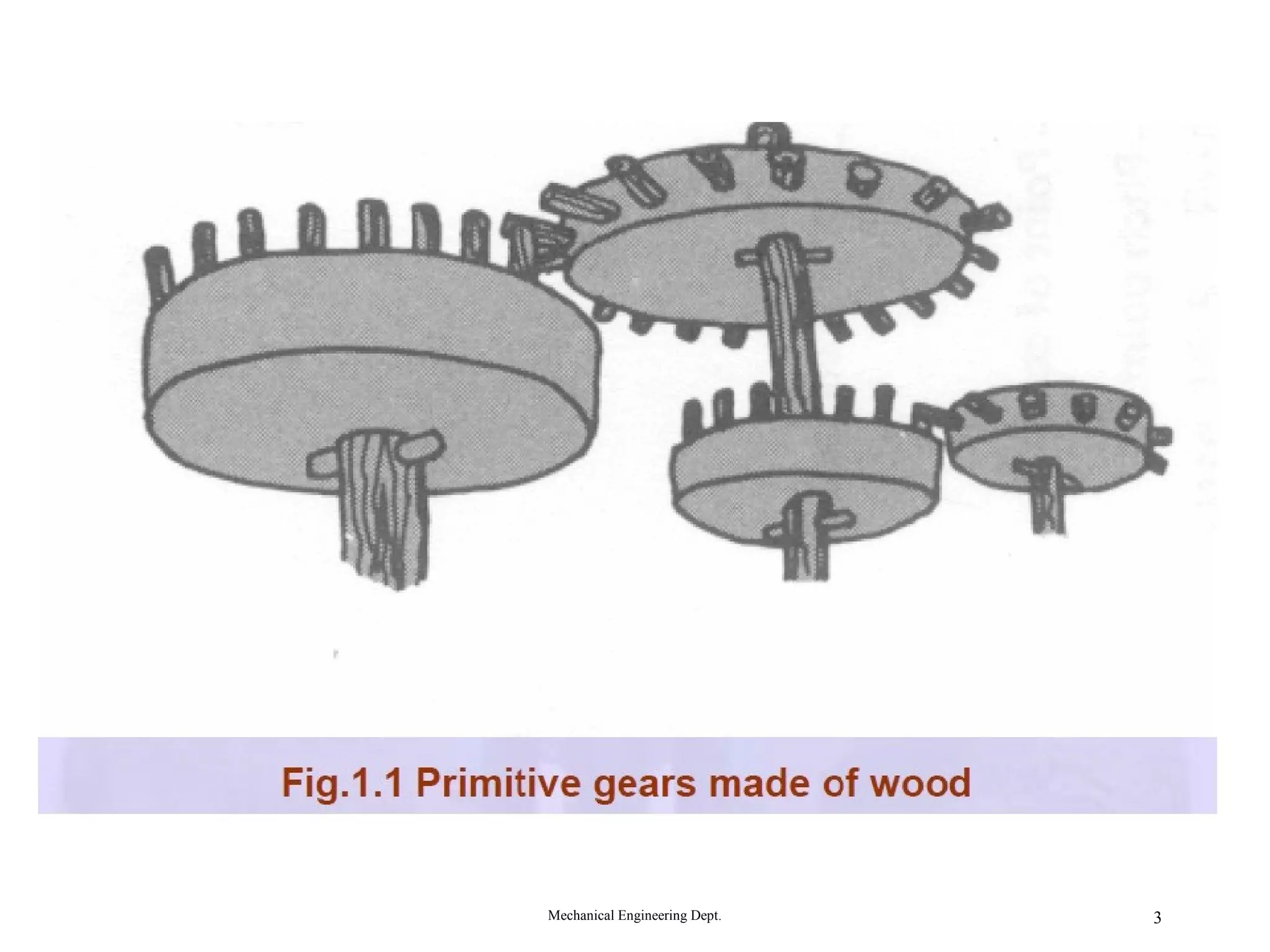
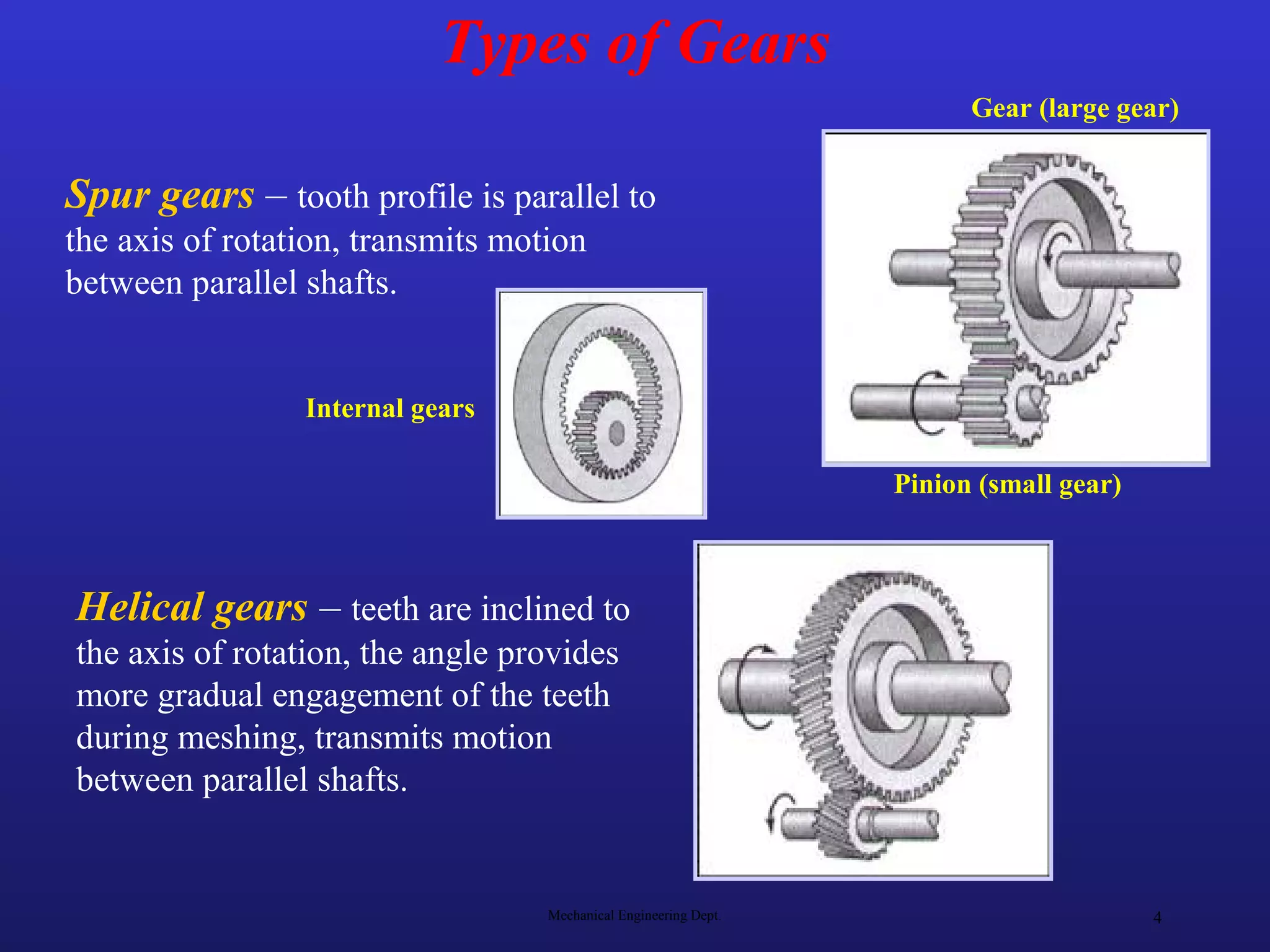
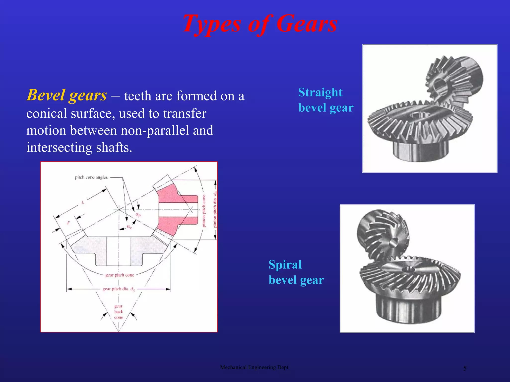
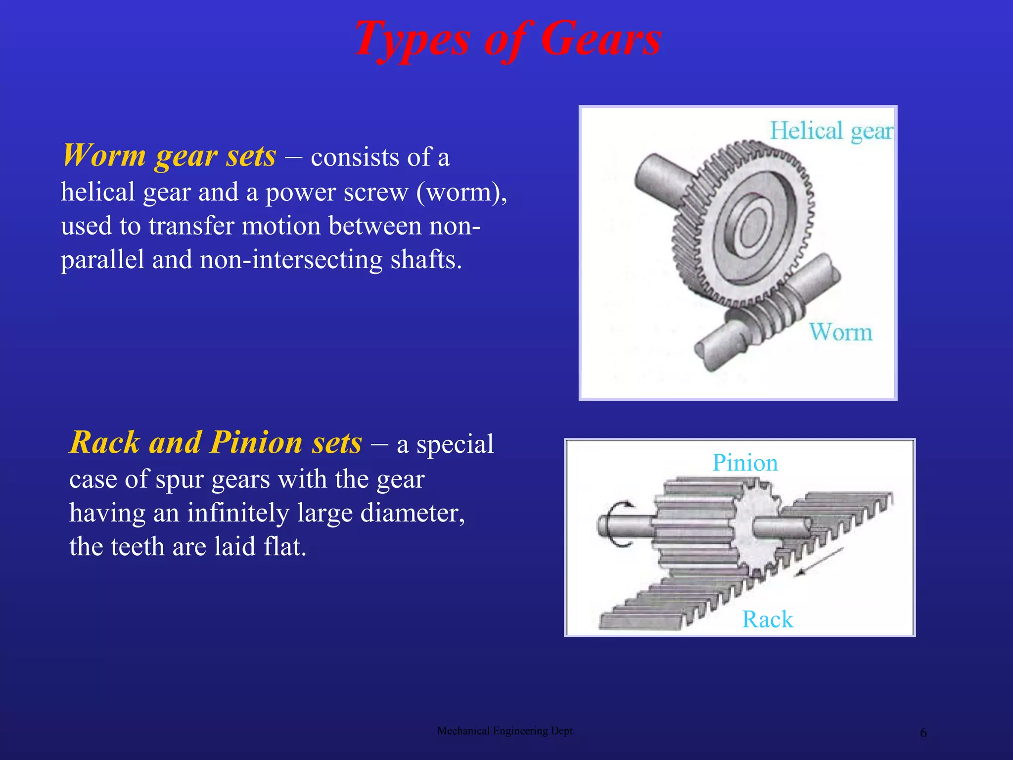
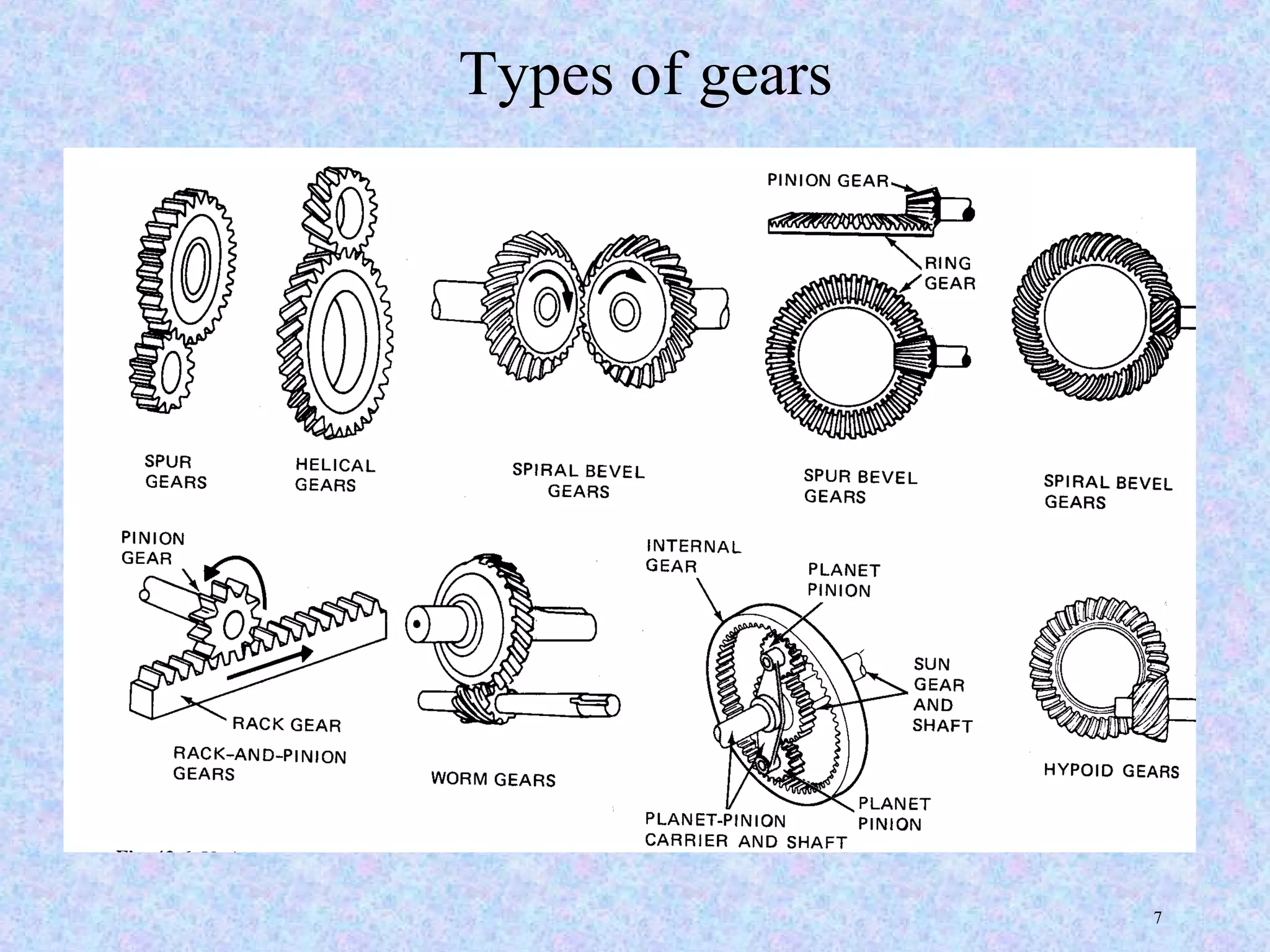
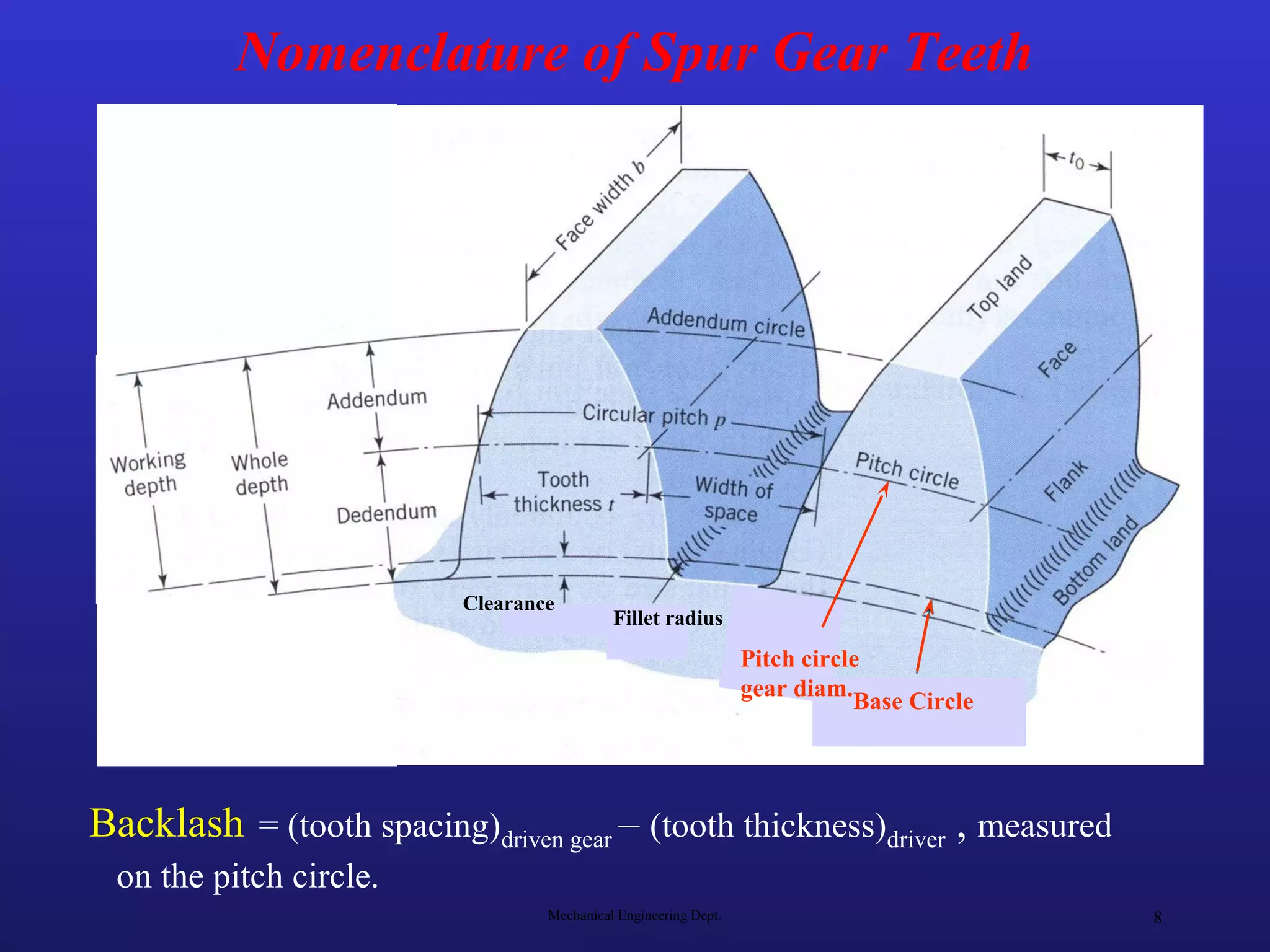
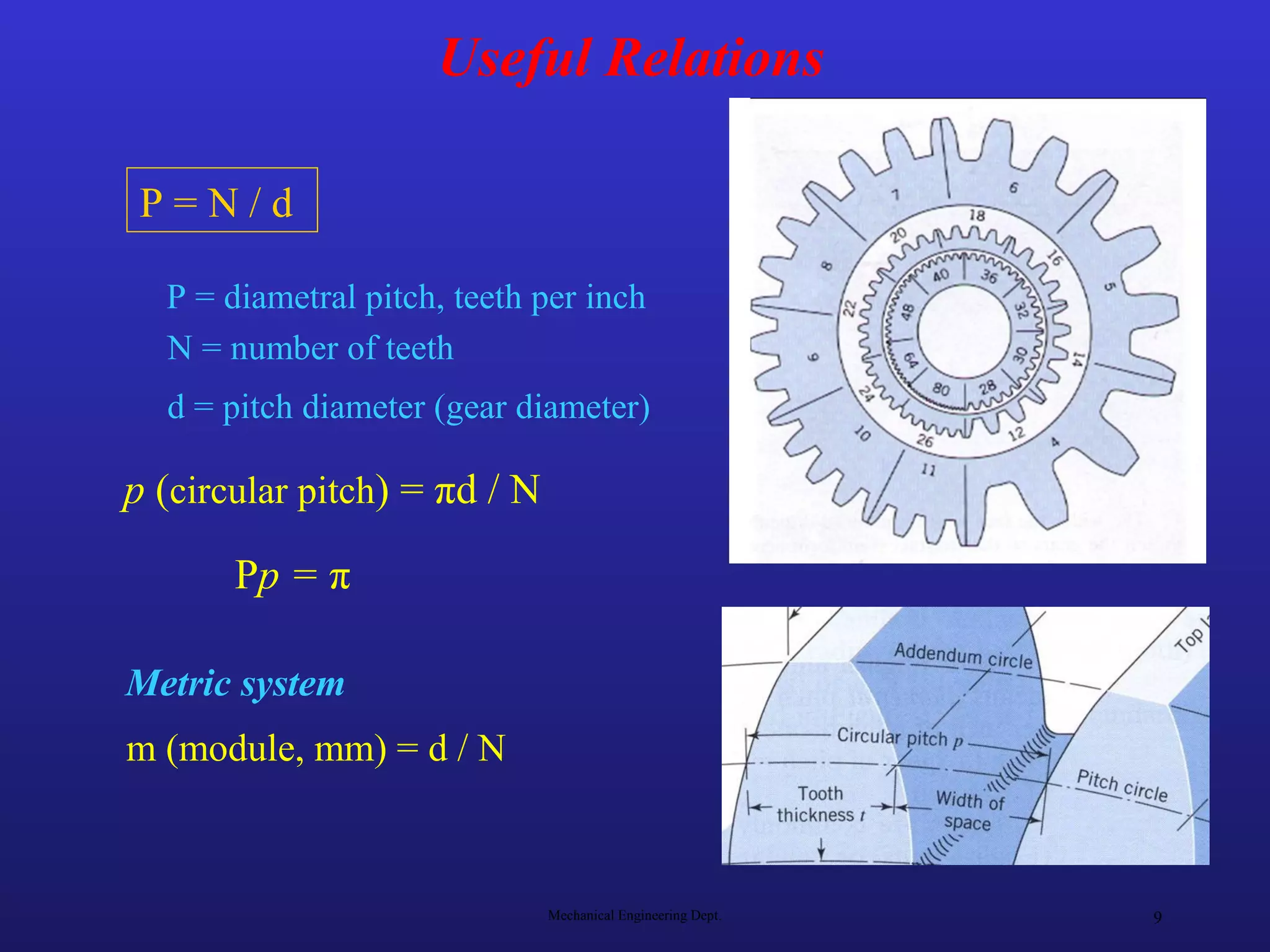
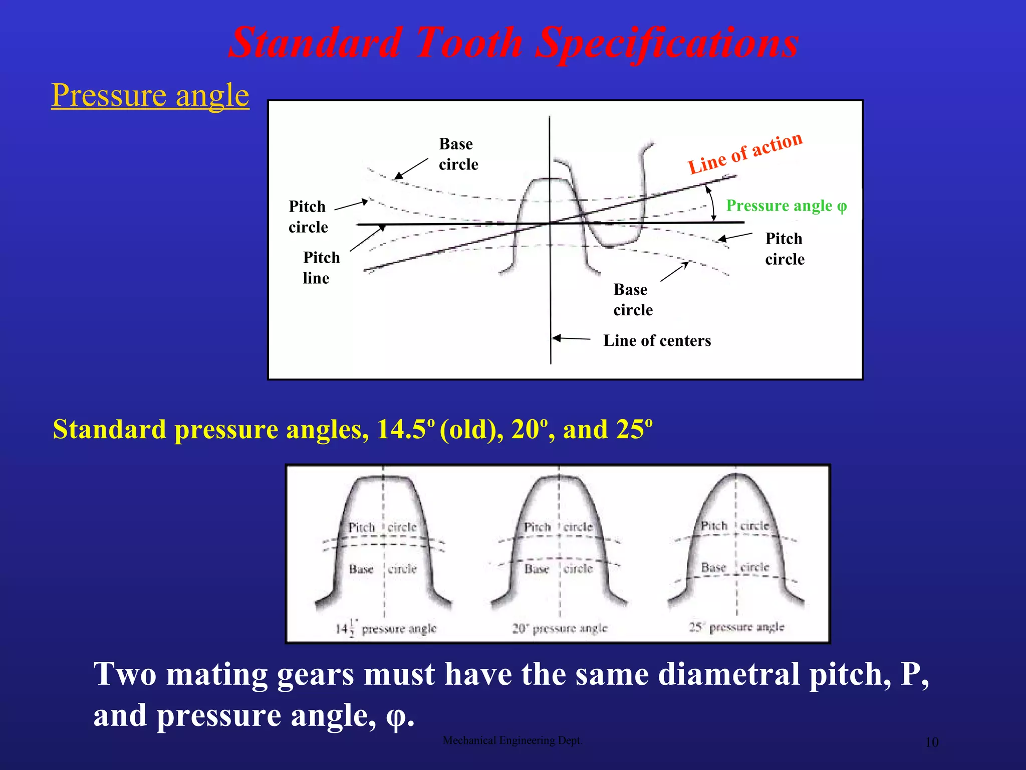
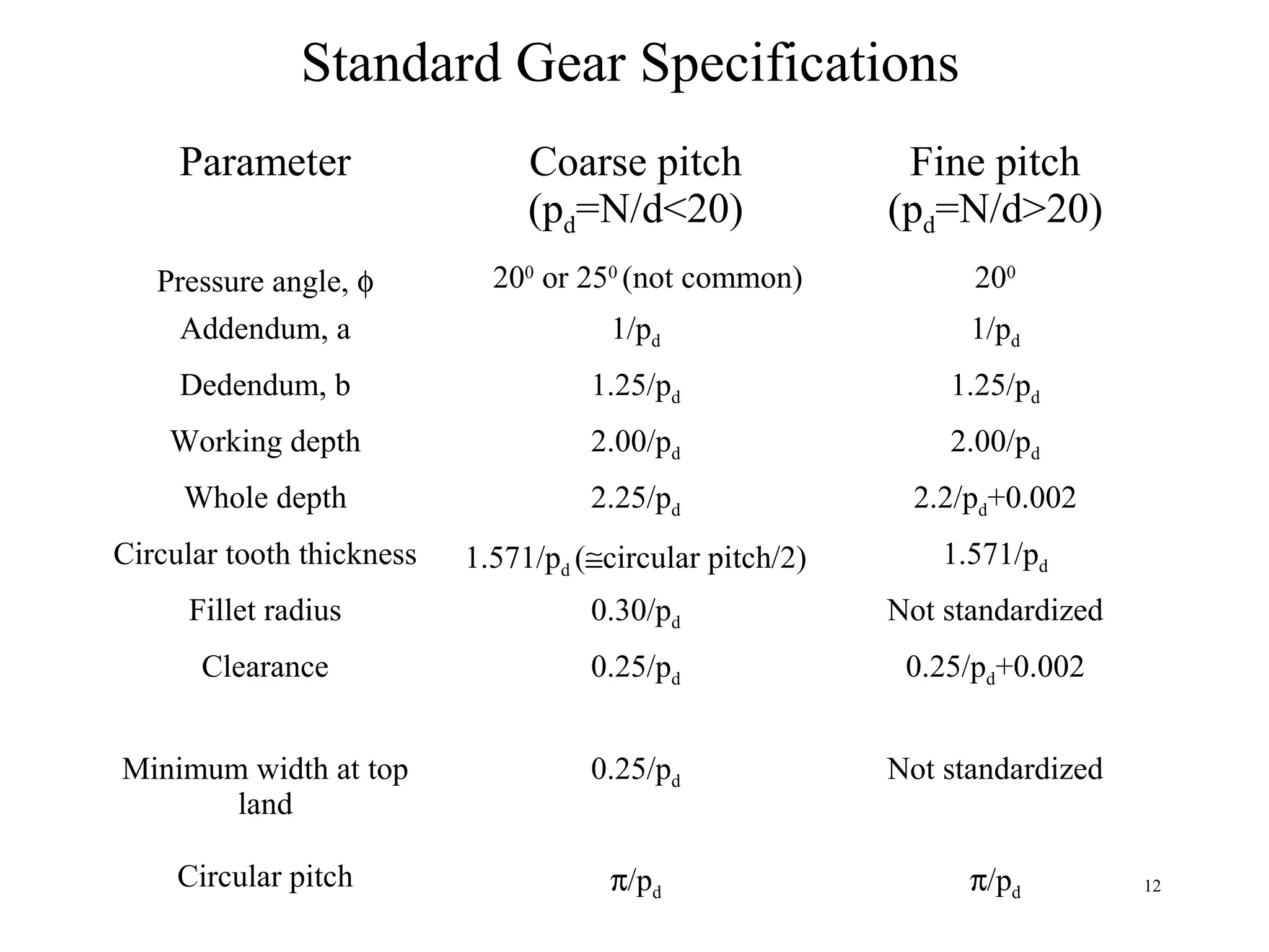
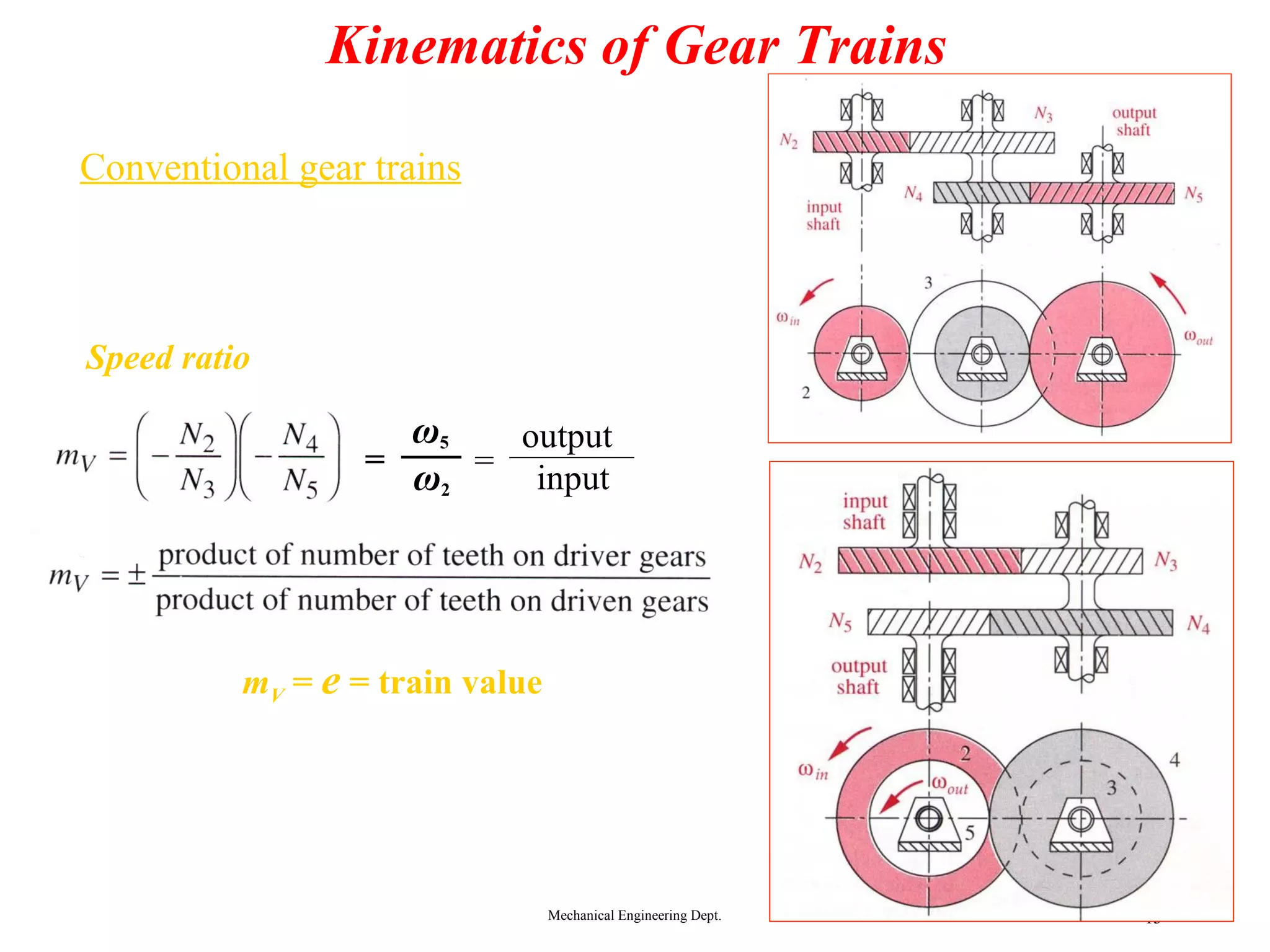
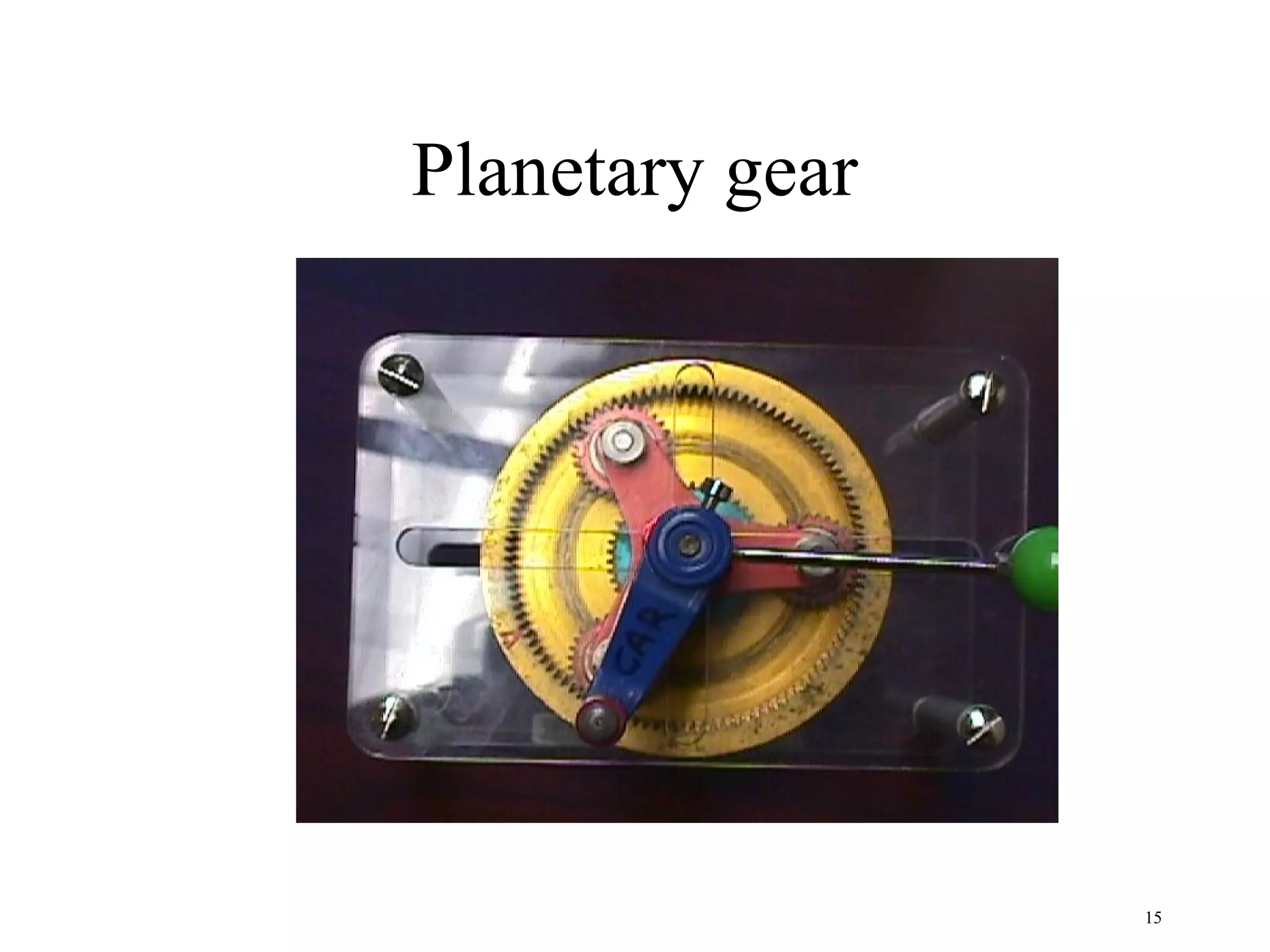
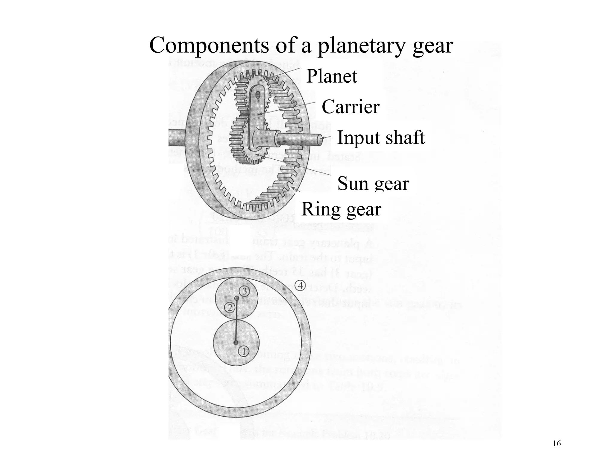
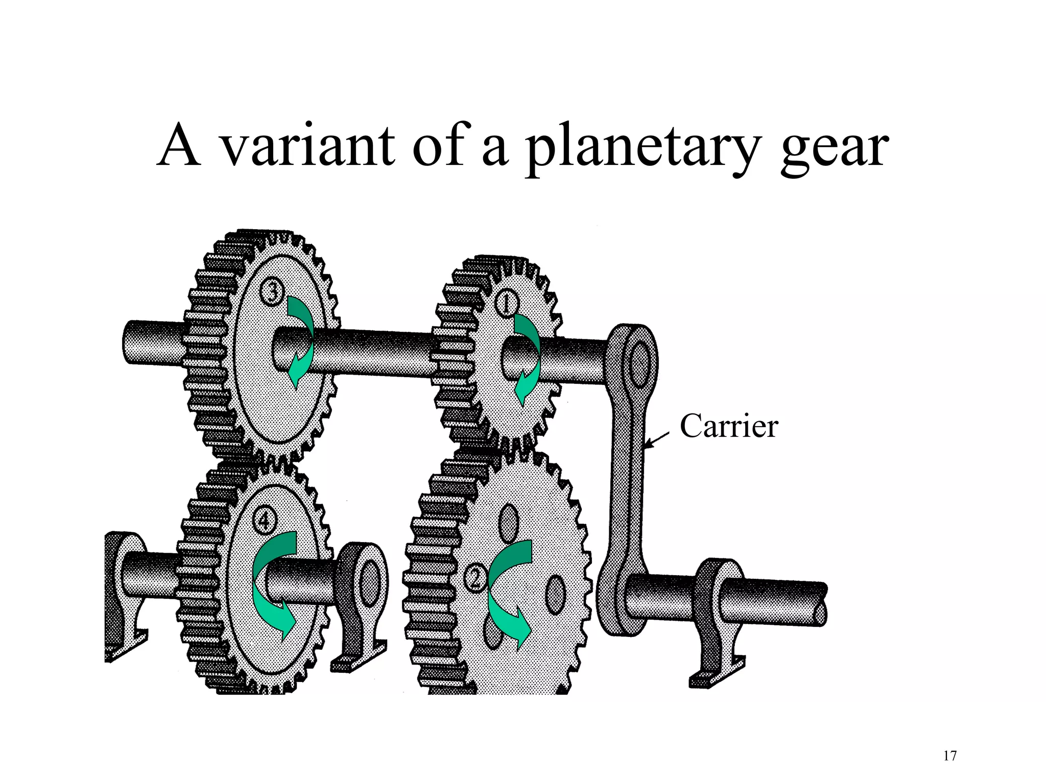
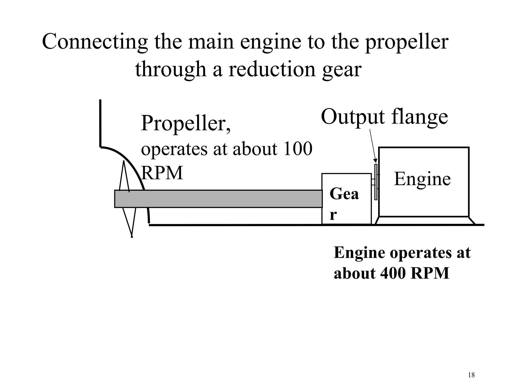
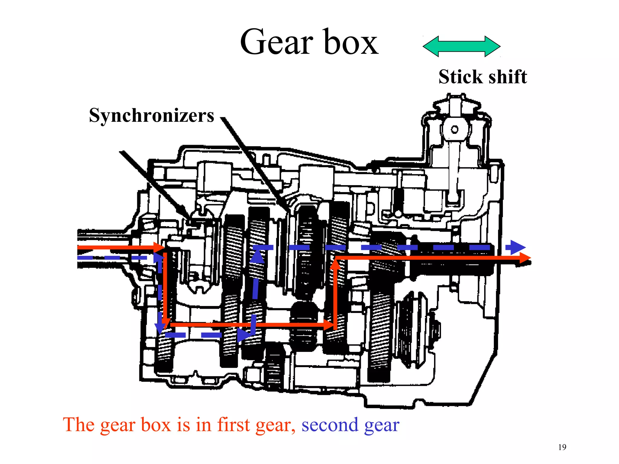
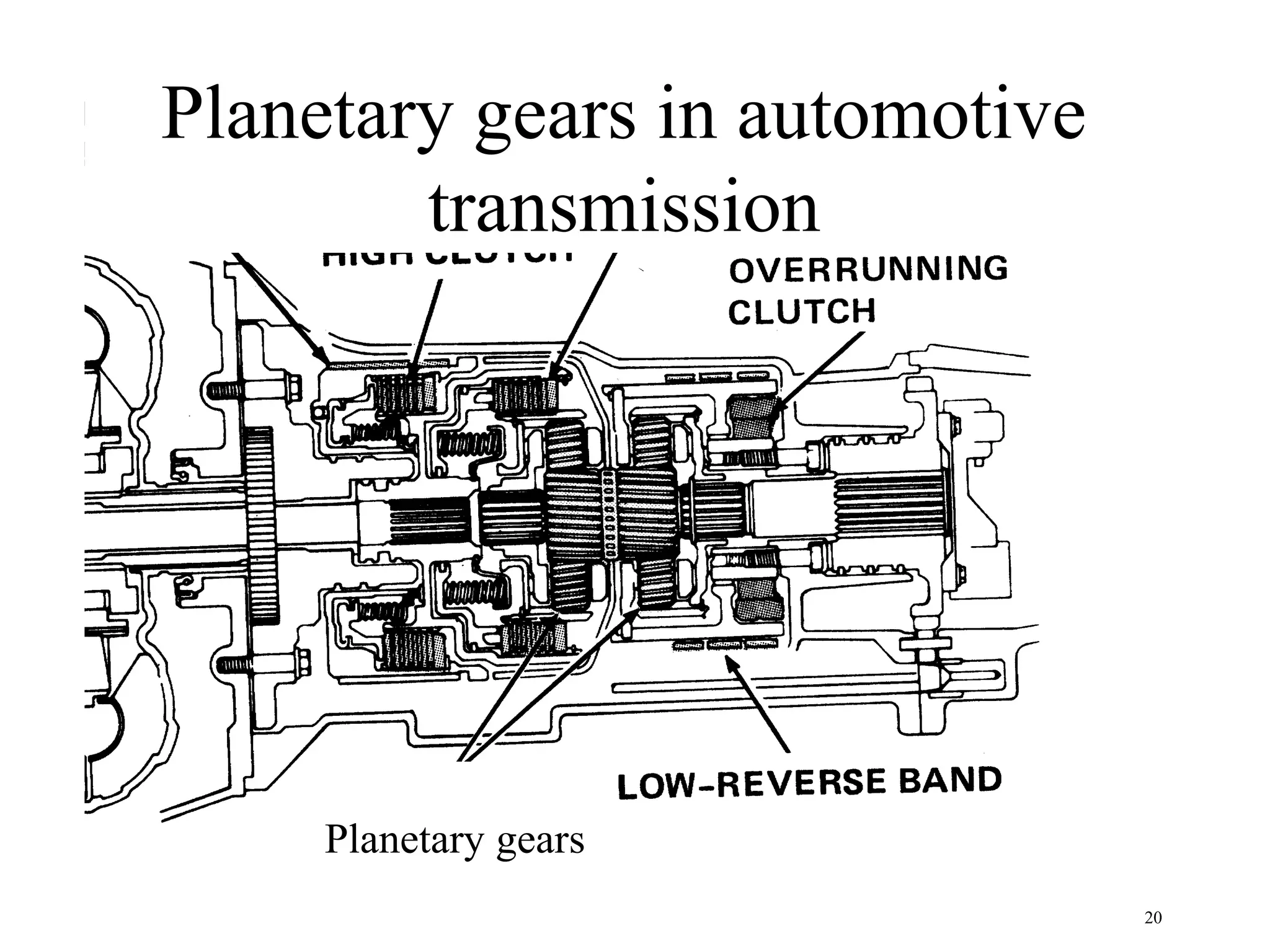

Gears are used to transmit motion between rotating shafts and can change the speed and torque characteristics. The document discusses various types of gears including spur gears, helical gears, bevel gears, worm gears, and rack and pinion gears. It also covers planetary or epicyclic gears which are used in automatic transmissions to achieve large speed reductions in a compact space. Standard specifications for parameters like pressure angle, addendum, dedendum, and circular pitch are provided for designing gear teeth.