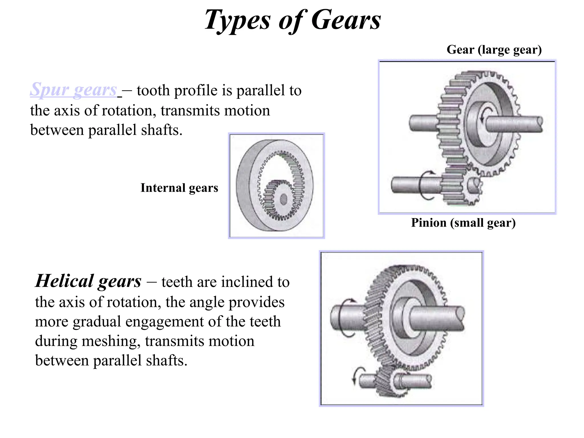
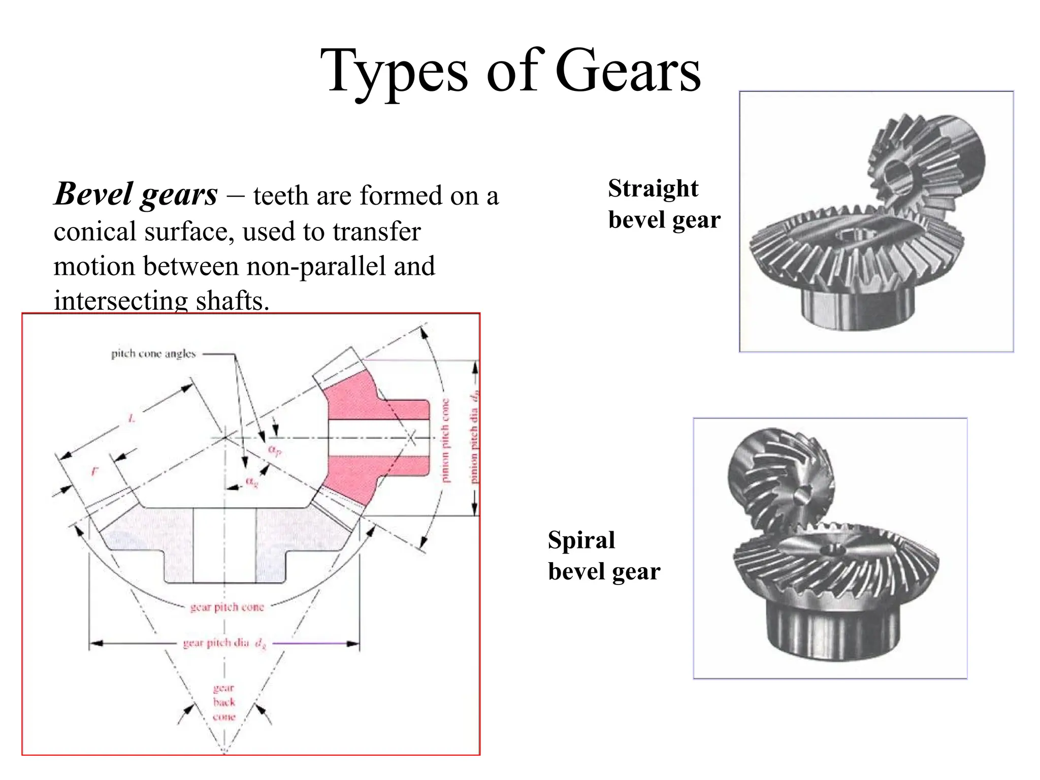
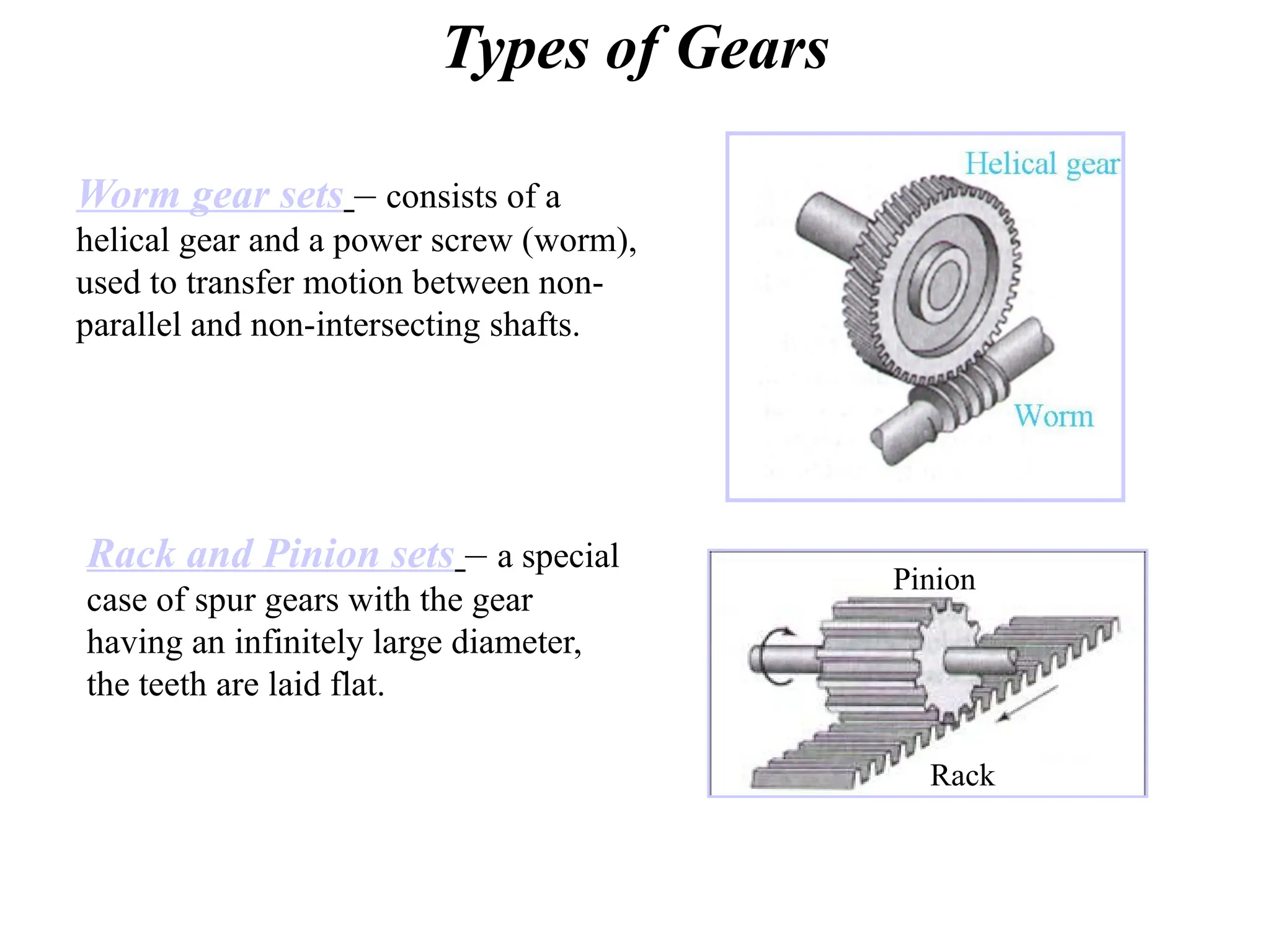
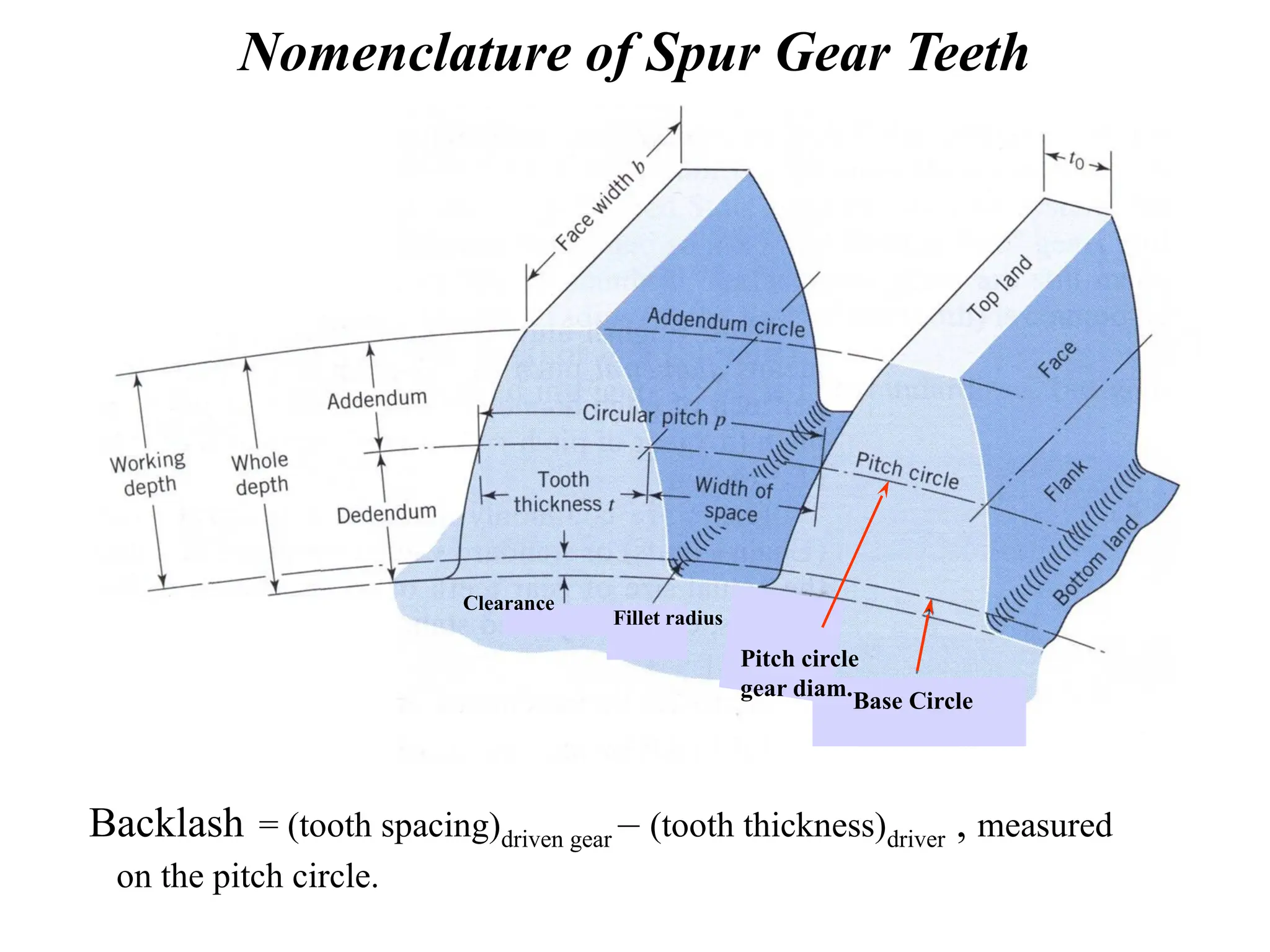
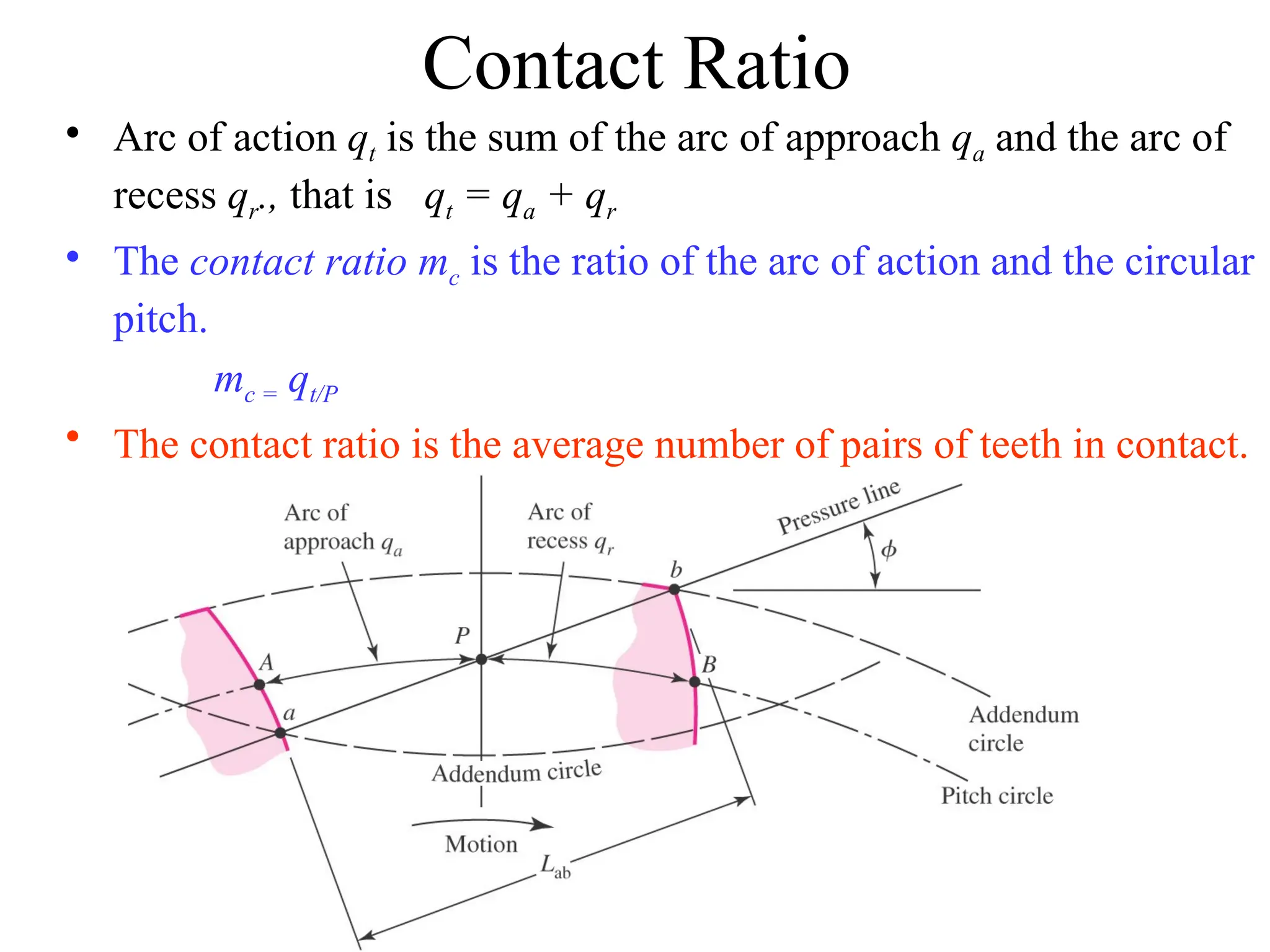
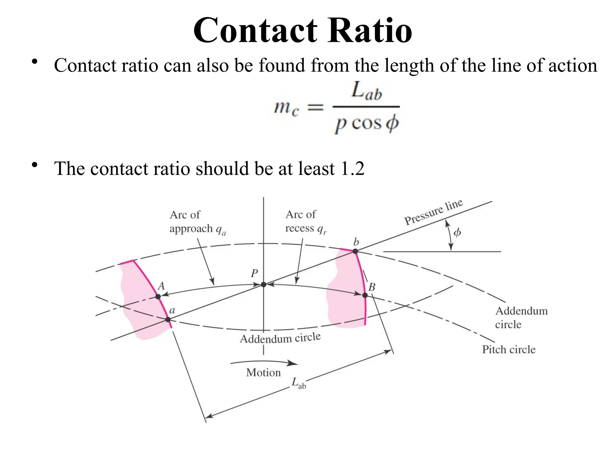
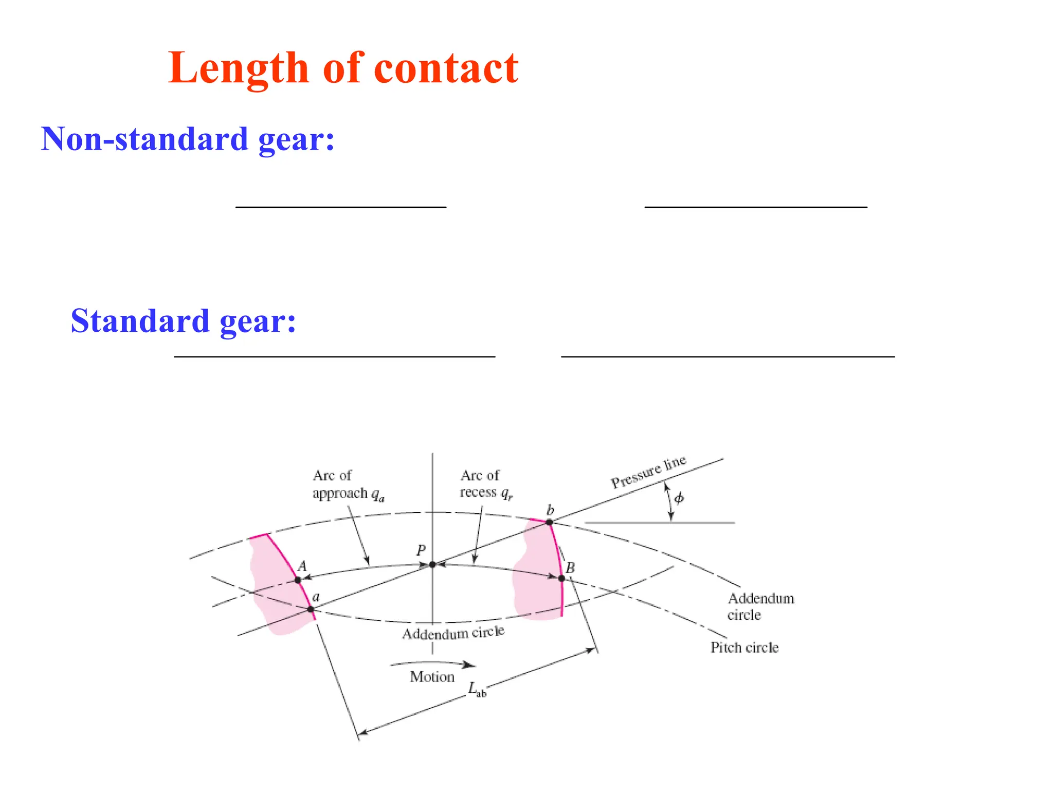
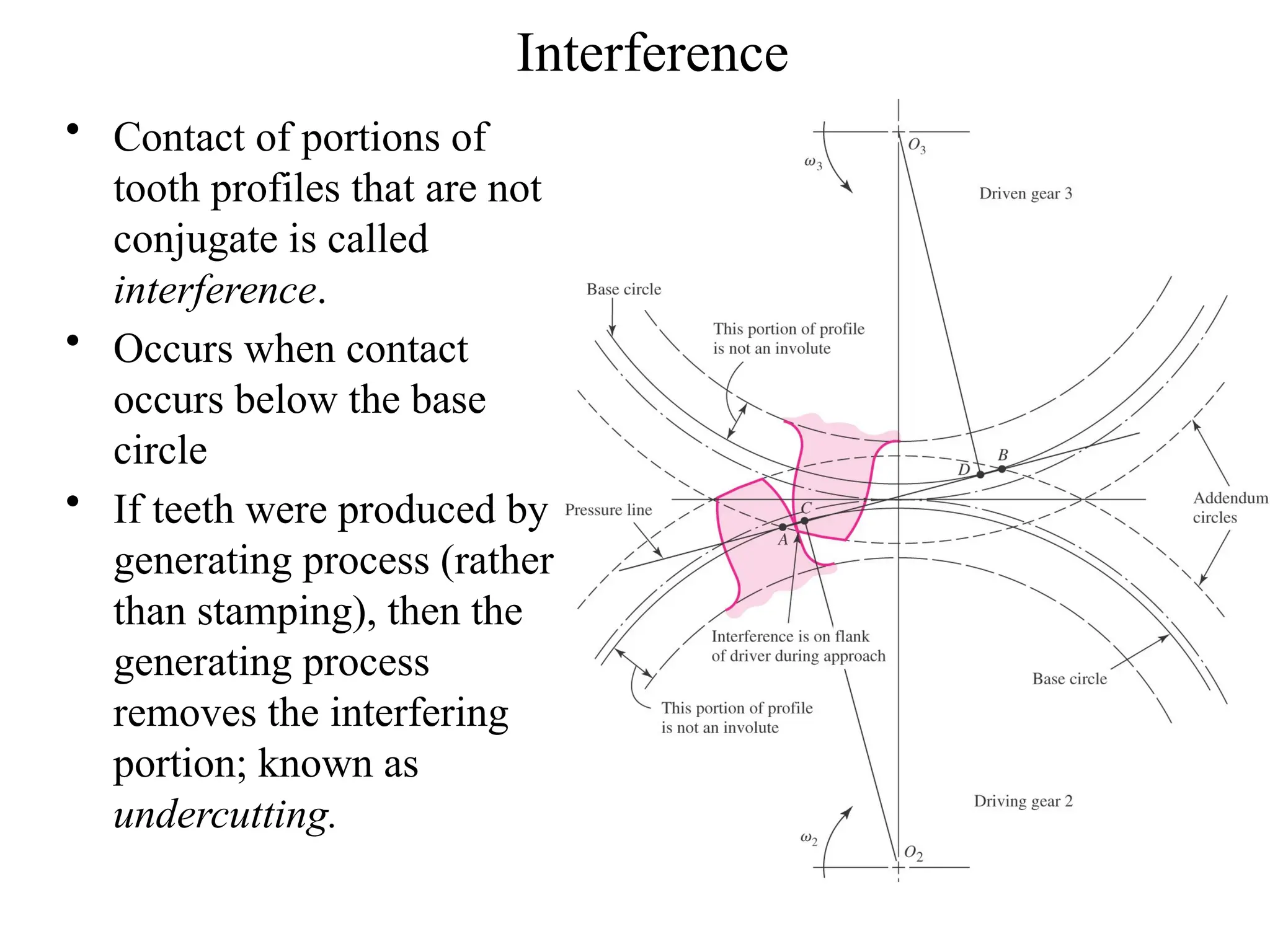
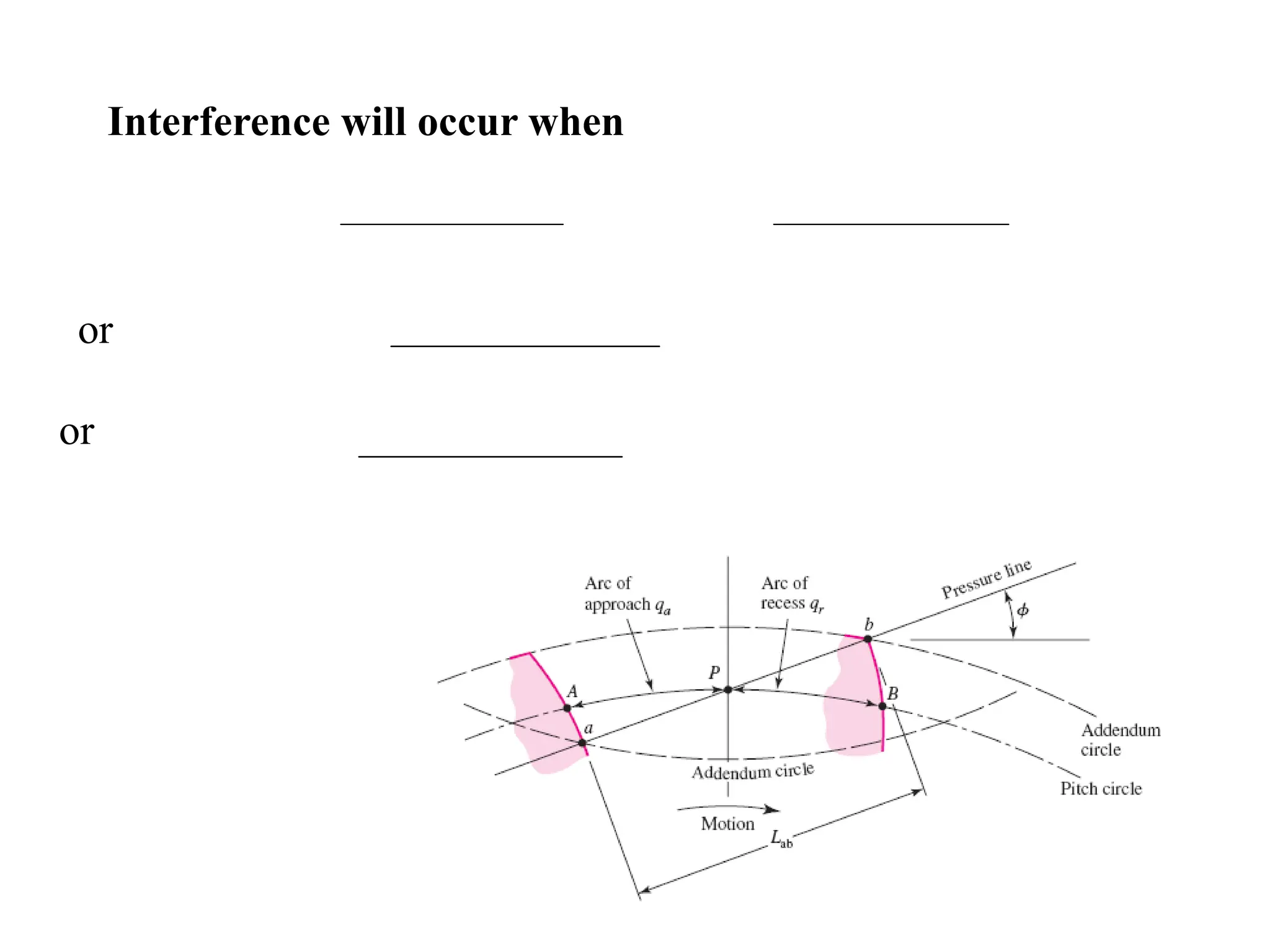
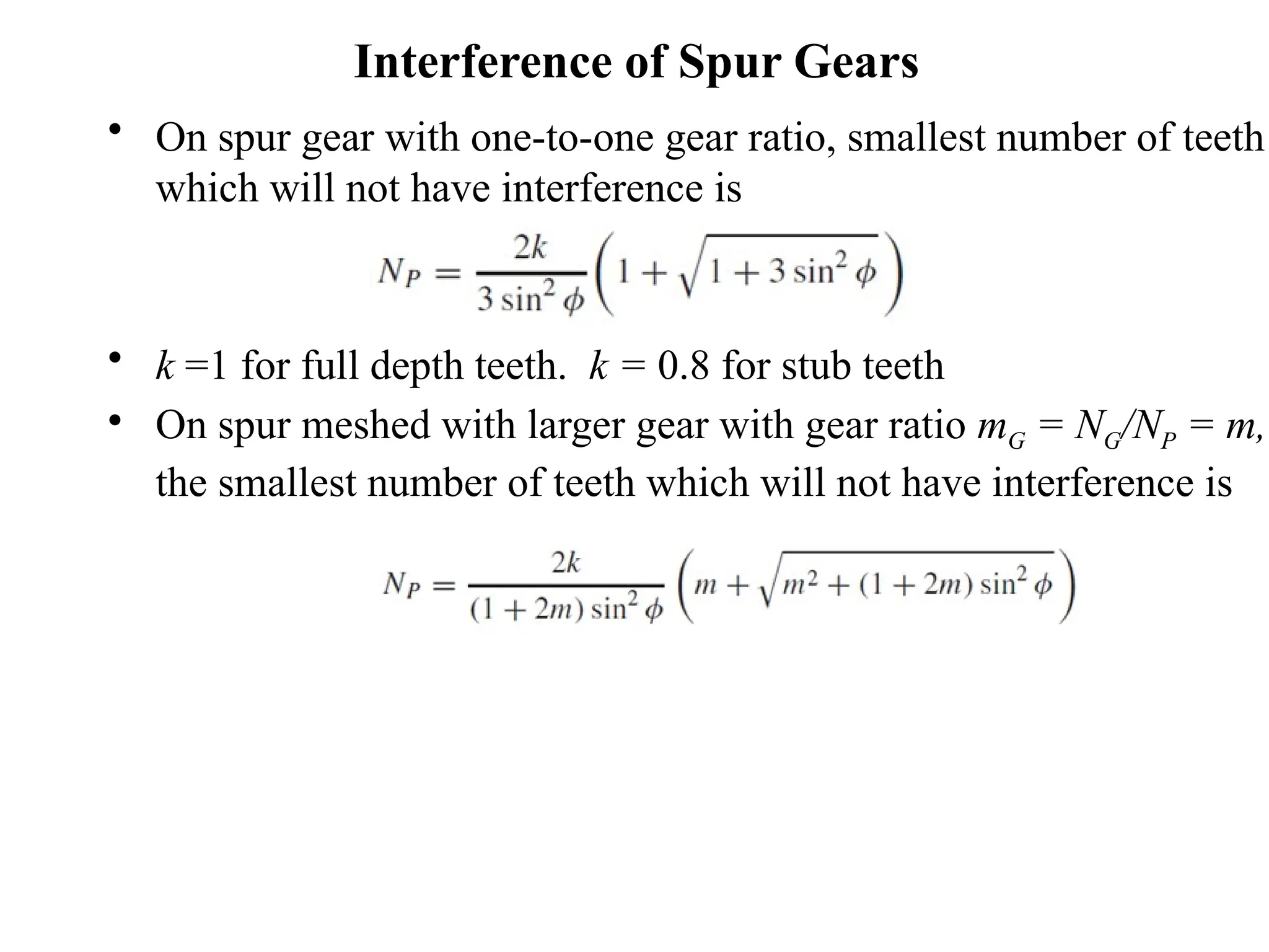
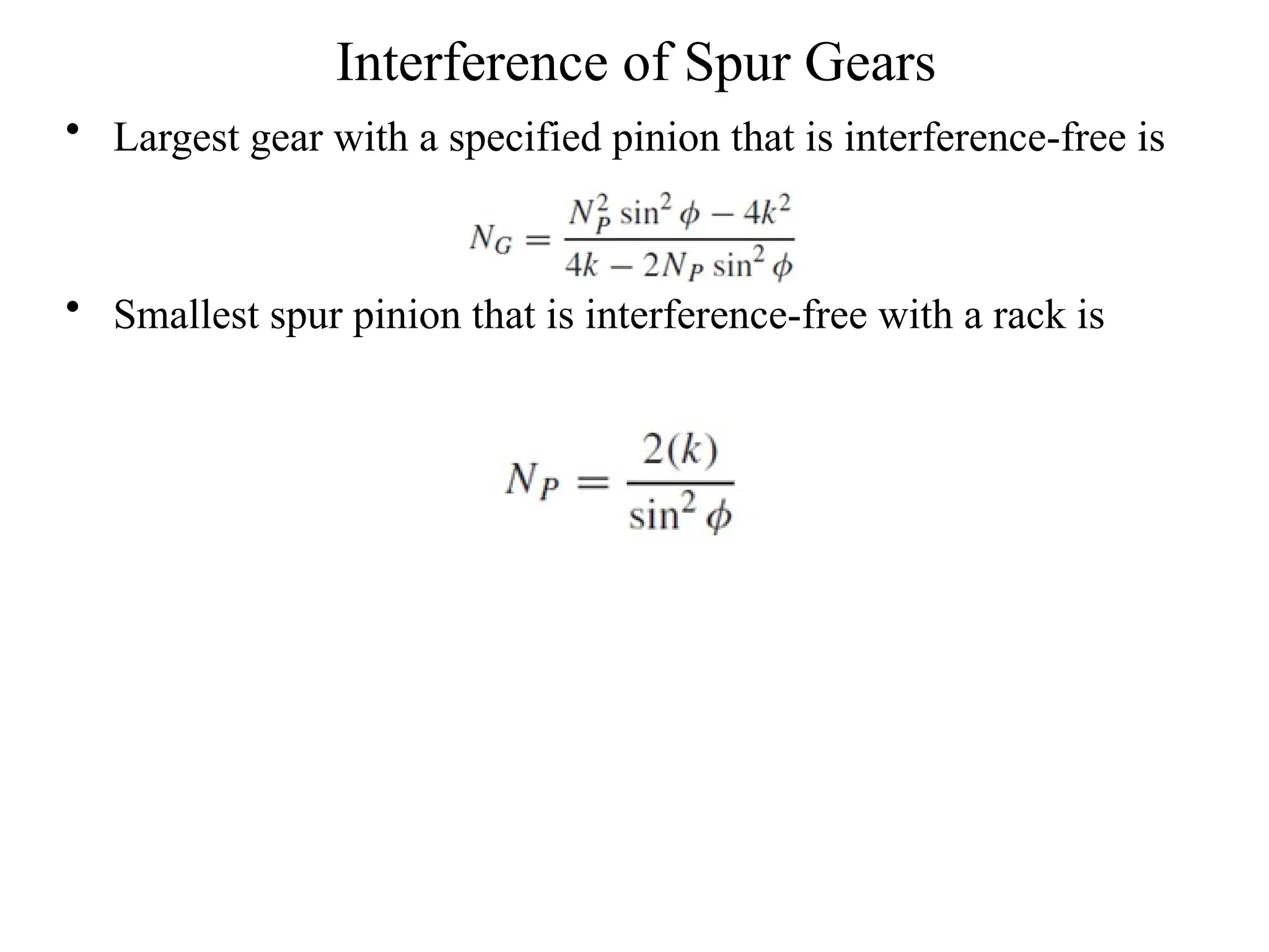
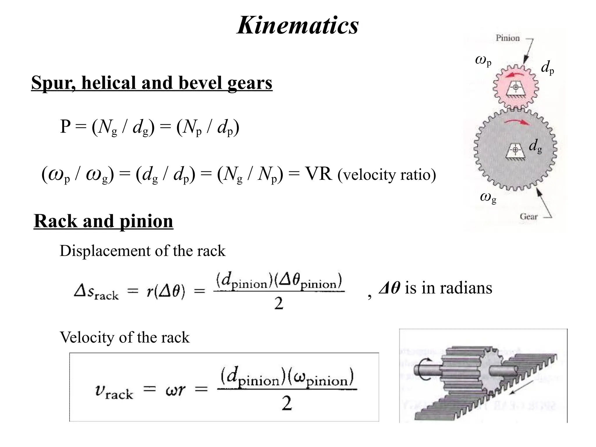
Fundamentals of Gears
♣Gears are most often used in transmissions to convert an
electric motor’s high speed and low torque to a
shaft’s requirements for low speed high torque:
♣ Speed is easy to generate, because voltage is easy to
generate
♣ Torque is difficult to generate because it requires large
amounts of current
♣ Gears essentially allow positive engagement between
teeth so high forces can be transmitted while still
undergoing essentially rolling contact
♣ Gears do not depend on friction and do best when
friction is minimized
Types of Gears
Spur gears – tooth profile is parallel to
the axis of rotation, transmits motion
between parallel shafts.
Pinion (small gear)
Gear (large gear)
Internal gears
– teeth are inclined to
the axis of rotation, the angle provides
more gradual engagement of the teeth
during meshing, transmits motion
between parallel shafts.
Helical gears
Types of Gears
Bevel gears – teeth are formed on a
conical surface, used to transfer
motion between non-parallel and
intersecting shafts.
Straight
bevel gear
Spiral
bevel gear
Types of Gears
Worm gear sets – consists of a
helical gear and a power screw (worm),
used to transfer motion between non-
parallel and non-intersecting shafts.
Rack and Pinion sets – a special
case of spur gears with the gear
having an infinitely large diameter,
the teeth are laid flat.
Rack
Pinion
Gear Design and Analysis
• Kinematics of gear teeth and gear trains.
• Force analysis.
• Design based on tooth bending strength.
• Design based on tooth surface strength.
Nomenclature
• The pitch circle is a theoretical circle upon which all calculations are usually based;
its diameter is the pitch diameter.
• A pinion is the smaller of two mating gears. The larger is often called the gear.
• The circular pitch p is the distance, measured on the pitch circle, from a point on one
tooth to a corresponding point on an adjacent tooth.
• The module m is the ratio of the pitch diameter to the number of teeth.
• The diametral pitch P is the ratio of the number of teeth on the gear to the pitch
diameter.
• The addendum a is the radial distance between the top land and the pitch circle.
• The dedendum b is the radial distance from the bottom land to the pitch circle. The
whole depth ht is the sum of the addendum and the dedendum.
• The clearance circle is a circle that is tangent to the addendum circle of the mating
gear.
• The clearance c is the amount by which the dedendum in a given gear exceeds the
addendum of its mating gear.
• The backlash is the amount by which the width of a tooth space exceeds the
thickness of the engaging tooth measured on the pitch circles.
Nomenclature of Spur Gear Teeth
= (tooth spacing)driven gear – (tooth thickness)driver , measured
on the pitch circle.
Backlash
Pitch circle
gear diam.
Fillet radius
Clearance
Base Circle
Fundamental Law and Involute Curve
Generation of the involute curve
Tangent at the
point of contact
rG
rP
rG / rP = constant (constant speed ratio) All common normals have to
intersect at the same point P
Useful Relations
P = N / d
P = diametral pitch, teeth per inch
N = number of teeth
d = pitch diameter (gear diameter)
m (module, mm) = d / N
Metric system
p (circular pitch) = πd / N
Pp = π
Diametral Pitch P = 1/m in teeth/mm
Standard Tooth Specifications
Pressure angle
Two mating gears must have the same diametral pitch, P,
and pressure angle, φ.
Pitch
line
Line of centers
Line of action
Base
circle
Base
circle
Pitch
circle
Pitch
circle
Pressure angle φ
Standard pressure angles, 14.5o
(old), 20o
, and 25o
Standard Tooth Specifications
Power
transmission,
9/P ≤ b ≤ 13/P
2 ≤ P ≤ 16
Tooth Sizes in General Use
Standardized Tooth Systems (Spur Gears)
Circles of a Gear Layout
Sequence of Gear Layout
• Pitch circles in contact
• Pressure line at desired
pressure angle
• Base circles tangent to
pressure line
• Involute profile from base
circle
• Cap teeth at addendum circle
at 1/P from pitch circle
• Root of teeth at dedendum
circle at 1.25/P from pitch
circle
• Tooth spacing from circular
pitch,
p = p / P
Relation of Base Circle to Pressure Angle
rB = rcosɸ
Tooth Action
 First point of
contact at a where
flank of pinion
touches tip of gear
 Last point of
contact at b where
tip of pinion
touches flank of
gear
 Line ab is line of
action
 Angle of action is
sum of angle of
approach and
angle of recess
Contact Ratio
• Arc of action qt is the sum of the arc of approach qa and the arc of
recess qr., that is qt = qa + qr
• The contact ratio mc is the ratio of the arc of action and the circular
pitch.
mc = qt/P
• The contact ratio is the average number of pairs of teeth in contact.
Contact Ratio
• Contact ratio can also be found from the length of the line of action
• The contact ratio should be at least 1.2
Length of contact
Standard gear:
Non-standard gear:
Interference
• Contact of portions of
tooth profiles that are not
conjugate is called
interference.
• Occurs when contact
occurs below the base
circle
• If teeth were produced by
generating process (rather
than stamping), then the
generating process
removes the interfering
portion; known as
undercutting.
Interference will occur when
or
or
Interference of Spur Gears
• On spur gear with one-to-one gear ratio, smallest number of teeth
which will not have interference is
• k =1 for full depth teeth. k = 0.8 for stub teeth
• On spur meshed with larger gear with gear ratio mG = NG/NP = m,
the smallest number of teeth which will not have interference is
Interference of Spur Gears
• Largest gear with a specified pinion that is interference-free is
• Smallest spur pinion that is interference-free with a rack is
Kinematics
(ωp / ωg) = (dg / dp) = (Ng / Np) = VR (velocity ratio)
P = (Ng / dg) = (Np / dp)
Spur, helical and bevel gears
ωg
dg
ωp
dp
Rack and pinion
Velocity of the rack
Displacement of the rack
Δθ is in radians
,
Kinematics
Worm Gear Sets
Ng = number of teeth on the helical gear
Nw = number of threads on the worm,
usually between 2 - 6
Speed ratio = Ng / Nw
Large reduction in one step, but lower
efficiency due heat generation.
Worm
Helical gear
Kinematics of Gear Trains
Conventional gear trains
ω3
ω2
=
N2
N3
ω3 ω4
=
, ω5
ω4
=
N4
N5
,
mV = e = train value
Speed ratio
ω5
ω2
=
output
input
=
Reverted gear train – output shaft is
concentric with the input shaft. Center
distances of the stages must be equal.
Kinematics of Gear Trains
Planetary gear trains
gear =arm + gear/arm
F/arm =F - arm , L/arm = L - arm
= e (train value)
Kinematics of Gear Trains
Determine the speed of the sun gear if the arm rotates at 1 rpm.
Ring gear is stationary.
2 degrees of freedom, two inputs are needed to control the system
Planetary Gear Trains - Example
For the speed reducer shown, the input
shaft a is in line with output shaft b. The
tooth numbers are N2=24, N3=18, N5=22,
and N6=64. Find the ratio of the output
speed to the input speed. Will both shafts
rotate in the same direction? Gear 6 is a
fixed internal gear.
Train value = (-N2 / N3)(N5 / N6) = (-24/18)(22/64) = - 0.4583
-.4583 = (ωL – ωarm) / (ωF – ωarm) = (0 – ωarm) / (1 – ωarm)
ωarm = 0.314,
Input and output shafts rotate in the same direction
d2 + d3 = d6 – d5

Gear Lectures_class1(1).pptxsfedvceeceeeeeeeeeeeeeee

  • 1.
  • 2.
    ♣Gears are mostoften used in transmissions to convert an electric motor’s high speed and low torque to a shaft’s requirements for low speed high torque: ♣ Speed is easy to generate, because voltage is easy to generate ♣ Torque is difficult to generate because it requires large amounts of current ♣ Gears essentially allow positive engagement between teeth so high forces can be transmitted while still undergoing essentially rolling contact ♣ Gears do not depend on friction and do best when friction is minimized
  • 3.
    Types of Gears Spurgears – tooth profile is parallel to the axis of rotation, transmits motion between parallel shafts. Pinion (small gear) Gear (large gear) Internal gears – teeth are inclined to the axis of rotation, the angle provides more gradual engagement of the teeth during meshing, transmits motion between parallel shafts. Helical gears
  • 4.
    Types of Gears Bevelgears – teeth are formed on a conical surface, used to transfer motion between non-parallel and intersecting shafts. Straight bevel gear Spiral bevel gear
  • 5.
    Types of Gears Wormgear sets – consists of a helical gear and a power screw (worm), used to transfer motion between non- parallel and non-intersecting shafts. Rack and Pinion sets – a special case of spur gears with the gear having an infinitely large diameter, the teeth are laid flat. Rack Pinion
  • 6.
    Gear Design andAnalysis • Kinematics of gear teeth and gear trains. • Force analysis. • Design based on tooth bending strength. • Design based on tooth surface strength.
  • 7.
    Nomenclature • The pitchcircle is a theoretical circle upon which all calculations are usually based; its diameter is the pitch diameter. • A pinion is the smaller of two mating gears. The larger is often called the gear. • The circular pitch p is the distance, measured on the pitch circle, from a point on one tooth to a corresponding point on an adjacent tooth. • The module m is the ratio of the pitch diameter to the number of teeth. • The diametral pitch P is the ratio of the number of teeth on the gear to the pitch diameter. • The addendum a is the radial distance between the top land and the pitch circle. • The dedendum b is the radial distance from the bottom land to the pitch circle. The whole depth ht is the sum of the addendum and the dedendum. • The clearance circle is a circle that is tangent to the addendum circle of the mating gear. • The clearance c is the amount by which the dedendum in a given gear exceeds the addendum of its mating gear. • The backlash is the amount by which the width of a tooth space exceeds the thickness of the engaging tooth measured on the pitch circles.
  • 8.
    Nomenclature of SpurGear Teeth = (tooth spacing)driven gear – (tooth thickness)driver , measured on the pitch circle. Backlash Pitch circle gear diam. Fillet radius Clearance Base Circle
  • 9.
    Fundamental Law andInvolute Curve Generation of the involute curve Tangent at the point of contact rG rP rG / rP = constant (constant speed ratio) All common normals have to intersect at the same point P
  • 10.
    Useful Relations P =N / d P = diametral pitch, teeth per inch N = number of teeth d = pitch diameter (gear diameter) m (module, mm) = d / N Metric system p (circular pitch) = πd / N Pp = π Diametral Pitch P = 1/m in teeth/mm
  • 11.
    Standard Tooth Specifications Pressureangle Two mating gears must have the same diametral pitch, P, and pressure angle, φ. Pitch line Line of centers Line of action Base circle Base circle Pitch circle Pitch circle Pressure angle φ Standard pressure angles, 14.5o (old), 20o , and 25o
  • 12.
  • 13.
    Tooth Sizes inGeneral Use
  • 14.
  • 15.
    Circles of aGear Layout
  • 16.
    Sequence of GearLayout • Pitch circles in contact • Pressure line at desired pressure angle • Base circles tangent to pressure line • Involute profile from base circle • Cap teeth at addendum circle at 1/P from pitch circle • Root of teeth at dedendum circle at 1.25/P from pitch circle • Tooth spacing from circular pitch, p = p / P
  • 17.
    Relation of BaseCircle to Pressure Angle rB = rcosɸ
  • 20.
    Tooth Action  Firstpoint of contact at a where flank of pinion touches tip of gear  Last point of contact at b where tip of pinion touches flank of gear  Line ab is line of action  Angle of action is sum of angle of approach and angle of recess
  • 21.
    Contact Ratio • Arcof action qt is the sum of the arc of approach qa and the arc of recess qr., that is qt = qa + qr • The contact ratio mc is the ratio of the arc of action and the circular pitch. mc = qt/P • The contact ratio is the average number of pairs of teeth in contact.
  • 22.
    Contact Ratio • Contactratio can also be found from the length of the line of action • The contact ratio should be at least 1.2
  • 23.
    Length of contact Standardgear: Non-standard gear:
  • 24.
    Interference • Contact ofportions of tooth profiles that are not conjugate is called interference. • Occurs when contact occurs below the base circle • If teeth were produced by generating process (rather than stamping), then the generating process removes the interfering portion; known as undercutting.
  • 25.
  • 26.
    Interference of SpurGears • On spur gear with one-to-one gear ratio, smallest number of teeth which will not have interference is • k =1 for full depth teeth. k = 0.8 for stub teeth • On spur meshed with larger gear with gear ratio mG = NG/NP = m, the smallest number of teeth which will not have interference is
  • 27.
    Interference of SpurGears • Largest gear with a specified pinion that is interference-free is • Smallest spur pinion that is interference-free with a rack is
  • 28.
    Kinematics (ωp / ωg)= (dg / dp) = (Ng / Np) = VR (velocity ratio) P = (Ng / dg) = (Np / dp) Spur, helical and bevel gears ωg dg ωp dp Rack and pinion Velocity of the rack Displacement of the rack Δθ is in radians ,
  • 29.
    Kinematics Worm Gear Sets Ng= number of teeth on the helical gear Nw = number of threads on the worm, usually between 2 - 6 Speed ratio = Ng / Nw Large reduction in one step, but lower efficiency due heat generation. Worm Helical gear
  • 30.
    Kinematics of GearTrains Conventional gear trains ω3 ω2 = N2 N3 ω3 ω4 = , ω5 ω4 = N4 N5 , mV = e = train value Speed ratio ω5 ω2 = output input = Reverted gear train – output shaft is concentric with the input shaft. Center distances of the stages must be equal.
  • 32.
    Kinematics of GearTrains Planetary gear trains gear =arm + gear/arm F/arm =F - arm , L/arm = L - arm = e (train value)
  • 33.
    Kinematics of GearTrains Determine the speed of the sun gear if the arm rotates at 1 rpm. Ring gear is stationary. 2 degrees of freedom, two inputs are needed to control the system
  • 34.
    Planetary Gear Trains- Example For the speed reducer shown, the input shaft a is in line with output shaft b. The tooth numbers are N2=24, N3=18, N5=22, and N6=64. Find the ratio of the output speed to the input speed. Will both shafts rotate in the same direction? Gear 6 is a fixed internal gear. Train value = (-N2 / N3)(N5 / N6) = (-24/18)(22/64) = - 0.4583 -.4583 = (ωL – ωarm) / (ωF – ωarm) = (0 – ωarm) / (1 – ωarm) ωarm = 0.314, Input and output shafts rotate in the same direction d2 + d3 = d6 – d5