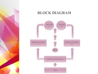
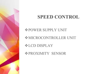
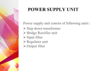
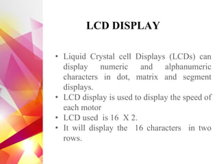
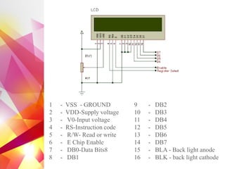
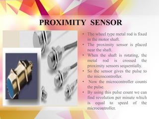
The document details the design and development of a cost-effective cricket bowling machine that accommodates various ball types and bowling styles. It includes specifications for components such as induction motors, wheels, and a microcontroller, along with features like speed control and an LCD display for monitoring. Future improvements aim to incorporate advanced bowling technologies and safety measures.

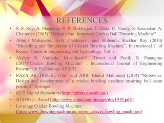
![COMPONENTS USED
• Induction Motors
[2500rpm, 0.35HP,
0.5amp]
• Trolley Wheels
[diameter=21cm]
• Electronic Regulators
• Ball Bearing
• Antifriction Bearing
• Sleeve Bearing
• Flange Bolts
• Screws
• Metal Frame
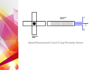
• Proximity Sensor
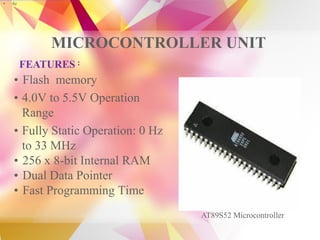
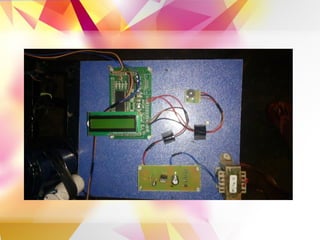
• AT89S52
Microcontroller
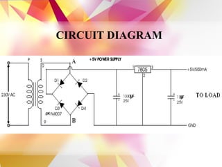
• IC 7805
• LED
• LCD 16×2](https://image.slidesharecdn.com/apr2k16finalreviewppt-170906144934/85/Presentation-on-Cricket-Bowling-Machine-4-320.jpg)


![Electronic fuel injection system [EFI]](https://cdn.slidesharecdn.com/ss_thumbnails/efibilkulfinal-171227111232-thumbnail.jpg?width=640&height=640&fit=bounds)


![Engine management system[ EMS ] or Engine Control Unit [ ECU ]](https://cdn.slidesharecdn.com/ss_thumbnails/enginemanagementsystem-170920182131-thumbnail.jpg?width=640&height=640&fit=bounds)