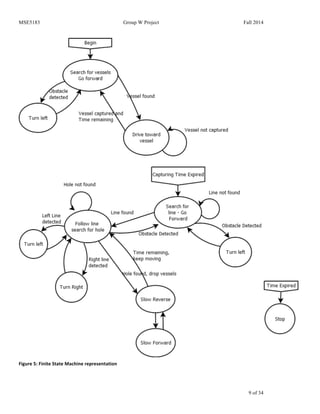
This document describes the design and implementation of a mobile robot built with Lego bricks. It discusses the mechanical design including gears, frame, sensor placement, and weight distribution. It then covers the software architecture and various algorithms used for motion control, collision avoidance, mapping, path planning, vision, localization, and object manipulation. Key techniques include implementing a unicycle dynamic model for motion, using IR sensors and sonar for collision avoidance, representing the environment as a graph for path finding, and detecting objects and landmarks through color filtering and edge detection. The robot is able to autonomously navigate environments, identify rooms, locate objects, and return them to a base location.
Hello Everyone!
This is the best ppt on Robotics. It includes all the topics from history to today's latest technology. Those who are keen to know about artificial intelligence then this ppt is the best platform to start. I am sure that you will get to know how the robots are made, their operation in industries and how they can become a part of our future technology.
Do watch and learn the whole ppt and start learning more about it for your future career.
Remember the future is here!
Thank You!
The document is a seminar report on the Celluon Evo Mouse presented by Ratna Tejaswini Gade. It provides an overview of the history of computer mice from early mechanical mice to modern optical and laser mice. It then describes the key technologies used in the Celluon Evo Mouse, including 3D electronic perception technology and image processing software. The Evo Mouse works by using infrared sensors to track finger movements on surfaces and translates these into mouse functions without the need for a physical mouse.
Motion capture involves recording human movement digitally to create realistic animations. It began in the 1970s and has since spread. There are three main types: mechanical which tracks joint angles, magnetic which uses transmitters and receivers, and optical which uses cameras and reflective markers. Optical motion capture is most common due to its freedom of movement and high quality capture. Motion capture is used extensively in movies, video games, military, medicine, and more to create realistic animations and analyze movement.
The evoMouse allows users to use their finger as a pointer instead of a physical mouse across nearly any flat surface. It requires little space. The evoMouse is made up of two principal components: 3D electronic perception sensor chips and image processing software. It connects to computers through both Bluetooth and a USB port.
The document discusses two input devices: the Evo Mouse, which turns any flat surface into a touchpad using infrared sensors and image processing, and the Magic Cube projection keyboard, which projects a virtual keyboard that can be typed on using infrared detection of finger movements. Both devices connect via USB and work on various operating systems. They provide portable, space-saving alternatives to traditional mice and keyboards.
The computer mouse was named after its resemblance to a real mouse, with the cord acting as a tail and the held part as the body. Douglas Engelbart invented the first computer mouse in 1968, which was a small wooden block with wheels and a long cable. Early mice tracked movement using external wheels or a rolling ball inside, while modern optical and laser mice use light sensors to detect movement relative to surfaces. Other mouse types include inertial mice that track movement without a surface using accelerometers, and 3D mice that provide multiple degrees of freedom through ultrasound.
Design and Development of a Semi-Autonomous Telerobotic Warehouse Management ...IRJET Journal
This document describes the design and development of a semi-autonomous telerobotic warehouse management robot for logistic applications. Key features of the robot include using an Arduino Mega microcontroller, navigating shelves independently, using LED indicators to display status, rerouting autonomously, and using audio commands to alert obstacles while maintaining compact dimensions of 300mm x 300mm x 500mm. Sensors like ultrasonic sensors, infrared sensors, and a color sensor are used for obstacle detection, line following, and shelf recognition. The robot is programmed using Arduino to follow rules for different scenarios based on sensor input, like moving forward when following a line or triggering shelf scanning when a marking is detected.
This document provides a summary of the system design for an autonomous robot. It describes the hardware components available including Lego Mindstorms kits with sensors, motors and structural parts. It also describes the available software tools and programming languages. The document outlines the system model, software and hardware capabilities and compatibility. It details the reusable components from previous projects and the planned software and mechanical structures. It explains the coordinate system, localization, navigation and other methodologies to be used.
This document describes the ARCduino, an RC car that can detect collisions and avoid them autonomously using an ultrasonic sensor. The car averages 3 distance readings from the sensor to correct for inaccurate readings. It was designed to be a simple but fun childhood toy that could also serve as a prototype for safety features in future automated vehicles. The document outlines the project objectives of stopping before collisions and backing up, provides diagrams of the design and software flow, and includes manuals for users and programmers as well as references for additional resources.
This document summarizes a college project to build an Arduino-based robot that can track and follow an infrared LED. The robot uses an array of 8 infrared sensors connected to an Arduino Uno microcontroller. The Arduino processes the sensor data and controls two continuous rotation servomotors that drive the wheels. Testing showed the robot could track the infrared LED from up to 14 meters away. Issues with sensor field of view and reflective surfaces hindered tracking at close ranges. Adding distance sensors was proposed to help with navigation if the infrared signal is lost. The overall goal of building a robot capable of infrared tracking and following was accomplished.
Development of wearable object detection system & blind stick for visuall...Arkadev Kundu
It is a wearable device. It has a camera, and it detects all living and non living object. This module detects moving object also. It is made with raspberry pi 3, and a camera. One headphone connect with raspberry pi. When this module detects items, it gave a sound output through headphone. Hence the blind man know that item, which is in-front of him or her. We made it in very low budget, and it is very helpful for visually challenged people. And the Blind stick help him to detect obstacles.
The document describes a quadcopter drone designed by Temple University students to autonomously solve mazes. It uses an Android phone for computer vision and maze solving algorithms. An Arduino board interfaces with ultrasonic sensors to detect obstacles and an IMU for orientation data. The design addresses needs like maze input/solving, obstacle avoidance, and landing zone detection to complete the task of navigating a predefined disaster scenario maze autonomously.
Intelligent Embedded Systems (Robotics)Adeyemi Fowe
This document summarizes a student project that aims to design an autonomous exploration robot capable of path navigation and object search. The proposed design uses embedded systems programming to enable the robot to anonymously search for objects using machine learning, computer vision, path navigation and obstacle avoidance technologies. A demonstration was implemented using an iRobot Create platform, Gumstix computers, sensors and a wireless IP camera to detect and locate a red object in a lab environment. The project has potential applications in geology, space exploration, surveillance and more.
1) The document describes a method for obstacle detection using a laser and single camera. A BeagleBoard is used as an image processing platform to obtain 3D images from 2D images captured by the camera.
2) A laser is mounted on a servo motor controlled by an Arduino board. The laser scans the object while the camera captures images. OpenCV software processes the images to detect the object based on laser tracking.
3) The system is designed to identify objects in its environment and obtain a 3D perspective view by constantly capturing images using a webcam as the laser scans, processed using an algorithm.
IRJET- Review on Colored Object Sorting System using Arduino UNOIRJET Journal
This document describes a system for sorting colored objects using an Arduino Uno microcontroller. The system uses a color sensor to detect the color of objects passing on a conveyor belt. If the object's color matches the desired color, the Arduino allows it to pass to the end of the belt. If not, the Arduino activates a linear actuator to push the object off the belt. The system is designed to automate object sorting, reducing manual labor while increasing sorting accuracy and speed compared to human sorting. It has applications in food processing, toy manufacturing, and other industries.
This document provides an overview of the VIP Secure Hardware Wheelchair Team's progress in the spring 2016 semester. It discusses the hardware and software architecture of the robotic wheelchair system, including improvements made to the odometry system and motor control. The team separated into subgroups to work on odometry, motor control, and hardware architecture. Goals for the semester included reworking the motor control code, implementing a ROS software architecture, and debugging the odometry code. Significant progress was made on these goals.
Applications Of Mems In Robotics And Bio Mems Using Psoc With Metal Detector ...IOSR Journals
Abstract: This project deals with accelerometercontrolled robot with wireless image and voice transmission as well as metal Detector. This robot is prototype for the “Path Finder”. This robot is controlled based on PSoCdevice using MEMS accelerometer remote. This can be moved forward and reverse direction using geared motors of 60RPM. Also this robot can take sharp turnings towards left and right directions. A high sensitive induction type metal detector is designed using colpitts oscillator principle and fixed to this robot. Also a wireless camera with voice is interfaced to the kit. When the robot is moving on a surface, the system produces a beep sound when metal is detected. This beep sound will be transmitted to remote place. Simultaneously the images around the robot will be transmitted to remote place. User can monitor the images and metal detection alarms on Television. Keywords: PSoC designer 1.0, keil -c,PSOC device (CY8C29466), AT89S52.
The document describes the progress of a student project to build a line following robot that can measure mobile and Wi-Fi signal strengths. Over 15 days, the students researched components, wrote code, tested ideas, and problem-solved issues. They designed the robot to use infrared sensors to follow a line, Arduino shields to measure signals, and an ultrasonic sensor and recorded turns to locate the strongest signal area.
The document describes an All-Terrain Autonomous Vehicle (ATAV) designed and built for a class project. The ATAV uses a tank-style continuous track chassis powered by two motors controlled by an Arduino microcontroller. An ultrasonic sensor mounted on a servo detects obstacles and allows the ATAV to navigate around them to reach a target location. The ATAV was designed in phases, testing the drivetrain, integrating sensors, and adding localization functions to enable autonomous navigation between start and end points while avoiding obstacles. Testing showed the ATAV could successfully detect and maneuver around obstacles to reach its target location.
This document is the final report for an autonomous roving vehicle (ARV) designed by Team DC1 to collect phenotype data from soybean plants. It summarizes the design evolution and selection of a rocker bogie frame with four tracks. Mathematical models were constructed to analyze ground pressure, vehicle tilt under terrain variations, and power consumption. The final design and bill of materials are presented, with a total estimated cost of $15,800. Future work is still needed on plant shields, finalizing track and generator dimensions, track mounts, sensor integration, and fabrication before prototyping. The ARV is intended to autonomously traverse soybean fields to rapidly collect accurate plant data for researchers analyzing genetic traits.
Jim Williamson's technical portfolio includes consumer and industrial optical product work. For consumer products, he invented an award-winning vertical scanner, non-imaging illuminator, waveguide scanhead, phone sensors, optical storage film, and a laser toy. For industrial products, he designed III-V detectors for instruments, an array detector and spectrometer, and a flat response detector for power meters. His experience spans optics, optoelectronics, testing, materials processing, research, design, development, applications, electronics, mechanical design, and programming.
The document describes an autonomous hazmat cleanup robot project created by engineering students. The robot uses sensors like an infrared sensor, color sensor, and electromagnet to identify and pick up hazardous materials and parts. It was designed to operate autonomously in an industrial building by communicating with another robot to transfer collected objects. The robot is powered by batteries and controlled with an Arduino microcontroller. Tests were performed on the sensors and electromagnet to ensure proper functionality.
This document outlines the design of an autonomous robot created for an EGRE 364 course final project. It describes the mechanical, electrical, and software design of the robot, which was meant to navigate a maze, follow a black line, and draw a picture. The mechanical design consisted of a plastic base with breadboards for structure and mounting motors, wheels, and sensors. The electrical design used an H-bridge chip and microcontroller to control motors and read sensors. The placement of components like motors, wheels, and sensors is explained in detail with diagrams.
The document summarizes a project report for an autonomous robot named NA-YATR submitted to The Robotics Club. The report describes the components used including Arduino, motors, sensors, and software. It explains the working of the robot using A* pathfinding and ultrasonic sensors for obstacle avoidance. Experimental results showed the robot could efficiently detect obstacles and change paths to reach its destination. Future enhancements are discussed to improve functionality.
The document describes the design, construction, and programming of an octocopter drone intended to scan and model buildings in 3D. An octocopter frame was built using metal and 3D printed parts with eight motors, batteries, and an autopilot system. Software was programmed to take photos from the drone's camera during flight and stitch them together into a 3D model. Testing progressed from tethered indoor flights to autonomous outdoor flights following programmed paths. The final successful result was a functioning octocopter capable of automated building scans and 3D modeling.
Real-Time Map Building using Ultrasound ScanningIRJET Journal
This document describes a device that uses an ultrasonic sensor to build maps of environments in real-time. The device scans the sensor across a 180 degree range to collect distance data points and generates a 2D map visualization. It is intended to enable robots to autonomously map and navigate environments. The device was able to generate basic maps of test environments but had some inaccuracies, depicting flat surfaces as arcs rather than straight lines due to the wide beam of the ultrasonic sensor. Improving the sensor resolution could help address these inaccuracies. The real-time mapping ability, low cost, and small size make the device suitable for mobile robot applications.
Electric vehicle and photovoltaic advanced roles in enhancing the financial p...IJECEIAES
Climate change's impact on the planet forced the United Nations and governments to promote green energies and electric transportation. The deployments of photovoltaic (PV) and electric vehicle (EV) systems gained stronger momentum due to their numerous advantages over fossil fuel types. The advantages go beyond sustainability to reach financial support and stability. The work in this paper introduces the hybrid system between PV and EV to support industrial and commercial plants. This paper covers the theoretical framework of the proposed hybrid system including the required equation to complete the cost analysis when PV and EV are present. In addition, the proposed design diagram which sets the priorities and requirements of the system is presented. The proposed approach allows setup to advance their power stability, especially during power outages. The presented information supports researchers and plant owners to complete the necessary analysis while promoting the deployment of clean energy. The result of a case study that represents a dairy milk farmer supports the theoretical works and highlights its advanced benefits to existing plants. The short return on investment of the proposed approach supports the paper's novelty approach for the sustainable electrical system. In addition, the proposed system allows for an isolated power setup without the need for a transmission line which enhances the safety of the electrical network
Presentation of IEEE Slovenia CIS (Computational Intelligence Society) Chapte...University of Maribor
Slides from talk presenting:
Aleš Zamuda: Presentation of IEEE Slovenia CIS (Computational Intelligence Society) Chapter and Networking.
Presentation at IcETRAN 2024 session:
"Inter-Society Networking Panel GRSS/MTT-S/CIS
Panel Session: Promoting Connection and Cooperation"
IEEE Slovenia GRSS
IEEE Serbia and Montenegro MTT-S
IEEE Slovenia CIS
11TH INTERNATIONAL CONFERENCE ON ELECTRICAL, ELECTRONIC AND COMPUTING ENGINEERING
3-6 June 2024, Niš, Serbia
Optimizing Gradle Builds - Gradle DPE Tour Berlin 2024Sinan KOZAK
Sinan from the Delivery Hero mobile infrastructure engineering team shares a deep dive into performance acceleration with Gradle build cache optimizations. Sinan shares their journey into solving complex build-cache problems that affect Gradle builds. By understanding the challenges and solutions found in our journey, we aim to demonstrate the possibilities for faster builds. The case study reveals how overlapping outputs and cache misconfigurations led to significant increases in build times, especially as the project scaled up with numerous modules using Paparazzi tests. The journey from diagnosing to defeating cache issues offers invaluable lessons on maintaining cache integrity without sacrificing functionality.
Harnessing WebAssembly for Real-time Stateless Streaming PipelinesChristina Lin
Traditionally, dealing with real-time data pipelines has involved significant overhead, even for straightforward tasks like data transformation or masking. However, in this talk, we’ll venture into the dynamic realm of WebAssembly (WASM) and discover how it can revolutionize the creation of stateless streaming pipelines within a Kafka (Redpanda) broker. These pipelines are adept at managing low-latency, high-data-volume scenarios.
Embedded machine learning-based road conditions and driving behavior monitoringIJECEIAES
Car accident rates have increased in recent years, resulting in losses in human lives, properties, and other financial costs. An embedded machine learning-based system is developed to address this critical issue. The system can monitor road conditions, detect driving patterns, and identify aggressive driving behaviors. The system is based on neural networks trained on a comprehensive dataset of driving events, driving styles, and road conditions. The system effectively detects potential risks and helps mitigate the frequency and impact of accidents. The primary goal is to ensure the safety of drivers and vehicles. Collecting data involved gathering information on three key road events: normal street and normal drive, speed bumps, circular yellow speed bumps, and three aggressive driving actions: sudden start, sudden stop, and sudden entry. The gathered data is processed and analyzed using a machine learning system designed for limited power and memory devices. The developed system resulted in 91.9% accuracy, 93.6% precision, and 92% recall. The achieved inference time on an Arduino Nano 33 BLE Sense with a 32-bit CPU running at 64 MHz is 34 ms and requires 2.6 kB peak RAM and 139.9 kB program flash memory, making it suitable for resource-constrained embedded systems.
TIME DIVISION MULTIPLEXING TECHNIQUE FOR COMMUNICATION SYSTEMHODECEDSIET
Time Division Multiplexing (TDM) is a method of transmitting multiple signals over a single communication channel by dividing the signal into many segments, each having a very short duration of time. These time slots are then allocated to different data streams, allowing multiple signals to share the same transmission medium efficiently. TDM is widely used in telecommunications and data communication systems.
### How TDM Works
1. **Time Slots Allocation**: The core principle of TDM is to assign distinct time slots to each signal. During each time slot, the respective signal is transmitted, and then the process repeats cyclically. For example, if there are four signals to be transmitted, the TDM cycle will divide time into four slots, each assigned to one signal.
2. **Synchronization**: Synchronization is crucial in TDM systems to ensure that the signals are correctly aligned with their respective time slots. Both the transmitter and receiver must be synchronized to avoid any overlap or loss of data. This synchronization is typically maintained by a clock signal that ensures time slots are accurately aligned.
3. **Frame Structure**: TDM data is organized into frames, where each frame consists of a set of time slots. Each frame is repeated at regular intervals, ensuring continuous transmission of data streams. The frame structure helps in managing the data streams and maintaining the synchronization between the transmitter and receiver.
4. **Multiplexer and Demultiplexer**: At the transmitting end, a multiplexer combines multiple input signals into a single composite signal by assigning each signal to a specific time slot. At the receiving end, a demultiplexer separates the composite signal back into individual signals based on their respective time slots.
### Types of TDM
1. **Synchronous TDM**: In synchronous TDM, time slots are pre-assigned to each signal, regardless of whether the signal has data to transmit or not. This can lead to inefficiencies if some time slots remain empty due to the absence of data.
2. **Asynchronous TDM (or Statistical TDM)**: Asynchronous TDM addresses the inefficiencies of synchronous TDM by allocating time slots dynamically based on the presence of data. Time slots are assigned only when there is data to transmit, which optimizes the use of the communication channel.
### Applications of TDM
- **Telecommunications**: TDM is extensively used in telecommunication systems, such as in T1 and E1 lines, where multiple telephone calls are transmitted over a single line by assigning each call to a specific time slot.
- **Digital Audio and Video Broadcasting**: TDM is used in broadcasting systems to transmit multiple audio or video streams over a single channel, ensuring efficient use of bandwidth.
- **Computer Networks**: TDM is used in network protocols and systems to manage the transmission of data from multiple sources over a single network medium.
### Advantages of TDM
- **Efficient Use of Bandwidth**: TDM all
Comparative analysis between traditional aquaponics and reconstructed aquapon...bijceesjournal
The aquaponic system of planting is a method that does not require soil usage. It is a method that only needs water, fish, lava rocks (a substitute for soil), and plants. Aquaponic systems are sustainable and environmentally friendly. Its use not only helps to plant in small spaces but also helps reduce artificial chemical use and minimizes excess water use, as aquaponics consumes 90% less water than soil-based gardening. The study applied a descriptive and experimental design to assess and compare conventional and reconstructed aquaponic methods for reproducing tomatoes. The researchers created an observation checklist to determine the significant factors of the study. The study aims to determine the significant difference between traditional aquaponics and reconstructed aquaponics systems propagating tomatoes in terms of height, weight, girth, and number of fruits. The reconstructed aquaponics system’s higher growth yield results in a much more nourished crop than the traditional aquaponics system. It is superior in its number of fruits, height, weight, and girth measurement. Moreover, the reconstructed aquaponics system is proven to eliminate all the hindrances present in the traditional aquaponics system, which are overcrowding of fish, algae growth, pest problems, contaminated water, and dead fish.
Introduction- e - waste – definition - sources of e-waste– hazardous substances in e-waste - effects of e-waste on environment and human health- need for e-waste management– e-waste handling rules - waste minimization techniques for managing e-waste – recycling of e-waste - disposal treatment methods of e- waste – mechanism of extraction of precious metal from leaching solution-global Scenario of E-waste – E-waste in India- case studies.
ACEP Magazine edition 4th launched on 05.06.2024Rahul
This document provides information about the third edition of the magazine "Sthapatya" published by the Association of Civil Engineers (Practicing) Aurangabad. It includes messages from current and past presidents of ACEP, memories and photos from past ACEP events, information on life time achievement awards given by ACEP, and a technical article on concrete maintenance, repairs and strengthening. The document highlights activities of ACEP and provides a technical educational article for members.
ISPM 15 Heat Treated Wood Stamps and why your shipping must have one
Autonomous Robot
1. Lawrence Technological University
MSE5183 – Mechatronics I
Fall 2014
Project: Collect Waste Containers and Transport to Storage Facility
Group W
David Bowden
Salim Al Oufi
Vijay Krishna Nandan Srikakolapu
Graduate Students:
"I pledge that on all academic work that I submit, I will neither give nor receive unauthorized aid, nor will I
present another person's work as my own."
2. MSE5183 Group W Project Fall 2014
2 of 34
ABSTRACT
We designed and built a small robot with the purpose of identifying and retrieving a number of small round
storage containers (tennis balls), and delivering them to a long term storage facility (by dropping them through a
hole in the ground). To achieve this goal, we built a chassis capable of fitting within the storage shed (a 12”
cube), selected sensors to identify the storage containers, the walls around the facility, and the path to the long
term storage facility, and wrote code to navigate the robot through the process of picking up containers and
conveying them to the storage facility, with the goal of moving up to three containers in less that one minute.
INTRODUCTION
The project involves the creation of an autonomous robot to operate inside a 7’x7’ surface, bounded by red lines and 7”
high walls, identify waste storage containers (tennis balls), collect them, and move them to a long term storage facility (a
hole in the surface of the board). The surface of the board is white, and there is a large black circular path around the
center, leading to the storage facility borehole. During the demonstration, the position of the robot and up to three
containment vessels will be randomly determined.
Figure
1:
Operational
surface
layout
We chose to use an Arduino Uno R3 processor as controller for the project, as it was the only platform that all members of
the project group were familiar with.
3. MSE5183 Group W Project Fall 2014
3 of 34
ROBOT DESIGN
1. Drivetrain and Chassis
We originally hoped to find a moderately priced (under $100) chassis including motors and wheels to
stand as a base from which to build the remainder of the project. We tested a number of motors of the
types that are included with inexpensive chassis kits, and were not impressed with their capabilities. The
few kits that did look to meet our needs far exceeded our price range. We determined that we’d likely be
better off getting some higher quality motors and controllers, and building our own chassis around them.
One of the group members had some motor/transmission/wheel combination modules in his basement,
leftover from a previous project. He had originally considered them too large (6” wheels) for this project,
but the group decided that the large diameter of the wheels could be considered a positive attribute, as they
might allow the robot to ignore the hole in the board which might serve as a trap for smaller diameter
wheels. The group concluded that they’d be a preferred alternative to ordering new motors and waiting for
shipping. As an additional bonus, since the tall wheels have the motor/transmission connected at the top,
they allow space in the bottom of the robot to collect the storage containers without having to pick them up
off the surface.
Unfortunately the wheel/transmission/motor assemblies were just slightly too wide (6.5”) to position them
side by side within a 12” width. We explored various positions of the wheel assemblies, and eventually
concluded that setting the wheels on alternate diagonal corners of the available space would provide the
best performance for the least complexity. The group opted to use sliders at the opposite corners to
prevent the structure tipping over and provide greater stability to the supporting portions of the robot
(Arduino, motor controllers, batteries, and sensors), yet allow for movement in any direction.
The easiest method to attach sliders to the base is with a long support column, which can be bolted to the
base, nearly 7” up from the field surface. Rather than build a truss, or attach blocks to hold casters, we
decided to use ladles, and bend the handles to bolt to the base. Ladles are already shaped properly for the
least contact area with the surface, are (relatively) low friction stainless steel, are strong enough to support
the weight of the robot, and yet light enough to avoid overloading the frame, and are less expensive than
casters, furniture sliders, or other options that we considered. They also match with the unofficial theme
of the group (Group W, from the Arlo Guthrie song “Alice’s Restaurant”).
The group also had access to a number of Victor 883 Motor controllers, which have several advantages
over the LM293 controllers we studied in class:
1) They are capable of controlling up to 24v at up to 60A of current.
2) They require only a single PWM input from the Arduino to control both speed and direction for each
motor.
3) We didn’t have to wait for shipping, but had them immediately available.
4. MSE5183 Group W Project Fall 2014
4 of 34
Figure
2:
Front
view
of
robot
showing
camera,
IR
sensors,
and
space
for
ball
collection
under
electronics.
We also identified two disadvantages:
1) They are more expensive than other motor controllers (mostly due to the enhanced current carrying
capability).
2) They’re a little more complicated to control, since the speed and direction are both encoded into one
signal (the same as a servo motor).
We felt that the advantages outweighed the disadvantages, and decided to use these controllers rather than
search for others with high enough current capability for the overly large motors we chose for the
drivetrain.
5. MSE5183 Group W Project Fall 2014
5 of 34
2. Gathering information for navigation (sensors)
As the location of the storage containers was not originally described, we looked into the possibility of
using a vision system to locate the containers. We were intrigued by the latest generation of the cmucam,
the Pixy, and were impressed by the demonstration video, so we purchased one.
The Pixy camera board consists of a video camera connected to a 200MHz dual-core ARM processor,
running custom firmware to detect objects and report their locations through serial communications or an
analog output. The fact that all of the image processing is done by the Pixy and only the location and size
of the objects detected is reported to the Arduino processor was important to the decision to purchase one.
We originally planned to use an ultrasound sensor to detect the distance to the balls, as the vision sensor
doesn’t directly report a distance value. However, we soon discovered that due to their shape and
composition, tennis balls are completely invisible to ultrasound sensors, so we decided to use a distance
sensing infrared sensor instead.
We also planned to use infrared sensors to detect the black line on the white surface so that we could
follow the path to the hole. The original plan was to have two path following sensors, placed close enough
together that the hole would be reported by both sensors sensing a lack of reflection.
a. Vision Sensor (Pixy) Details
The Pixy sensor provides information about objects detected by the camera with the following
information, which is sent to the Arduino with SPI (Serial Peripheral Interface) protocol:
Signature – The color signature of the detected object (up to 7 signatures can be set, so up to 7 different
types of objects can be tracked).
X – The location on the X axis of the center of the object.
Y – The location on the Y axis of the center of the object.
Width – the measurement (in pixels) of the width of the object.
Height –measurement in pixels of the height of the object.
Angle – for color codes, the angle at which the codes are aligned (not valid for normal objects).
6. MSE5183 Group W Project Fall 2014
6 of 34
Figure
3:
Object
detection
overlaid
on
camera
picture.
Our
camera
is
mounted
upside
down,
but
this
picture
has
been
rotated
to
make
identification
easier.
The
captions
on
the
boxes
read
“S
=
1”
indicating
those
boxes
are
identified
as
signature
#1.
The
two
red
pixels
on
the
ball
in
the
background
indicate
that
it
is
starting
to
be
recognized,
but
has
not
yet
met
the
minimum
number
of
pixels
for
designation
as
an
object.
For this project, we’ll make use of the Signature, X, Y, Width, and Height components of the report. The
Y (left/right) location will be the only one used for navigation. As a backup, we will also be able to verify
the object with the IR sensor, so if the object appears to be large, but is not sensed by the IR sensor, it can
safely be ignored as false. (This verification did not turn out to be necessary, so was not included in the
final project).
Technically, the camera could also be used to detect the red lines surrounding the playing field, especially
as they have a nice bright primary color, but testing has shown that the width of the line is too small for the
camera to reliably detect as an object, unless it is very close and pointing very nearly at the line.
Some of the code for the Pixy demo which chases a ball is available online at:
http://www.cmucam.org/boards/9/topics/2898?r=3372#message-3372 This is a good starting point for
using Pixy to drive the robot toward an object (it’s incomplete as posted, because a lot of the code relies
upon the physical characteristics of the robots drive system, and is only a starting point because as posted
the code always tries to keep the robot at a set distance from the object, not driving over the object as we’ll
require).
In Figure 3, our robot would drive toward the ball on the right, as it’s object size (the white box drawn
around the ball) is larger than the object size of the more distant ball.
7. MSE5183 Group W Project Fall 2014
7 of 34
b. Ultrasound Sensors (HC-SR04)
The HC-SR04 ultrasound sensor uses high frequency sound waves (much like a bat) to determine the
distance to the nearest flat, hard surface. The distance is calculated by determining the time between the
initial sound and the echo, then multiplying by the speed of sound and dividing by two (since the sound
must travel out to the object, then be reflected back to the sensor).
While the sensor has four pins, it is possible to operate using only three pins. In this configuration, the
Trigger and Echo pins are tied together. Then the Arduino must output a pulse on the digital pin to trigger
a sound, reconfigure the output as an input, and wait for the echo to be reported on the same line. The
time between trigger and echo gives the distance to the object, as described above.
While the ultrasound sensor is not capable of detecting the containment vessels, it is still a good measure
of distance to the walls mounted around the playing field, and we intend to make use of several (3) of
these to continually check the distance to the walls so that the navigation system can be aware of them and
try to avoid them.
c. Grove IR reflectance sensors
IR reflectance sensors use an IR emitter and IR detector to determine whether an object is close. We are
using them to determine the difference between a white (reflecting) object and a black (non-reflecting)
object. These are digital sensors, so report only high (object detected) or low (object not detected).
We are using two grove IR reflectance sensors to sense the black path leading to the long term storage
facility. Initial testing shows that they should work, as long as they are mounted facing down and close (~
2 cm) to the surface. Further testing shows that they’re not 100% accurate, and will occasionally miss the
black line, or detect portions of it as not black, but with debouncing to eliminate detection of surface
irregularities, they seem to be accurate enough to use for line detection.
3. Moving the storage containers
As the group was initially ignorant of the initial disposition of the storage containers, we envisioned a
number of methods to pick up and store the objects. However, we decided to spend most of our design
time working on the chassis and known components, and to save speculation for later, when we’d know
more about what was required and would be better able to develop a mechanism to move the containers.
This turned out to be a good strategy, as the containers were not located on a platform from which they
would need to be retrieved, but scattered randomly about the field. This meant that we could dispense
with complex mechanisms to pick them up, and concentrate on methods to collect them and let the robot
move them to the long term storage facility. In fact, since the long term storage facility is a hole in the
playing field, that meant we didn’t need any mechanism to release the balls from their storage in the robot,
we could simply drive over the hole and let them fall into it.
Our chassis design was modified to include a tube running the length of the center of the robot, which
would be long enough to temporarily hold 3 storage containers, which we were informed would be the
maximum number of containers delivered at any one time. We felt that given the 1 minute time limit, it
would be more advantageous to collect all the balls and deliver them at one time, instead of locating and
delivering them one at a time.
We had originally planned to use a servo motor to control a gate leading into the tube, but further
experimentation has shown that it’s possible to build a passive gate that allows balls to enter, but prevents
them leaving.
8. MSE5183 Group W Project Fall 2014
8 of 34
Figure
4:
Gate
shown
without
and
with
a
ball.
The
ball
pushes
the
gate
open
from
the
outside,
but
the
upper
arm
of
the
gate
prevents
it
opening
in
the
other
direction.
NAVIGATION
The robot navigation will differ depending on its mode. The mode will change several times during the course
of its operation. It will need to seek for and collect objects (balls); seek for and follow the path to the hole,
deliver the objects into the hole, and stop moving when finished.
Different sensors will be used for different portions of the navigation. Searching for and collecting objects will
involve the Pixy vision sensor to detect containers, with ultrasound sensors to avoid the walls, while path
following will involve mainly the Grove IR sensors. Ultrasound sensors will be employed as collision
prevention during the portions where the robot is not actively tracking a path or an object.
9. MSE5183 Group W Project Fall 2014
9 of 34
Figure
5:
Finite
State
Machine
representation
10. MSE5183 Group W Project Fall 2014
10 of 34
A timer will be used to change navigational modes, since the motion period is limited to 60 seconds. 30
seconds will be allowed for container discovery and collection, and 30 seconds will be allowed for time to find
and follow the path to the hole, and deliver the containers. When both times have expired, the robot will cease
operation.
DISCUSSION
We encountered a number of problems while constructing and testing the robot. Here are descriptions of a few
of the more memorable issues and how they were resolved.
Vision Sensor issues
When the Pixy arrived, we began to test it, and soon discovered that it is very dependent on lighting
conditions, and on the color of the object to be tracked. It does operate very quickly, and can track a large
number of objects at once, but we noticed a high number of false positives where the Pixy appears to see
glare on shiny surfaces as similar to a lighter colored object, and falsely reports the glare as an object.
We tried a variety of methods to identify and reject these false positives, looking at the relative stability of
the image (false images tend to disappear at different angles), and the shape of the object reported (a ball
should be close to square, oblong shapes can be rejected), but testing confirmed that the identification
methods we chose we as likely to disallow a valid object as a false one.
We also considered using a 2nd
sensor to verify the existence of any object the camera reported. We
originally wanted to use an ultrasound sensor to check the distance to the object, but discovered that the
ultrasound sensors we tested were incapable of detecting a tennis ball, due to the shape (spherical, so very
little sound is bounced back to the sensor) and surface (soft, so much of the sound is absorbed). Most
other groups are using infrared sensors to detect balls, so we purchased a Sharp GP2Y0A60SZXF_E
Analog infrared distance sensor from Polulu to act as backup to the vision system.
Fortunately, when the actual surface became available for testing, we discovered that the false positives
could be virtually eliminated by careful calibration of the brightness setting and the identification of the
color (hue and balance) of the balls.
Ultrasound Sensor issues
We originally planned to use an ultrasound sensor to report the distance to the nearest storage container,
even though the cone of detection is quite large at a distance of several feet, but testing showed that
ultrasound sensors are not well suited to detect these types of storage containers. Their shape (spherical)
causes the sound waves to bounce in almost every direction except back toward the sensor, and the soft,
furry outer coating conspires to reduce the amplitude of any sound that is reflected back toward the sensor.
The outcome is that the sensor is completely unable to sense the position of a storage container in its path,
and in fact, the storage container can block the existence of other obstacles from the sensor.
Our testing consisted of a hard, block shaped object located at a distance of 24” from the sensor, and a
tennis ball randomly located at a variety of positions between the sensor and the block shaped object. We
discovered that without the tennis ball, the distance to the block shaped object is reliably detected by the
sensor. However, with the tennis ball in between the sensor and the block shaped object, the sensor might
report 24”, or 25” or 60” or 200”. We assume the larger reported distances were due to the ball completely
blocking or reflecting away the location pulse such that no echo was received by the sensor.
We concluded that an Infrared sensor might be a better choice to detect a light colored object, and ordered
a Sharp GP2Y0A60SZXF_E from Polulu for testing.
11. MSE5183 Group W Project Fall 2014
11 of 34
Issues forming Acrylic
We planned to make the ball corral (portion of the robot which holds collected containers) out of acrylic,
as we had some on hand and one of our members had spent some time bending it on previous projects, and
we thought it would be nice to be able to look through the side of the robot and see how many balls had
been collected.
We planned to heat it in an oven until it became flexible, then remove it and bend it over a form to take the
shape of the form. We cut a 10” by 10” piece of clear acrylic, and heated it until it became ductile, but
when we removed the sheet from the oven and draped it over a mold, it hardened nearly instantly. There
was not enough time of workability to get more than ¼ of it shaped. We tried at least 4x before we gave
up for the evening.
Later, we repeated the exercise, but found a different molding form (a brick) that could put into the oven
with the acrylic. We gave the brick about an hour to warm up before heating the acrylic, so the brick
could be at oven temperature while we were molding the acrylic. With the oven door open to room
temperature air, the acrylic still cooled to shape holding temperatures in seconds, but after three tries, we
did get it molded well enough to use. It’s not pretty, but it does have the correct dimensions in the proper
places.
Issues discovered while testing
We started by trying to test the vision system, but had some issues with the software. We decided to back
up and start with the simpler software implementations first, so we tested the line following next. We
originally had some issues with the IR sensors reporting imperfections in the surface as black lines, but
after adding a debouncing routine, and adjusting the sensor calibration (a potentiometer is provided for this
adjustment), we got the line following to work. At this time, it was taking about 15s for the robot to
navigate 180 degrees of the circle and drop balls into the hole. We tested with one and two balls, and were
generally successful dropping them both.
We managed to resolve the issues with vision tracking by removing all other aspects of the code and
testing only the object following code. Once that was working, we added back in the other sections and
fixed or calibrated them to work as well. This formula got us a mostly working robot in only about two
days worth of testing.
With line following and vision tracking working, we quickly added some routines to navigate when there
was not a line to follow or object to track. The plan for this portion of navigation is basically to go
forward until close to the wall, then turn left. Since our turning is accomplished by driving the wheels in
different directions for a set period of time, this effectively results in a random walk about the field.
We put all the separate components together, tested to see that our timing algorithm was changing modes
when it should, and started to collect balls. We had times where we could collect all three balls, but not
make it to the hole before time ran out, and times where we could only collect one ball before starting to
look for the path. We also had a number of occasions where we accidentally picked up a ball while
navigating the path or accidentally knocked one into the hole.
We discovered that the robot tended to run into the wall on occasions where it clearly should not have.
Investigation showed that although we’d mounted our ultrasound sensors as low as possible on the top of
the robot, and even had them sloping downward, they were placed just above the top of the wall, and could
not reliably detect it when close until the robot bumped into them and changed angles. We moved the
sensor facing directly forward to the underside of the top of the robot, but did not have space to move the
other two.
12. MSE5183 Group W Project Fall 2014
12 of 34
Over time, we found that if we increased the path following speed, it would result in only one ball
dropping through the hole, even though we drove over it. We couldn’t slow the robot down without
risking the ability to get to the hole, and we didn’t have a method of detecting the hole to tell us to slow
down when the balls started dropping.
Eventually, we figured out a way to add another ultrasound sensor to the rear of the robot, behind the ball
collection corral. This sensor would detect the change in surface level as the hole went beneath it, and we
could cause the robot to slowly back up and deposit the remaining balls into the hole.
On the day before the final demonstration, we started to notice some problems with the IR sensors we
were using to detect the line. Occasionally, the left side sensor would not detect a line as it was driven
over. We attempted to adjust the sensor with it’s potentiometer, and found that the useful area of the
potentiometer selection was approximately 1 degree. Any setting other than that 1 degree would always
detect white, or always detect black. If time allowed we’d have replaced the sensor, but with less than 24
hours remaining, there was no chance to do so. We ended up using the sensor we had, and it performed
acceptably for the demonstration, but we should have had spares from the beginning.
CONCLUSIONS
Although we were more worried about the dependability of the vision sensor, we actually had more problems
with our other sensors.
• We discovered that ultrasound sensors cannot see tennis balls.
• We discovered that our wall detection sensors can only reliably detect the wall from a distance as they
are mounted slightly higher than the top of the wall.
• The initial placement of the downward facing infrared sensors on the sides of the ball collection corral
put them far enough away from the hole that they could not be used to detect the hole, which led to us
needing another ultrasound sensor placed at the rear of the robot, pointing down, to detect the hole.
• One of our IR sensors developed problems the day before the demonstration, and we did not have a
replacement available.
We noticed that most other teams had problems with drivetrains (broken gears) and motor controllers. We used
oversized motors and controllers, and drove them at low power and had no drivetrain reliability issues.
We also believe that some other decisions helped to avoid major issues:
• We kept construction simple, with fewer moving parts than most.
• We kept our sensor and electronics power supply separate from the motor power supply.
• We had overall fewer inputs and outputs (sensors and motors).
We did successfully create a robot capable of finding three balls, picking them up, and dropping them into a
hole in less than one minute, but the robot could still use improvements finding the path and avoiding the walls.
13. MSE5183 Group W Project Fall 2014
13 of 34
APPENDIX A – ARDUINO UNO PINOUT
14. MSE5183 Group W Project Fall 2014
14 of 34
APPENDIX B – REFERENCES
Arduino References
A nice library for timed events in Arduino (does not appear to be interrupt based) --
http://playground.arduino.cc/Code/SimpleTimer
An interrupt based library for ultrasound sensors -- http://playground.arduino.cc/Code/NewPing
Arduino Servo library to drive Victor 883 motor controllers -- http://arduino.cc/en/reference/servo
Arduino Pixy library for Video sensor -- http://www.cmucam.org/attachments/download/1054/arduino_pixy-
0.1.3.zip
Arduino Uno Simulator -- https://sites.google.com/site/unoardusim/home
Pixy References
Documentation: http://www.cmucam.org/projects/cmucam5/wiki/Wiki
Code for Pixy kickstarter demo
http://cmucam.org/boards/9/topics/2898?r=3427#message-3427
Similar use of Pixy in a robot
http://www.bajdi.com/pixy-cmucam5/
Another similar use of Pixy in a robot
https://learn.adafruit.com/downloads/pdf/pixy-pet-robot-color-vision-follower-using-pixycam.pdf
Better description of previous project code
https://learn.adafruit.com/pixy-pet-robot-color-vision-follower-using-pixycam/pixy-pet-code
15. MSE5183 Group W Project Fall 2014
15 of 34
APPENDIX C – DATA SHEETS
SeeedStudio Grove IR sensor – from http://www.seeedstudio.com/wiki/Grove_-_Infrared_Reflective_Sensor
Specification
• Voltage:4.5-5.5V
• Current:14.69 - 15.35 mA
• Effective Distance :4-15 mm
• Detectable Length(black line) :1 mm
• RPR220-Reflective photosensor: High resolution Infrared Reflective sensor.
• LMV358: Rail-to-Rail Operational Amplifier.
• Indicator LED: The LED will turn on when the received infrared light intensity exceeds a preset level.
• Sensitivity adjusting potentiometer : adjust the light threshold of the sensor.
18. MSE5183 Group W Project Fall 2014
18 of 34
APPENDIX E – SCHEMATIC
19. MSE5183 Group W Project Fall 2014
19 of 34
APPENDIX F – SOURCE CODE
/***************************************************************************/
/* MSE 5182 Final Project Fall 2014 */
/* Group W */
/* Project to detect tennis balls on a white surface, pick them up, */
/* and transport them to a hole in the surface. */
/* Robot uses two Victor 883 controllers to drive motors. */
/* A cmucam5 Pixy is used for video processing to detect balls. */
/* Two Grove IR sensors are used to detect a black line leading to the hole*/
/* Three ultrasound sensors detect the distance to the walls */
/* A fourth ultrasound sensor detects the hole */
/* */
/* This code is written to run on an Arduino Uno R3. */
/* */
/* Group W: */
/* David Bowden */
/* Salim Al Oufi */
/* Vijay Krishna Nandan Srikakolapu */
/***************************************************************************/
/* Version information */
/***************************************************************************/
/* V0.1 2014-12-03 Initial setup, first version reading Pixy data */
/* V0.2 2014-12-04 Serial print statements for debugging. */
/* V0.3 2014-12-04 Add ChooseTarget() to ignore transient Pixy objects. */
/* V0.4 2014-12-08 Add IR and ultrasound sensors, path following. */
/* V0.5 2014-12-08 Update ChooseTarget() to use ratio instead of stability.*/
/* V0.6 2014-12-10 Change Timer library for SimpleTimer library */
/* V0.7 2014-12-12 Put state machine parts together into a whole */
/* V0.8 2014-14-12 Add new state to back up when hole is detected */
/* V0.9 2014-14-12 Updates to hopefully speed up path detection */
/*V0.91 2014-15-12 Updates to path detection again, add new ultrasound */
/*V0.92 2014-15-12 Refactor state machine, rename ultrasound sensors */
/* V1.0 2014-17-12 Final version used in demonstration */
/***************************************************************************/
#include <Servo.h> /* Library for Victor 883 servo motor control */
#include <Pixy.h> /* Library for Pixy communications */
#include <SPI.h> /* Library for SPI communications (used by Pixy) */
#include <NewPing.h> /* Library for Ping ultrasound sensors */
#include <SimpleTimer.h> /* Library for time related events */
/***************************************************************************/
/* Motor and sensor definitions */
/***************************************************************************/
/* Hardware pin definitions for Arduino Uno */
#define PIXY_SPI_SCK 13 /* Serial communications pins for Pixy Camera */
#define PIXY_SPI_MISO 12
#define PIXY_SPI_MOSI 11
#define MOTOR_PIN_RIGHT 10 /* Output pin for right motor control */
#define MOTOR_PIN_LEFT 9 /* Output pin for left motor control */
#define SENSOR_PIN_LINE_RIGHT 8 /* Input pin for right side Grove IR line sensor */
#define SENSOR_PIN_LINE_LEFT 7 /* Input pin for left side Grove IR line sensor */
#define UNUSED_DIGITAL_PIN1 6 /* Unused I/O pin */
#define SENSOR_PIN_US_FRONT 5 /* I/O pin for front ultrasound distance sensor */
#define SENSOR_PIN_US_DOWN 4 /* I/O pin for down ultrasound distance sensor */
#define SENSOR_PIN_US_LEFT 3 /* I/O pin for left ultrasound distance sensor */
#define SENSOR_PIN_US_RIGHT 2 /* I/O pin for right ultrasound distance sensor */
#define USB_PIN1 1 /* Serial lines for programming/debugging */
#define USB_PIN2 0
#define SENSOR_PIN_ANALOG_IR A0 /* Analog input for Sharp IR distance sensor */
#define UNUSED_ANALOG_PIN1 A1 /* Currently unused */
#define UNUSED_ANALOG_PIN2 A2
#define UNUSED_ANALOG_PIN3 A3
20. MSE5183 Group W Project Fall 2014
20 of 34
#define UNUSED_ANALOG_PIN4 A4 /* Possible I2C pin SDA for compass sensor */
#define UNUSED_ANALOG_PIN5 A5 /* Possible I2C pin SCL for compass sensor */
/* Motor speed settings */
#define MOTOR_FWD_SLOW 17 /* Motor speed values for non-vision control */
#define MOTOR_STOP 0
#define MOTOR_REV_SLOW -13
#define TURN_COUNT 40 /* Number of 20ms loops it takes to turn about 90 deg */
#define SERVO_STOP 90 /* Servo controls are measured in relation to 90 */
/* Note: MOTOR_MAX cannot exceed 90 and MOTOR_MIN cannot be less than -90 */
#define MOTOR_MAX 30 /* Maximum value allowed for motor speed control */
#define MOTOR_MIN -30 /* Minimum value allowed for motor speed control */
/* Note: SERVO_MAX cannot exceed 180 and SERVO_MIN cannot be less than 0 */
#define SERVO_MAX 105 /* Belt and suspenders to prevent too much power */
#define SERVO_MIN 80 /* Belt and suspenders to prevent too much power */
/* Motor axis settings */
#define LEFT_AXIS 0 /* Left and right axis definitions for motors */
#define RIGHT_AXIS 1
#define TRANS_AXIS 0 /* Rotation and translation axis definitions */
#define ROT_AXIS 1
/* These next two definitions determine the control points for the PD loop.
Objects detected by the Pixy sensor will have their locations compared
to these values, and the differences will drive the robot to move toward
the object location. */
/* Note: a Y_TRACK location of 199 means that the robot should go forward
towards a detected object until it is no longer visible. */
#define Y_TRACK 100 /* Desired Y (up/down) location of objects */
#define X_CENTER (320/2)
/* Pixy ratio definitions: Ratio is multiplied by 1000 to get 3 significant figures */
/* A ratio of 1.0 (1000) is most desirable, as that's a square object. These values
define the accepatable range for an object to track */
#define MIN_RATIO 100 /* 0.5 * 1000 */
#define MAX_RATIO 3000 /* 1.5 * 1000 */
/* Ultrasound sensor definitions */
#define SONAR_NUM 4 /* Number or sensors */
#define MAX_DISTANCE 200 /* Maximum distance (in cm) to ping */
#define PING_INTERVAL 33 /* Milliseconds between sensor pings */
/* (29ms is about the minimum interval to avoid cross-sensor echo). */
/* With four sensors reading at 33ms intervals, all sensors will update every 132 ms */
/* Define names for each sensor in the array, to make array accesses easier */
#define US_FRONT 0 /* Currently pointing front */
#define US_DOWN 1 /* Currently pointing down */
#define US_F_LEFT 2 /* Front/left */
#define US_F_RIGHT 3 /* Front/right sensor */
#define OBJECT_CLOSE 50 /* Front distance (cm) at which a turn is indicated */
#define TRUE 1
#define FALSE 0
#define LINE_LEFT 1
#define LINE_RIGHT 2
/***************************************************************************/
/* Global variable declarations */
/***************************************************************************/
/* Enumerated States for Finite State Machine */
21. MSE5183 Group W Project Fall 2014
21 of 34
enum states_t
{
START, /* First and Last state */
SEARCH, /* Use Pixy sensor to find a ball */
FIND_LINE, /* Drive forward until the line sensors report */
TURN_TO_FOLLOW, /* Turn to align line sensors with the line */
TURN_TO_FOLLOW2,
FOLLOW_LINE, /* Follow the line */
FOLLOW_LINE_LEFT,
FOLLOW_LINE_RIGHT,
REVERSE, /* Back up to drop balls */
FORWARD_SLOW,
STOP
} state = START;
enum findBallState_t
{
BALL_GET_TARGET,
BALL_CONTINUE_FWD,
BALL_GO_STRAIGHT,
BALL_TURN_LEFT,
BALL_TURN_RIGHT
} findBallState = BALL_GO_STRAIGHT;
enum findLineState_t
{
LINE_GO_STRAIGHT,
LINE_TURN_LEFT,
LINE_TURN_RIGHT
} findLineState = LINE_GO_STRAIGHT;
/* Motor Controls */
Servo motorLeft; /* Create servo objects to control the drive wheels */
Servo motorRight;
/* Pixy Camera */
Pixy pixy; /* Create pixy object to contain data from camera */
uint16_t blocks;
int objNum; /* number of object voted for movement */
int objSelX; /* X coordinate of selected object */
int objErrX; /* Difference between selected x coordinate and screen center */
/* Infrared Line Sensor variables */
boolean lineSensorLeft; /* Value of the IR line tracking sensor on the left side */
boolean lineSensorRight; /* Value of the IR line tracking sensor on the right side */
/* Ultrasound distance sensor variables */
unsigned long pingTimer[SONAR_NUM]; /* Times the next ping for each sensor. */
unsigned int pingDistCm[SONAR_NUM]; /* Where the ping distances are stored. */
uint8_t currentSensor = 0; /* Keeps track of which sensor is active. */
/* Ultrasound Sensor object array. */
/* Contains each sensor's trigger pin, echo pin, and max distance to ping. */
/* Note that for this project, all trigger and echo pins are tied together */
NewPing sonar[SONAR_NUM] =
{
NewPing(SENSOR_PIN_US_FRONT, SENSOR_PIN_US_FRONT, MAX_DISTANCE),
NewPing(SENSOR_PIN_US_DOWN, SENSOR_PIN_US_DOWN, MAX_DISTANCE),
NewPing(SENSOR_PIN_US_LEFT, SENSOR_PIN_US_LEFT, MAX_DISTANCE),
NewPing(SENSOR_PIN_US_RIGHT, SENSOR_PIN_US_RIGHT, MAX_DISTANCE)
};
22. MSE5183 Group W Project Fall 2014
22 of 34
/* Takes care of timed events */
SimpleTimer timer;
/* Separates first loop from others */
boolean firstTime;
boolean newBlocks; /* TRUE when new data has been received from Pixy camera */
int turnCount; /* Counts number of loops while turning */
/********************************************************************************/
/* Video tracking Motor control routines */
/* borrowed from http://www.cmucam.org/boards/9/topics/2898?r=3372#message-3372 */
/* Changes were made to the original code -- mainly, integer sizes were */
/* reduced where possible, to reduce calculation times. Also, saturation */
/* testing was moved to after axis remapping to avoid mapping issues. */
/********************************************************************************/
class MotorLoop
{
public:
MotorLoop(uint16_t pgain, uint16_t dgain);
int32_t update(int32_t error);
private:
int32_t m_prevError;
uint16_t m_pgain;
uint16_t m_dgain;
};
MotorLoop::MotorLoop(uint16_t pgain, uint16_t dgain)
{
m_pgain = pgain;
m_dgain = dgain;
m_prevError = 0x80000000; /* to indicate that it's never been set */
}
/* control loop update! */
int32_t MotorLoop::update(int32_t error)
{
int32_t vel;
if (m_prevError!=0x80000000)
{
/* calculate proportional-derivative values based on error from desired */
vel = (error*m_pgain + (error - m_prevError)*m_dgain)/1000;
/* Note: Original code from cmucam.org had the saturation clipping here,
but simulations showed that clipping before axis remapping could have
unintended consequences, so it was moved to after the remapping.
D. Bowden 2014-12-03 */
}
m_prevError = error;
return vel;
}
/* Clip motor control values if PD values go into saturation */
int32_t clipMotorControls(int32_t driveValue)
{
if (driveValue > MOTOR_MAX)
driveValue = MOTOR_MAX;
else if (driveValue < MOTOR_MIN)
driveValue = MOTOR_MIN;
23. MSE5183 Group W Project Fall 2014
23 of 34
return driveValue;
}
/* ReMap axes! go from translational/rotational to left/right wheel space */
void axisMap(int32_t in[], int32_t out[])
{
out[LEFT_AXIS] = (in[TRANS_AXIS] - in[ROT_AXIS])/2;
out[LEFT_AXIS] = clipMotorControls(out[LEFT_AXIS]);
out[RIGHT_AXIS] = (in[TRANS_AXIS] + in[ROT_AXIS])/2;
out[RIGHT_AXIS] = clipMotorControls(out[RIGHT_AXIS]);
}
/*******************************************************************************/
/* NOTE: Victor 883 controllers are designed to mimic servo motors */
/* Using the Servo object to control them:
0 degrees = full reverse
90 degrees = stop
180 degrees = full forward
Values between 0 and 90 degrees are reverse, slowing as they approach 90
Values between 90 and 180 are forward, speeding up as they approach 180
Note that the direction for increasing speed is negative for reverse motion. */
/*******************************************************************************/
/* Set Motor Voltage, with compensation for drivetrain nonconformities */
void setMotorVoltage(uint8_t motor, int8_t S_speed)
{
int16_t tempSpeed;
if (S_speed < 0)
{ /* Reduce reverse values to make them approximately equal to forward values */
tempSpeed = (S_speed*3)/4;
}
else
{
tempSpeed = S_speed;
}
/* Add 90 to speed value to make it a servo value */
tempSpeed = tempSpeed + SERVO_STOP;
/* Check for saturation again, belt and suspenders */
if (tempSpeed > SERVO_MAX)
tempSpeed = SERVO_MAX;
else if (tempSpeed < SERVO_MIN)
tempSpeed = SERVO_MIN;
/* Only send speed values to predefined motors */
if (motor == LEFT_AXIS)
{
motorLeft.write((uint8_t(tempSpeed)));
//Serial.print("Motor Left = ");
//Serial.print(tempSpeed);
}
else if (motor == RIGHT_AXIS)
{
/* Right side is slightly weaker than left side. Bump it up a little */
if (tempSpeed > SERVO_STOP)
{
motorRight.write((uint8_t(tempSpeed+3)));
}
24. MSE5183 Group W Project Fall 2014
24 of 34
else if (tempSpeed < SERVO_STOP)
{
motorRight.write((uint8_t(tempSpeed-3)));
}
else
{
motorRight.write(SERVO_STOP);
}
//Serial.print("Motor Right = ");
//Serial.println(tempSpeed + 3);
}
}
/***************************************************************************/
/* Motor variable declarations */
/***************************************************************************/
/* Note that these variables declarations contain the Kp and Kd constants.
These constants were originally X(500,800) Y(700,900) but have been reduced
since I moved the Y coordinates. I also turned off the Kd calculation for
the moment. */
static MotorLoop g_transLoop(500, 0);
static MotorLoop g_rotLoop(400, 0);
/* Call this routine with the location (x,y) of the object to be followed */
/* It will calculate left and right wheel commands based on that location */
void combine(uint32_t x, uint32_t y)
{
int32_t xError, yError, axesIn[2], axesOut[2];
/* Pixy screen coordinates have their origin (0,0) at the top left of the
screen, and values increase going down (Y) and to the right (X) to 199
and 319 respectively. Pixy currently uses a 320x200 pixel screen, and
reports the center location of objects using the same coordinate system. */
/* Note: The Group W Pixy is mounted upside down, inverting the coordinates. */
/* To compensate, the calculation is inverted.
e.g. error is calculated with (x - desired) instead of (desired - x) */
/* Calculate error between desired (center) and actual positions */
xError = x - X_CENTER;
yError = y - Y_TRACK;
/* Convert that error value into translation and rotation values */
/* Translation and Rotation are used here instead of left/right wheel
speeds because they have a more immediate relationship to the
coordinates used by the Pixy camera */
/* For rotation, positive values are to the left, negative to the right */
/* For translation, positive values are forward, negative values are reverse */
axesIn[TRANS_AXIS] = g_transLoop.update(yError);
axesIn[ROT_AXIS] = g_rotLoop.update(xError);
/* Remap from translation/rotation to left/right motor values */
axisMap(axesIn, axesOut);
/* Command motors with the values above */
//Serial.print("Left = ");
//Serial.print(axesOut[LEFT_AXIS]);
//Serial.print("Right = ");
//Serial.println(axesOut[RIGHT_AXIS]);
setMotorVoltage(LEFT_AXIS, axesOut[LEFT_AXIS]);
setMotorVoltage(RIGHT_AXIS, axesOut[RIGHT_AXIS]);
}
25. MSE5183 Group W Project Fall 2014
25 of 34
/* Go through reported Pixy objects and find the largest one which has the correct
signature and fits the desired ratio (near square, since a ball fits a square
better than an oblong). Since Pixy reports them in size order, largest first,
the first one that fits the requirements will be largest. */
int ChooseTarget(void)
{
int i; /* loop counter */
int ratio; /* Calculated ratio of object */
objSelX = 0; /* Set nominal values for these variables until they're replaced */
objErrX = 160;
/* If new blocks were received */
if (blocks > 0)
{
/* Check all new blocks for matching objects */
for (i = 0; i < blocks; i++) /* i counts new blocks */
{
/* Ignore new blocks with the wrong signature! */
if (pixy.blocks[i].signature == 1)
{
/* Calculate ratio of object */
ratio = (pixy.blocks[i].width * 1000)/pixy.blocks[i].height;
if ((ratio > MIN_RATIO) && (ratio < MAX_RATIO))
{
/* Ratio is within acceptable bounds, follow this target */
objSelX = pixy.blocks[i].x;
break; /* skip remaining objects */
}
}
}
}
else
{
/* No objects from which to choose */
objSelX = -1; /* No movement */
}
return (objSelX);
}
/* Ultrasound sensor ISR */
void echoCheck() { // If ping received, set the sensor distance to array.
if (sonar[currentSensor].check_timer())
pingDistCm[currentSensor] = sonar[currentSensor].ping_result / US_ROUNDTRIP_CM;
}
/* Called when all ultrasound sensors are done reading */
void oneSensorCycle() { // Sensor ping cycle complete, do something with the results.
for (uint8_t i = 0; i < SONAR_NUM; i++) {
//Serial.print(i);
//Serial.print("=");
//Serial.print(pingDistCm[i]);
//Serial.print("cm ");
}
//Serial.println();
}
/* Helper functions for 5ms task */
int checkForWalls(void)
/* Returns closest non-zero reading, or MAX if all readings are zero */
{
int frontDist;
26. MSE5183 Group W Project Fall 2014
26 of 34
/* Make frontDist the smallest non-zero reading of the three forward
facing ultrasound sensor distances */
frontDist = pingDistCm[US_FRONT];
if (frontDist > pingDistCm[US_F_LEFT])
{
frontDist = pingDistCm[US_F_LEFT];
}
if (frontDist > pingDistCm[US_F_RIGHT])
{
frontDist = pingDistCm[US_F_RIGHT];
}
return frontDist;
}
/* Time related tasks */
void task_5ms(void)
{
int xCoord;
int yCoord;
static int DownSensorCnt;
static int ReverseCnt;
static int FindDir;
int frontDist; /* Local variable for ultrasound Distance */
Serial.print("State: ");
Serial.println(state);
/***********************************/
/* State Machine */
/***********************************/
switch (state)
{
case START:
/* Start here. */
//Serial.print("Startn");
setMotorVoltage(LEFT_AXIS, MOTOR_STOP); /* Make sure motor is stopped */
setMotorVoltage(RIGHT_AXIS, MOTOR_STOP); /* Make sure motor is stopped */
state = SEARCH;
//state = FIND_LINE;
pingDistCm[US_FRONT] = MAX_DISTANCE;
FindDir = 0;
turnCount = 0;
break;
case SEARCH:
static boolean turning;
static boolean targeting;
static int target_loop;
Serial.print("Mode: Searchn");
/* ChooseTarget returns X coordinate (0-319) of chosen target */
if (newBlocks) /* Only run when new data has been received from Pixy */
{
newBlocks = FALSE; /* Reset for next time */
xCoord = ChooseTarget(); /* Look through Pixy data for a target to track */
if (xCoord > 0) /* Object is being tracked */
{
findBallState = BALL_GET_TARGET;
//Serial.println("Target chosen");
}
/* State machine within Search */
switch (findBallState)
27. MSE5183 Group W Project Fall 2014
27 of 34
{
case BALL_GET_TARGET:
if (xCoord <= 0) /* Target has been lost */
{
findBallState = BALL_CONTINUE_FWD;
target_loop = 0;
}
else
{
/* combine takes desired xCoord and yCoord
and sets motors to move in that direction. */
/* When yCoord = Y_TRACK, simply turn in place. */
yCoord = Y_TRACK;
if(abs(xCoord - X_CENTER) < 20) /* If X is near the center */
yCoord = 170; /* then move forward to capture it */
//Serial.println("Seeking Target");
//Serial.print("Y = ");
//Serial.print(yCoord);
//Serial.print("; X = ");
//Serial.println(xCoord);
combine(xCoord, yCoord);
}
break;
case BALL_CONTINUE_FWD:
/* Keep moving to pick ball up after it moves off screen */
target_loop++;
if (target_loop > 80)
{
target_loop = 0;
findBallState = BALL_GO_STRAIGHT;
}
else
{
Serial.println("Continue Moving");
//Serial.println(target_loop,DEC);
xCoord = X_CENTER;
yCoord = 170;
combine(xCoord,yCoord);
}
break;
case BALL_GO_STRAIGHT:
/* Check ultrasound sensors for closest wall distance */
frontDist = min(pingDistCm[US_FRONT], pingDistCm[US_F_LEFT]);
Serial.println("Go Straight");
//Serial.println("Ultrasound Front = ");
//Serial.println(frontDist,DEC);
if (frontDist < OBJECT_CLOSE)
{ /* nearing wall, turn left */
findBallState = BALL_TURN_RIGHT;
turnCount = 0;
}
else if (pingDistCm[US_F_RIGHT] < OBJECT_CLOSE)
{ /* nearing wall, turn right */
findBallState = BALL_TURN_LEFT;
turnCount = 0;
}
else /* No walls nearby, go straight to look for target */
{
//Serial.println("Go straight looking for target");
setMotorVoltage(RIGHT_AXIS, MOTOR_FWD_SLOW);
setMotorVoltage(LEFT_AXIS, MOTOR_FWD_SLOW);
}
28. MSE5183 Group W Project Fall 2014
28 of 34
break;
case BALL_TURN_LEFT:
if (turnCount < TURN_COUNT)
{
turnCount++;
Serial.println("Turn left to avoid wall");
setMotorVoltage(RIGHT_AXIS, MOTOR_FWD_SLOW);
setMotorVoltage(LEFT_AXIS, MOTOR_REV_SLOW);
}
else
{
findBallState = BALL_GO_STRAIGHT;
}
break;
case BALL_TURN_RIGHT:
if (turnCount < TURN_COUNT)
{
turnCount++;
Serial.println("Turn right to avoid wall");
setMotorVoltage(RIGHT_AXIS, MOTOR_REV_SLOW);
setMotorVoltage(LEFT_AXIS, MOTOR_FWD_SLOW);
}
else
{
findBallState = BALL_GO_STRAIGHT;
}
break;
}/* end findBallState switch */
}/* end if(newblocks) */
break; /* end Search case */
case FIND_LINE:
Serial.print("Mode: Find Linen");
//Serial.print("Sensors: ");
//Serial.print(lineSensorLeft);
//Serial.println(lineSensorRight);
ReverseCnt = 0; /* Allow reverse to work again if line is lost */
/* Grove sensors report high for no reflectance, so high = black */
if (lineSensorLeft && lineSensorRight)
{
/* If both sensors are high, the robot is at a right angle to the line.
Turn about 90deg to follow the line */
state = TURN_TO_FOLLOW;
}
else if (lineSensorLeft)
{
/* Line has been seen */
FindDir = LINE_LEFT;
}
else if (lineSensorRight)
{
/* Line has been seen */
FindDir = LINE_RIGHT;
}
else
{
/* If neither sensor sees the black line now, check to see if one did. */
if (FindDir > 0)
{
/* Right or left sensor saw the line in the past, but does not see it
now. We crossed a line, so assume we now straddle the line. */
Serial.print("Follow Line");
state = FOLLOW_LINE;
29. MSE5183 Group W Project Fall 2014
29 of 34
DownSensorCnt = 0;
turnCount = 0;
FindDir = 0;
}
}
switch (findLineState)
{
case LINE_GO_STRAIGHT:
frontDist = pingDistCm[US_FRONT];
//Serial.print("Front Dist = ");
//Serial.println(frontDist);
/* Check for walls in the front */
/* If no wall is closer than 20" (50cm), move forward */
if (frontDist < 30)
{
/* A wall is approaching. Turn right */
turnCount = 0;
findLineState = LINE_TURN_RIGHT;
}
else if (pingDistCm[US_F_RIGHT] < 30)
{ /* nearing wall, turn left */
findLineState = LINE_TURN_LEFT;
turnCount = 0;
}
else
{
/* No Obstacles reported, OK to go straight */
//Serial.println("Go straight looking for line");
setMotorVoltage(RIGHT_AXIS, MOTOR_FWD_SLOW);
setMotorVoltage(LEFT_AXIS, MOTOR_FWD_SLOW);
}
break;
case LINE_TURN_LEFT:
if (turnCount < 260) /* Turn about 135-180 degrees */
{
turnCount++;
//Serial.print("Turning Left. Turn Count =");
//Serial.println(turnCount,DEC);
/* Rotate by moving wheels in opposite directions */
setMotorVoltage(RIGHT_AXIS, MOTOR_FWD_SLOW);
setMotorVoltage(LEFT_AXIS, MOTOR_REV_SLOW);
}
else
{
findLineState = LINE_GO_STRAIGHT;
}
break;
case LINE_TURN_RIGHT:
if (turnCount < 260) /* Turn about 135-180 degrees */
{
turnCount++;
//Serial.print("Turning Right. Turn Count =");
//Serial.println(turnCount,DEC);
/* Rotate by moving wheels in opposite directions */
setMotorVoltage(RIGHT_AXIS, MOTOR_REV_SLOW);
setMotorVoltage(LEFT_AXIS, MOTOR_FWD_SLOW);
}
else
{
findLineState = LINE_GO_STRAIGHT;
}
30. MSE5183 Group W Project Fall 2014
30 of 34
break;
} /* End findLineState switch */
break;
/* This state should start with both sensors on (or near) the black line. */
case TURN_TO_FOLLOW:
Serial.print("Turn to Follow Linen");
turnCount++;
if (turnCount < 40)
{
/* Back up just a bit */
setMotorVoltage(RIGHT_AXIS, MOTOR_REV_SLOW);
setMotorVoltage(LEFT_AXIS, MOTOR_REV_SLOW);
}
/* If a sensor sees the line, turn a little */
else if (lineSensorLeft || lineSensorRight)
{
state = TURN_TO_FOLLOW2;
turnCount = 0;
}
else /* If neither sensor sees a line, turn until one does */
{
static int count = 0;
count++;
if (count < 400)
{
/* Rotate left until one sensor sees black */
/* Rotate by moving wheels in opposite directions */
setMotorVoltage(RIGHT_AXIS, MOTOR_FWD_SLOW);
setMotorVoltage(LEFT_AXIS, MOTOR_REV_SLOW);
}
else
{ /* If we rotate too far, go back to search for the line */
state = FIND_LINE;
findLineState = LINE_GO_STRAIGHT;
}
}
break;
case TURN_TO_FOLLOW2:
Serial.print("Turn to Follow2n");
turnCount++;
/* Turn right */
if (turnCount < 210)
{
/* Rotate by moving wheels in opposite directions */
setMotorVoltage(RIGHT_AXIS, MOTOR_REV_SLOW);
setMotorVoltage(LEFT_AXIS, MOTOR_FWD_SLOW);
}
else
{ /* Ignore all possible errors for now. Add in error checking later */
state = FOLLOW_LINE;
DownSensorCnt = 0;
turnCount = 0;
}
break;
case FOLLOW_LINE:
Serial.print("Follow linen");
frontDist = checkForWalls();
//Serial.print("Front Distance = ");
//Serial.println(frontDist);
if ((frontDist > 0) && (frontDist < 9)) /* Imminent collision -- change states */
{
state = FIND_LINE;
/* Let FIND_LINE determine which way to turn */
31. MSE5183 Group W Project Fall 2014
31 of 34
findLineState = LINE_GO_STRAIGHT;
}
/* Check for the hole */
else if ((pingDistCm[US_DOWN] > 4) || (pingDistCm[US_DOWN] < 2))
{
DownSensorCnt++;
/* Debouncing hole sensor (5ms per loop!) */
/* (Debounce must be > 133ms as that's the max sensor read time) */
if (DownSensorCnt > 30)
{
state = REVERSE;
turnCount = 0;
}
}
else if (lineSensorLeft)
{
state = FOLLOW_LINE_LEFT;
turnCount = 0;
}
else if (lineSensorRight)
{
state = FOLLOW_LINE_RIGHT;
turnCount = 0;
}
else /* Go forward */
{
setMotorVoltage(RIGHT_AXIS, MOTOR_FWD_SLOW);
setMotorVoltage(LEFT_AXIS, MOTOR_FWD_SLOW);
}
break;
case FOLLOW_LINE_LEFT:
/* Check for the hole */
if ((pingDistCm[US_DOWN] > 3) || (pingDistCm[US_DOWN] < 2))
{
DownSensorCnt++;
/* Debouncing hole sensor (5ms per loop!) */
/* (Debounce must be > 133ms as that's the max sensor read time) */
if (DownSensorCnt > 30)
{
state = REVERSE;
turnCount = 0;
}
}
/* Turn toward the left sensor */
Serial.print("Follow turn leftn");
setMotorVoltage(RIGHT_AXIS, (MOTOR_FWD_SLOW * 3/4));
setMotorVoltage(LEFT_AXIS, (MOTOR_REV_SLOW * 3/4));
turnCount++;
if (turnCount >= 55)
{
state = FOLLOW_LINE;
DownSensorCnt = 0;
}
break;
case FOLLOW_LINE_RIGHT:
/* Check for the hole */
if ((pingDistCm[US_DOWN] > 3) || (pingDistCm[US_DOWN] < 2))
{
DownSensorCnt++;
/* Debouncing hole sensor (5ms per loop!) */
/* (Debounce must be > 133ms as that's the max sensor read time) */
if (DownSensorCnt > 28)
{
32. MSE5183 Group W Project Fall 2014
32 of 34
state = REVERSE;
turnCount = 0;
}
}
/* Turn toward the right sensor */
Serial.print("Follow Turn Rightn");
setMotorVoltage(LEFT_AXIS, (MOTOR_FWD_SLOW * 3/4));
setMotorVoltage(RIGHT_AXIS, (MOTOR_REV_SLOW * 3/4));
turnCount++;
if (turnCount >= 55)
{
state = FOLLOW_LINE;
DownSensorCnt = 0;
}
break;
case REVERSE:
/* Back up to try and drop balls */
//Serial.print("Reverse to drop ballsn");
if (ReverseCnt > 2)
{
state = FOLLOW_LINE;
}
else
{
setMotorVoltage(LEFT_AXIS, (MOTOR_REV_SLOW/2));
setMotorVoltage(RIGHT_AXIS, (MOTOR_REV_SLOW/2));
turnCount++;
if (turnCount >= 200)
{
state = FORWARD_SLOW;
turnCount = 0;
ReverseCnt++;
}
}
break;
case FORWARD_SLOW:
/* Back up to try and drop balls */
//Serial.print("Forward slow to drop ballsn");
setMotorVoltage(LEFT_AXIS, (MOTOR_FWD_SLOW/2));
setMotorVoltage(RIGHT_AXIS, (MOTOR_FWD_SLOW/2));
turnCount++;
if (turnCount >= 200)
{
state = REVERSE;
turnCount = 0;
}
break;
case STOP:
/* Come here at 61 sec or on unrecoverable error */
//Serial.print("Stopn");
setMotorVoltage(LEFT_AXIS, MOTOR_STOP); /* Make sure motor is stopped */
setMotorVoltage(RIGHT_AXIS, MOTOR_STOP); /* Make sure motor is stopped */
} /* end state machine */
}
void getObjects(void)
{
/* 20 millisecond task to collect data from Pixy */
//Serial.println("GetObjects");
blocks = pixy.getBlocks();
newBlocks = TRUE;
}
33. MSE5183 Group W Project Fall 2014
33 of 34
void findPath(void)
{
/* 30 seconds have elapsed. Stop seeking containment vessels, and start
searching for borehole. */
//Serial.println("FindPath");
state = FIND_LINE;
turnCount = 0;
}
void done(void)
{
/* 61 seconds have elapsed. Stop all motion. The task is ended. */
Serial.println("Done");
state = STOP;
}
/***************************************************************************/
/* Main control routines */
/***************************************************************************/
void setup()
{
motorLeft.attach(MOTOR_PIN_LEFT); /* Attach the left drive motor to servo */
motorLeft.write(SERVO_STOP); /* Make sure motor is stopped */
motorRight.attach(MOTOR_PIN_RIGHT);/* Attachs the right drive motor to servo */
motorRight.write(SERVO_STOP); /* Make sure motor is stopped */
Serial.begin(115200); /* Faster speed means less delay when debugging */
Serial.print("Starting...n");
pixy.init(); /* Start SPI communication with Pixy */
/* Set up I/O for sensors */
pinMode(SENSOR_PIN_LINE_RIGHT,INPUT);
pinMode(SENSOR_PIN_LINE_LEFT,INPUT);
/* Start rotation of Ultrasound sensor readings */
pingTimer[0] = millis() + 75; /* First ping starts at 75ms */
for (uint8_t i = 1; i < SONAR_NUM; i++) /* Set the starting time for each sensor. */
{
pingTimer[i] = pingTimer[i - 1] + PING_INTERVAL;
pingDistCm[i] = MAX_DISTANCE;
}
/* Set up timer related functions */
/* Call 5ms task every 5ms */
timer.setInterval(5, task_5ms);
/* Call getObjects task every 20ms */
timer.setInterval(20, getObjects);
/* After 30 seconds (30,000 ms) have elapsed, search for path to borehole */
timer.setTimeout(30000L, findPath);
/* After 61 seconds (61,000 ms) have elapsed, stop */
timer.setTimeout(61000L, done);
firstTime = TRUE;
newBlocks = FALSE;
}
/*************************************************/
void loop()
{
static int i = 0;
int tempSensorLeft;
int tempSensorRight;
static int oldTempSensorLeft;
34. MSE5183 Group W Project Fall 2014
34 of 34
static int oldTempSensorRight;
/***********************************/
/* Sensor updates */
/***********************************/
/* Read IR line following sensor states */
tempSensorRight = digitalRead(SENSOR_PIN_LINE_RIGHT);
tempSensorLeft = digitalRead(SENSOR_PIN_LINE_LEFT);
/* Debounce IR sensors */
if (lineSensorRight != tempSensorRight)
if (oldTempSensorRight == tempSensorRight)
lineSensorRight = tempSensorRight;
else
oldTempSensorRight = tempSensorRight;
if (lineSensorLeft != tempSensorLeft)
if (oldTempSensorLeft == tempSensorLeft)
lineSensorLeft = tempSensorLeft;
else
oldTempSensorLeft = tempSensorLeft;
/* Read ultrasound sensor distances */
/* This code comes from an example in the NewPing Library */
for (uint8_t i = 0; i < SONAR_NUM; i++) /* Loop through all the sensors */
{
// Is it this sensor's time to ping?
if (millis() >= pingTimer[i])
{
// Set next time this sensor will be pinged.state
pingTimer[i] += PING_INTERVAL * SONAR_NUM;
// Sensor ping cycle complete, do something with the results.
if (i == 0 && currentSensor == SONAR_NUM - 1) oneSensorCycle();
{
// Make sure previous timer is canceled before starting a new ping.
sonar[currentSensor].timer_stop();
/* If distance is zero, no ping was returned, so make it max */
if (pingDistCm[currentSensor] == 0)
pingDistCm[currentSensor] = MAX_DISTANCE;
}
currentSensor = i; // Sensor being accessed.
// Make distance zero in case there's no ping echo for this sensor.
pingDistCm[currentSensor] = MAX_DISTANCE;
// Do the ping (processing continues, interrupt will call echoCheck).
sonar[currentSensor].ping_timer(echoCheck);
}
}
timer.run(); /* Update timed events */
} /* end loop */