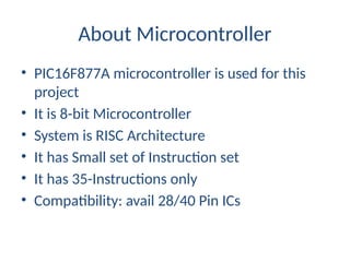
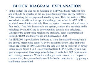
The document outlines a project focused on developing a prepaid energy meter using a PIC microcontroller, enabling the monitoring and controlling of energy consumption via a smart card system. This system aims to reduce power pilferage, streamline energy billing through automatic meter reading, and improve overall energy management for consumers and electricity providers. The project emphasizes the benefits of using prepaid meters, including customer flexibility, cost management, and energy conservation.
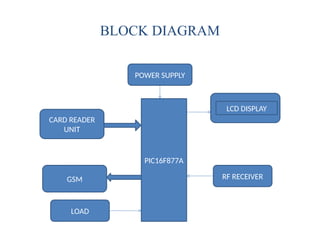
![Hardware Components
• Power supply[5v]
• PIC16F877A microcontroller
• GSM modem
• Current Transformer
• Voltage Transformer
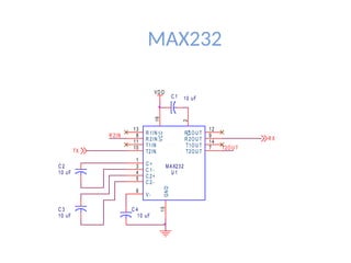
• Max232 – serial communication](https://image.slidesharecdn.com/129703339-prepaid-energy-meter-using-pic-microcontroller-250111110510-5e85fcab/85/129703339-Prepaid-Energy-Meter-Using-Pic-Microcontroller-pptx-9-320.jpg)