SlideShare a Scribd company logo
1 of 11
Download to read offline
PRACTICAL 
WIRELESS ETHERNET 
AND TCP/IP 
NETWORKING
1 
Introduction 
1.1 Overview 
Communication networks evolved due to the need to exchange and share information 
amongst a group of machines. During the last century many kinds of communication 
networks have been developed, such as telephone networks, computer networks and cable 
TV networks. 
With the need for data exchange superseding voice and picture transmission, computer 
networks have become the most prevalent of all communication networks. Depending on the 
distances between the computers, computer networks can be further differentiated into: 
• LANs (Local Area Networks)—These networks interconnect computers and 
other networked devices located a small distance apart, for instance computers in 
an office or building. The most popular LAN technology is Ethernet. 
• MANs (Metropolitan Area Networks)—These networks interconnect 
computers and other networked devices located at medium distances from each 
other, for instance around the perimeter of a large city. Technologies used here 
include Ethernet and FDDI. 
• WANs (Wide Area Networks)—These are interconnected LANs, located at 
large distances from each other, for instance in different cities or countries. 
Interconnection is via a ‘communications cloud’ that encompasses technologies 
such as SDH, ATM and X.25. 
• WLANs (Wireless LANs)—These are usually wireless extensions to an existing 
Ethernet network, the most popular being IEEE 802.11 (Wi-Fi). 
• PANs (Personal Area Networks)—These are networks connecting devices such 
as mobile phones, PDAs and laptops. They are typically spread over a few square 
meters or across a room at most, and use wireless technologies such as Bluetooth, 
Wireless USB or ZigBee. 
1.2 The OSI model 
A communication framework that has had a tremendous impact on the design of 
LANs/WLANs is the Open Systems Interconnection (OSI) model of the International 
Organization for Standardization (ISO). The objective of this model is to provide a 
framework for the co-ordination of standards development, and allows for existing as well as 
evolving standards activities to be set within that common framework.
2 Practical Wireless, Ethernet and TCP/IP Networking 
The various technologies described in this manual relate to different layers of the OSI model, 
for example: 
• IEEE 802.11(Wi-Fi): Physical layer (OSI layer 1) and MAC sub-layer of Data 
Link layer (lower half of OSI layer 2) 
• IEEE 802.2: LLC sub-layer of Data Link layer (upper half of OSI layer 2) 
• IEEE 802.3 (Ethernet): Same as Wi-Fi 
• IP: OSI layer 3 
• TCP: OSI layer 4 
• MODBUS Messaging Protocol: OSI layer 7 
For that reason a quick review of the OSI model basics is a necessity. 
1.2.1 Open and closed systems 
The interconnection of two or more devices with some form of digital communication is the 
first step towards establishing a network. In addition to the hardware requirements as 
discussed above, the software problems of communication must also be overcome. Where all 
the devices on a network are from the same manufacturer, the hardware and software 
problems are usually easily overcome because all the system components have usually been 
designed within the same guidelines and specifications. 
Proprietary networks that comprise hardware and software from only one vendor are called 
closed systems. In most cases these systems were developed at a time before standardization, 
or when it was considered unlikely that equipment from other manufacturers would be 
included in the network. 
In contrast, ‘open’ systems conform to specifications and guidelines that are ‘open’ to all. 
This allows equipment from any manufacturer that complies with that standard to be used 
interchangeably on the network. The benefits of open systems include wider availability of 
equipment, lower prices and easier integration with other components. 
1.2.2 The OSI concept 
Faced with the proliferation of closed network systems, the ISO defined a ‘Reference Model 
for Communication between Open Systems’ (ISO 7498) in 1978. This has since become 
known as the OSI model. The OSI model is essentially a data communications management 
structure that breaks data communications down into a manageable hierarchy (‘stack’) of 
seven layers. Each layer has a defined purpose and interfaces with the layers above it and 
below it. 
By laying down functions and services for each layer, some flexibility is allowed so that the 
system designers can develop protocols for each layer independently of each other. By 
conforming to the OSI standards, a system is able to communicate with any other compliant 
system, anywhere in the world. 
The OSI model supports a client/server model and since there must be at least two nodes to 
communicate, each layer also appears to converse with its peer layer at the other end of the 
communication channel in a virtual (‘logical’) manner. The concept of isolation of the 
process of each layer, together with standardized interfaces and peer-to-peer virtual 
communication, are fundamental to the concepts developed in a layered model such as the 
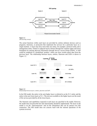
OSI model. This concept is shown in Figure 1.1.
Introduction 3 
Figure 1.1 
OSI layering concept 
The actual functions within each layer are provided by entities (abstract devices such as 
programs, functions, or protocols) that implement the services for a particular layer on a 
single machine. A layer may have more than one entity; for example a protocol entity and a 
management entity. Entities in adjacent layers interact through the common upper and lower 
boundaries by passing physical information through Service Access Points (SAPs). A SAP 
could be compared to a predefined ‘postbox’ where one layer would collect data from the 
previous layer. The relationship between layers, entities, functions and SAPs is shown in 
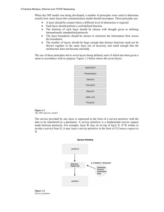
Figure 1.2. 
Figure 1.2 
Relationship between layers, entities, functions and SAPs 
In the OSI model, the entity in the next higher layer is referred to as the N+1 entity and the 
entity in the next lower layer as N–1. The services available to the higher layers are the result 
of the services provided by all the lower layers. 
The functions and capabilities expected at each layer are specified in the model. However, 
the model does not prescribe how this functionality should be implemented. The focus in the 
model is on the ‘interconnection’ and on the information that can be passed over this 
connection. The OSI model does not concern itself with the internal operations of the 
systems involved.
4 Practical Wireless, Ethernet and TCP/IP Networking 
When the OSI model was being developed, a number of principles were used to determine 
exactly how many layers this communication model should encompass. These principles are: 
• A layer should be created where a different level of abstraction is required 
• Each layer should perform a well-defined function 
• The function of each layer should be chosen with thought given to defining 
internationally standardized protocols 
• The layer boundaries should be chosen to minimize the information flow across 
the boundaries 
• The number of layers should be large enough that distinct functions need not be 
thrown together in the same layer out of necessity and small enough that the 
architecture does not become unwieldy 
The use of these principles led to seven layers being defined, each of which has been given a 
name in accordance with its purpose. Figure 1.3 below shows the seven layers. 
Figure 1.3 
The OSI reference model 
The service provided by any layer is expressed in the form of a service primitive with the 
data to be transferred as a parameter. A service primitive is a fundamental service request 
made between protocols. For example, layer W may sit on top of layer X. If W wishes to 
invoke a service from X, it may issue a service primitive in the form of X.Connect.request to 
X. 
Figure 1.4 
Service primitive
Introduction 5 
Typically, each layer in the transmitting stack, with the exception of the lowest, adds header 
information, or Protocol Control Information (PCI) – a.k.a. ‘header’, to the data before 
passing it across the interface to the next layer. This interface defines which primitive 
operations and services the lower layer offers to the upper one. The headers are used for 
peer-to-peer layer communication between the stacks and some layer implementations use 
the headers to invoke functions and services at the adjacent (N+1 or N-1) layers. 
At the transmitting stack, the user application (e.g. the client) invokes the process by passing 
data, primitive names and control information to the uppermost layer of the protocol stack. 
The stack then passes the data down through the layers of the stack, adding headers (and 
possibly trailers), and invoking functions in accordance with the rules of the protocol at each 
layer. 
At each layer, the ‘data’ received at a certain layer (including headers from the layers above 
it) is referred to as a Service Data Unit or SDU. This is normally prefixed with the first letter 
of the name of the layer. For example, the Transport layer receives a TSDU from the Session 
layer. The Transport layer then processes it, adds a header, and creates a Transport Protocol 
Data Unit or TPDU. 
At the receiving site, the opposite occurs with the headers being stripped from the data as it 
is passed up through the layers of the receiving stack. Generally speaking, layers in the same 
stack communicate with parameters passed through primitives, and peer layers communicate 
with the use of the headers across the network. 
At this stage it should be quite clear that there is no physical connection or direct 
communication between the peer layers of the communicating applications. Instead, all 
physical communication is across the lowest (Physical) layer of the stack. Communication 
takes place downwards through the protocol stack on the transmitting node and upwards 
through the receiving stack. Figure 1.4 shows the full architecture of the OSI model, whilst 
Figure 1.5 shows the effects of the addition of headers to the respective SDUs at each layer. 
The net effect of this extra information is to reduce the overall bandwidth of the 
communications channel, since some of the available bandwidth is used to pass control 
information (see also Figure 1.6). 
Figure 1.5 
Peer layer interaction in the OSI model
6 Practical Wireless, Ethernet and TCP/IP Networking 
Figure 1.6 
OSI message passing 
1.2.3 OSI layer services 
The services provided at each layer of the stack are as follows. 
Application layer 
The Application layer is the uppermost layer in the OSI reference model and is responsible 
for giving applications access to the protocol stack. Examples of Application-layer tasks 
include file transfer, electronic mail (e-mail) services, and network management. In order to 
accomplish its tasks, the Application layer passes program requests and data to the 
Presentation layer, which is responsible for encoding the Application layer’s data in the 
appropriate form. 
Presentation layer 
The Presentation layer is responsible for presenting information in a manner suitable for the 
applications or users dealing with the information. Functions such as data conversion from 
EBCDIC to ASCII (or vice versa), the use of special graphics or character sets, data 
compression or expansion, and data encryption or decryption are carried out at this layer. 
The presentation layer provides services for the Application layer above it, and uses the 
Session layer below it. In practice, the Presentation layer rarely appears in pure form, and it 
is the least well defined of the OSI layers. Application- or Session-layer programs often 
encompass some or all of the Presentation layer functions. 
Session layer 
The Session layer is responsible for synchronizing and sequencing the dialog and packets in 
a network connection. This layer is also responsible for ensuring that the connection is 
maintained until the transmission is complete, and that the appropriate security measures are 
taken during a ‘session’. The Session layer is used by the Presentation layer above it, and 
uses the Transport layer below it. 
Transport layer 
In the OSI reference model, the Transport layer is responsible for providing data transfer at 
an agreed-upon level of quality, such as at specified transmission speeds and error rates. To 
ensure delivery, some Transport layer protocols assign sequence numbers to outgoing 
packets. The Transport layer at the receiving end checks the packet numbers to make sure all 
have been delivered and to put the packet contents into the proper sequence for the recipient.
Introduction 7 
The Transport layer provides services for the Session layer above it, and uses the Network 
layer below it to find a route between source and destination. The Transport layer is crucial 
in many ways, because it sits between the upper layers, which are strongly application-dependent, 
and the lower one, which are network-based. 
The layers below the Transport layer are collectively known as the ‘subnet’ layers. 
Depending on how well (or not) they perform their functions; the Transport layer has to 
interfere less (or more) in order to maintain a reliable connection. 
Network layer 
The Network layer is the third layer from the bottom up, or the uppermost ‘subnet layer’. It 
is responsible for the following tasks: 
• Determining addresses or translating from hardware to network addresses. These 
addresses may be on a local network or they may refer to networks located 
elsewhere on an internetwork 
• Finding a route between a source and a destination node or between two 
intermediate devices 
• Fragmentation of large packets of data into frames small enough to be transmitted 
by the underlying Data Link layer (fragmentation). The corresponding Network 
layer at the receiving node undertakes reassembly of the packet 
Data link layer 
The Data Link layer is responsible for creating, transmitting, and receiving data packets. It 
provides services for the various protocols at the Network layer, and uses the Physical layer 
to transmit or receive material. The Data Link layer creates packets appropriate for the 
network architecture being used. Requests and data from the Network layer are part of the 
data in these packets (or frames, as they are often called at this layer). These frames are 
passed down to the Physical layer from where they are transmitted to the Physical layer on 
the destination host via the medium. Network architectures (such as Ethernet and Wi-Fi) 
typically encompass the Physical layer and the lower half of the Data Link layer. 
The IEEE 802 networking working groups have refined the Data Link layer into two sub-layers: 
• the Logical Link control (LLC) sub-layer in the upper half, implemented as IEEE 
802.2 and shared by several networking technologies such as IEEE 802.3 Ethernet, 
IEEE 802.5 Token Ring and IEEE 802.11Wi-Fi 
• the Media Access Control (MAC) sub-layer in the lower half, included with the 
Physical layer as part of the networking standards mentioned above 
The LLC sub-layer provides an interface for the Network layer protocols, and controls the 
logical communication with its peer at the receiving side. The MAC sub-layer controls 
physical access to the medium. 
Physical layer 
The Physical layer is the lowest layer in the OSI. This layer gets data packets from the Data 
Link layer above it, and converts the contents of these packets into a series of electrical 
signals that represent ‘0’ and ‘1’ values in a digital transmission. These signals are sent 
across a transmission medium to the Physical layer at the receiving end. At the destination, 
the Physical layer converts the electrical signals into a series of bit values. These values are 
grouped into packets and passed up to the Data Link layer. 
The required mechanical and electrical properties of the transmission medium are defined at 
this level. These include: 
• The type of cable and connectors used. The cable may be coaxial, twisted-pair, or 
fiber optic. The types of connectors depend on the type of cable 
• The pin assignments for the cable and connectors. Pin assignments depend on the 
type of cable and also on the network architecture being used
8 Practical Wireless, Ethernet and TCP/IP Networking 
• The format for the electrical signals. The encoding scheme used to signal ‘0’ and ‘1’ 
values in a digital transmission or particular values in an analog transmission 
depend on the network architecture being used 
The medium itself is, however, not specific here. For example, Fast Ethernet dictates Cat5 
cable, but the cable itself is specified in TIA/EIA-568B. 
1.2.4 Ethernet 
Ethernet is, at present, the dominant LAN technology. It provides a set of physical media 
definitions, a scheme for sharing that physical media (CSMA/CD or full duplex), and a 
simple frame format and hardware source/destination addressing scheme (MAC addresses) 
for moving packets of data between devices on a LAN. On its own, however, Ethernet lacks 
the more complex features required of a fully functional industrial network. For that reason, 
all installed Ethernet networks support one or more communication protocols that run on top 
of it, and provide more sophisticated data transfer and network management functionality. It 
is the higher layer protocols that determine what level of functionality is supported by the 
network, what types of devices may be connected to the network, and how devices 
interoperate on the network. 
For many years users have steered away from the use of Ethernet in industrial applications, 
mainly because of its perceived lack of determinism. This was due to the CSMA/CD 
medium access method, which is essentially stochastic in nature. Other issues that affected 
its industrial application included connectors and cabling, packaging, power supplies, 
switching requirements, speed, power over the cable requirements and provision for 
redundancy. 
Modern Ethernet systems, however, differ radically from the old cable-based legacy systems. 
Switched Ethernet systems now operate in full duplex mode, which, for all practical 
purposes, eliminates collisions. Many vendors offer industrial devices, with features such as 
IP67 environmental rating, rail mounting, redundant DC power supplies, VLAN capability, 
prioritized switching (IEEE 802.1p/Q) and redundant ring operation. 
Industry often expects device power to be delivered over the same wires as those used for 
communicating with the devices. The IEEE 802.3af standard allows a source device (a hub 
or a switch) to supply a minimum of 300 mA at 48 Volts DC to field devices. Other Ethernet 
developments include Virtual LANs (IEEE 802.1Q), prioritized switching (IEEE 802.1p) 
and redundant switched rings. 
1.2.5 TCP/IP 
The TCP/IP protocol suite consists of several protocols that provide routing services, end-to-end 
verification of transmitted data, and interfacing services to the stack for clients and 
servers. 
TCP is a connection-oriented transport (OSI layer 4) protocol and runs on the two end hosts; 
i.e. the client host and the server host. It is a very reliable protocol, using triple handshakes to 
establish connections, acknowledgements and timeouts plus retransmissions to ensure 
correct delivery of data, and sliding windows to prevent data buffer overruns on the 
receiving side. This comes at a cost, in terms of protocol overheads such as header size. 
UDP is a much simpler transport protocol. It is connectionless and provides a very simple 
capability to send ‘datagrams’ between two devices. It does not guarantee that the data will 
get from one device to another, does not perform retries, and does not even know if the target 
device has received the data successfully. 
Application layers that implement their own handshaking or connection management 
between two devices and, therefore, only need a minimal transport service, will use UDP.
Introduction 9 
UDP is smaller, simpler and faster than TCP due to its minimal capabilities and use of 
resources. In an industrial automation application, UDP is typically used for network 
management functions, applications that do not require reliable data transmission, 
applications that are willing to implement their own reliability scheme, such a flash memory 
programming of network devices, and for input/output (I/O) operations. 
1.2.6 Wireless LANs 
Traditional networks have been based on physical media, using extensive copper and fiber 
cabling to provide data, voice, and video transmission. However, the use of physical media is 
costly, unsuitable for rugged terrain, and limits mobility. 
In 1971 a group of researchers at the University of Hawaii created the first packet based 
radio communications network, ALOHANET. It was essentially the very first WLAN and 
consisted of several computers that communicated via a bi-directional star topology and 
spanned four of the Hawaiian Islands, with the central computer based on Oahu. 
In recent years more and more vendors have been developing wireless systems to support 
LAN, MAN and WAN infrastructures. The result has been the emergence of wireless 
networks. Current wireless technologies include Wi-Fi (IEEE 802.11b, a, g), IEEE 802.16 
(WiMax), small dish satellite (VSAT), mobile wireless and wireless PANs (Bluetooth, 
wireless USB and ZigBee), with Wi-Fi by far the most popular WLAN technology. 
There are numerous benefits in using wireless technologies, irrespective of the 
communication solution to be implemented. These include a high degree of mobility, 
accessibility and reduced installation costs.
10 Practical Wireless, Ethernet and TCP/IP Networking

More Related Content

What's hot

Fundamentals of Computer Networking
Fundamentals of Computer NetworkingFundamentals of Computer Networking
Fundamentals of Computer Networking
Pulkit Singhal
 
Types of computer networks
Types of computer networksTypes of computer networks
Types of computer networks
hemant Hrhemant5
 
Computer networks--osi model
Computer networks--osi modelComputer networks--osi model
Computer networks--osi model
Aditya Mehta
 

What's hot (20)

Wireless lan
Wireless lanWireless lan
Wireless lan
 
Firewall
FirewallFirewall
Firewall
 
Introduction to computer networks
Introduction to computer networksIntroduction to computer networks
Introduction to computer networks
 
Network architecture - part-I
Network architecture - part-INetwork architecture - part-I
Network architecture - part-I
 
Wman karna
Wman karnaWman karna
Wman karna
 
The Basics of Computer Networking
The Basics of Computer NetworkingThe Basics of Computer Networking
The Basics of Computer Networking
 
NETWORK COMPONENTS
NETWORK COMPONENTSNETWORK COMPONENTS
NETWORK COMPONENTS
 
Fundamentals of Computer Networking
Fundamentals of Computer NetworkingFundamentals of Computer Networking
Fundamentals of Computer Networking
 
Presentation On Computer Network
Presentation On Computer NetworkPresentation On Computer Network
Presentation On Computer Network
 
Introduction to Networks & Networking Concepts
Introduction to Networks & Networking ConceptsIntroduction to Networks & Networking Concepts
Introduction to Networks & Networking Concepts
 
Types of computer networks
Types of computer networksTypes of computer networks
Types of computer networks
 
Introduction to computer networks
Introduction to computer networksIntroduction to computer networks
Introduction to computer networks
 
Network Analysis & Designing
Network Analysis & DesigningNetwork Analysis & Designing
Network Analysis & Designing
 
Trends in Networking
Trends in NetworkingTrends in Networking
Trends in Networking
 
Networking Basics - Ferdon
Networking Basics - FerdonNetworking Basics - Ferdon
Networking Basics - Ferdon
 
Modern computer network technologies
Modern computer network technologies Modern computer network technologies
Modern computer network technologies
 
What is network architecture
What is network architecture What is network architecture
What is network architecture
 
Setting up a network
Setting up a networkSetting up a network
Setting up a network
 
Wlan wireless network
Wlan wireless networkWlan wireless network
Wlan wireless network
 
Computer networks--osi model
Computer networks--osi modelComputer networks--osi model
Computer networks--osi model
 

Viewers also liked

Wireless communication & adhoc networks
Wireless communication & adhoc networksWireless communication & adhoc networks
Wireless communication & adhoc networks
Salahuddin Jokhio
 
Mobile ad hoc network
Mobile ad hoc networkMobile ad hoc network
Mobile ad hoc network
skobu
 

Viewers also liked (14)

multiple access techniques used in wireless communication
multiple access techniques used in wireless communicationmultiple access techniques used in wireless communication
multiple access techniques used in wireless communication
 
Wireless communication & adhoc networks
Wireless communication & adhoc networksWireless communication & adhoc networks
Wireless communication & adhoc networks
 
FDMA TDMA
FDMA TDMAFDMA TDMA
FDMA TDMA
 
Multiple acces techniques
Multiple acces techniquesMultiple acces techniques
Multiple acces techniques
 
TDMA
TDMATDMA
TDMA
 
Wireless LAN technologies
Wireless LAN technologiesWireless LAN technologies
Wireless LAN technologies
 
Mobile Radio Propagations
Mobile Radio PropagationsMobile Radio Propagations
Mobile Radio Propagations
 
Bluetooth 1
Bluetooth 1Bluetooth 1
Bluetooth 1
 
Mobile ad hoc network
Mobile ad hoc networkMobile ad hoc network
Mobile ad hoc network
 
Manet
ManetManet
Manet
 
Ad-Hoc Networks
Ad-Hoc NetworksAd-Hoc Networks
Ad-Hoc Networks
 
Multiple access techniques for wireless communications
Multiple access techniques for wireless communicationsMultiple access techniques for wireless communications
Multiple access techniques for wireless communications
 
Free Download Powerpoint Slides
Free Download Powerpoint SlidesFree Download Powerpoint Slides
Free Download Powerpoint Slides
 
State of the Word 2011
State of the Word 2011State of the Word 2011
State of the Word 2011
 

Similar to Practical Wireless, Ethernet and TCP/IP Networking

Setting Up, Understanding & Troubleshooting of Industrial Ethernet & Automati...
Setting Up, Understanding & Troubleshooting of Industrial Ethernet & Automati...Setting Up, Understanding & Troubleshooting of Industrial Ethernet & Automati...
Setting Up, Understanding & Troubleshooting of Industrial Ethernet & Automati...
Living Online
 
Osi model
Osi modelOsi model
Osi model
ufaq kk
 
Networking overview
Networking overviewNetworking overview
Networking overview
maxminhaj1
 

Similar to Practical Wireless, Ethernet and TCP/IP Networking (20)

Setting Up, Understanding & Troubleshooting of Industrial Ethernet & Automati...
Setting Up, Understanding & Troubleshooting of Industrial Ethernet & Automati...Setting Up, Understanding & Troubleshooting of Industrial Ethernet & Automati...
Setting Up, Understanding & Troubleshooting of Industrial Ethernet & Automati...
 
What is network architecture (full)
What is network architecture (full)What is network architecture (full)
What is network architecture (full)
 
Osi
OsiOsi
Osi
 
Osi model
Osi model Osi model
Osi model
 
Lecture2
Lecture2Lecture2
Lecture2
 
Osi model
Osi modelOsi model
Osi model
 
Lecture2
Lecture2Lecture2
Lecture2
 
Osi model
Osi modelOsi model
Osi model
 
Osi model 1
Osi model 1Osi model 1
Osi model 1
 
OSI MODEL
    OSI MODEL    OSI MODEL
OSI MODEL
 
Lecture2
Lecture2Lecture2
Lecture2
 
Lecture2
Lecture2Lecture2
Lecture2
 
Osi model
Osi modelOsi model
Osi model
 
OSI MODEL
OSI MODELOSI MODEL
OSI MODEL
 
7 Layers OSI model description with 3 unofficial Layers.
7 Layers OSI model description with 3 unofficial Layers.7 Layers OSI model description with 3 unofficial Layers.
7 Layers OSI model description with 3 unofficial Layers.
 
OSI Model
OSI ModelOSI Model
OSI Model
 
Osi model
Osi modelOsi model
Osi model
 
Networking overview
Networking overviewNetworking overview
Networking overview
 
OSI models
OSI modelsOSI models
OSI models
 
Osi model
Osi modelOsi model
Osi model
 

More from Living Online

Practical Troubleshooting and Problem Solving of Modbus Protocols
Practical Troubleshooting and Problem Solving of Modbus ProtocolsPractical Troubleshooting and Problem Solving of Modbus Protocols
Practical Troubleshooting and Problem Solving of Modbus Protocols
Living Online
 
Practical Routers and Switches including TCI/IP and Ethernet for Engineers an...
Practical Routers and Switches including TCI/IP and Ethernet for Engineers an...Practical Routers and Switches including TCI/IP and Ethernet for Engineers an...
Practical Routers and Switches including TCI/IP and Ethernet for Engineers an...
Living Online
 
Practical Project Management for Engineers and Technicians
Practical Project Management for Engineers and TechniciansPractical Project Management for Engineers and Technicians
Practical Project Management for Engineers and Technicians
Living Online
 
Mechanical, Electrical and Instrumentation Engineering for Non-Engineers
Mechanical, Electrical and Instrumentation Engineering for Non-EngineersMechanical, Electrical and Instrumentation Engineering for Non-Engineers
Mechanical, Electrical and Instrumentation Engineering for Non-Engineers
Living Online
 
Hands on Data-Communication, Networking and TCP/IP Troubleshooting
Hands on Data-Communication, Networking and TCP/IP TroubleshootingHands on Data-Communication, Networking and TCP/IP Troubleshooting
Hands on Data-Communication, Networking and TCP/IP Troubleshooting
Living Online
 
Fundamentals of Instrumentation, Process Control, PLCs and SCADA for Plant Op...
Fundamentals of Instrumentation, Process Control, PLCs and SCADA for Plant Op...Fundamentals of Instrumentation, Process Control, PLCs and SCADA for Plant Op...
Fundamentals of Instrumentation, Process Control, PLCs and SCADA for Plant Op...
Living Online
 
Practical Fundamentals of Heating, Ventilation & Air-Conditioning (HVAC) for ...
Practical Fundamentals of Heating, Ventilation & Air-Conditioning (HVAC) for ...Practical Fundamentals of Heating, Ventilation & Air-Conditioning (HVAC) for ...
Practical Fundamentals of Heating, Ventilation & Air-Conditioning (HVAC) for ...
Living Online
 
Practical Energy Efficiency, Design, Engineering & Auditing
Practical Energy Efficiency, Design, Engineering & AuditingPractical Energy Efficiency, Design, Engineering & Auditing
Practical Energy Efficiency, Design, Engineering & Auditing
Living Online
 
High Voltage Electrical Compliance and Safety Operating Procedures
High Voltage Electrical Compliance and Safety Operating ProceduresHigh Voltage Electrical Compliance and Safety Operating Procedures
High Voltage Electrical Compliance and Safety Operating Procedures
Living Online
 
Practical Routers & Switches (Including TCPIP and Ethernet) for Engineers and...
Practical Routers & Switches (Including TCPIP and Ethernet) for Engineers and...Practical Routers & Switches (Including TCPIP and Ethernet) for Engineers and...
Practical Routers & Switches (Including TCPIP and Ethernet) for Engineers and...
Living Online
 
Cybersecurity for Automation Control and SCADA Systems
Cybersecurity for Automation Control and SCADA SystemsCybersecurity for Automation Control and SCADA Systems
Cybersecurity for Automation Control and SCADA Systems
Living Online
 
Inspection, Testing and Commissioning of Electrical Switchboards, Circuit Bre...
Inspection, Testing and Commissioning of Electrical Switchboards, Circuit Bre...Inspection, Testing and Commissioning of Electrical Switchboards, Circuit Bre...
Inspection, Testing and Commissioning of Electrical Switchboards, Circuit Bre...
Living Online
 
Practical Distribution & Substation Automation (Incl. Communications) for Ele...
Practical Distribution & Substation Automation (Incl. Communications) for Ele...Practical Distribution & Substation Automation (Incl. Communications) for Ele...
Practical Distribution & Substation Automation (Incl. Communications) for Ele...
Living Online
 
Practical Boiler Control & Instrumentation for Engineers & Technicians
Practical Boiler Control & Instrumentation for Engineers & TechniciansPractical Boiler Control & Instrumentation for Engineers & Technicians
Practical Boiler Control & Instrumentation for Engineers & Technicians
Living Online
 
Practical Arc Flash Protection for Electrical Safety Engineers and Technicians
Practical Arc Flash Protection for Electrical Safety Engineers and TechniciansPractical Arc Flash Protection for Electrical Safety Engineers and Technicians
Practical Arc Flash Protection for Electrical Safety Engineers and Technicians
Living Online
 
Practical Analytical Instrumentation in On-line Applications
Practical Analytical Instrumentation in On-line ApplicationsPractical Analytical Instrumentation in On-line Applications
Practical Analytical Instrumentation in On-line Applications
Living Online
 

More from Living Online (20)

Practical Troubleshooting and Problem Solving of Modbus Protocols
Practical Troubleshooting and Problem Solving of Modbus ProtocolsPractical Troubleshooting and Problem Solving of Modbus Protocols
Practical Troubleshooting and Problem Solving of Modbus Protocols
 
Practical Routers and Switches including TCI/IP and Ethernet for Engineers an...
Practical Routers and Switches including TCI/IP and Ethernet for Engineers an...Practical Routers and Switches including TCI/IP and Ethernet for Engineers an...
Practical Routers and Switches including TCI/IP and Ethernet for Engineers an...
 
Practical Project Management for Engineers and Technicians
Practical Project Management for Engineers and TechniciansPractical Project Management for Engineers and Technicians
Practical Project Management for Engineers and Technicians
 
Mechanical, Electrical and Instrumentation Engineering for Non-Engineers
Mechanical, Electrical and Instrumentation Engineering for Non-EngineersMechanical, Electrical and Instrumentation Engineering for Non-Engineers
Mechanical, Electrical and Instrumentation Engineering for Non-Engineers
 
Hands on Data-Communication, Networking and TCP/IP Troubleshooting
Hands on Data-Communication, Networking and TCP/IP TroubleshootingHands on Data-Communication, Networking and TCP/IP Troubleshooting
Hands on Data-Communication, Networking and TCP/IP Troubleshooting
 
Fundamentals of Instrumentation, Process Control, PLCs and SCADA for Plant Op...
Fundamentals of Instrumentation, Process Control, PLCs and SCADA for Plant Op...Fundamentals of Instrumentation, Process Control, PLCs and SCADA for Plant Op...
Fundamentals of Instrumentation, Process Control, PLCs and SCADA for Plant Op...
 
Practical Fundamentals of Heating, Ventilation & Air-Conditioning (HVAC) for ...
Practical Fundamentals of Heating, Ventilation & Air-Conditioning (HVAC) for ...Practical Fundamentals of Heating, Ventilation & Air-Conditioning (HVAC) for ...
Practical Fundamentals of Heating, Ventilation & Air-Conditioning (HVAC) for ...
 
Practical Energy Efficiency, Design, Engineering & Auditing
Practical Energy Efficiency, Design, Engineering & AuditingPractical Energy Efficiency, Design, Engineering & Auditing
Practical Energy Efficiency, Design, Engineering & Auditing
 
High Voltage Electrical Compliance and Safety Operating Procedures
High Voltage Electrical Compliance and Safety Operating ProceduresHigh Voltage Electrical Compliance and Safety Operating Procedures
High Voltage Electrical Compliance and Safety Operating Procedures
 
Practical Routers & Switches (Including TCPIP and Ethernet) for Engineers and...
Practical Routers & Switches (Including TCPIP and Ethernet) for Engineers and...Practical Routers & Switches (Including TCPIP and Ethernet) for Engineers and...
Practical Routers & Switches (Including TCPIP and Ethernet) for Engineers and...
 
Cybersecurity for Automation Control and SCADA Systems
Cybersecurity for Automation Control and SCADA SystemsCybersecurity for Automation Control and SCADA Systems
Cybersecurity for Automation Control and SCADA Systems
 
Practical Process Control
Practical Process ControlPractical Process Control
Practical Process Control
 
Inspection, Testing and Commissioning of Electrical Switchboards, Circuit Bre...
Inspection, Testing and Commissioning of Electrical Switchboards, Circuit Bre...Inspection, Testing and Commissioning of Electrical Switchboards, Circuit Bre...
Inspection, Testing and Commissioning of Electrical Switchboards, Circuit Bre...
 
Hands on Data Communications, Networking & TCP/IP Troubleshooting
Hands on Data Communications, Networking & TCP/IP TroubleshootingHands on Data Communications, Networking & TCP/IP Troubleshooting
Hands on Data Communications, Networking & TCP/IP Troubleshooting
 
Fundamentals of Instrumentation, Process Control, PLCs and SCADA for Plant Op...
Fundamentals of Instrumentation, Process Control, PLCs and SCADA for Plant Op...Fundamentals of Instrumentation, Process Control, PLCs and SCADA for Plant Op...
Fundamentals of Instrumentation, Process Control, PLCs and SCADA for Plant Op...
 
Practical Industrial Flow Measurement for Engineers and Technicians
Practical Industrial Flow Measurement for Engineers and TechniciansPractical Industrial Flow Measurement for Engineers and Technicians
Practical Industrial Flow Measurement for Engineers and Technicians
 
Practical Distribution & Substation Automation (Incl. Communications) for Ele...
Practical Distribution & Substation Automation (Incl. Communications) for Ele...Practical Distribution & Substation Automation (Incl. Communications) for Ele...
Practical Distribution & Substation Automation (Incl. Communications) for Ele...
 
Practical Boiler Control & Instrumentation for Engineers & Technicians
Practical Boiler Control & Instrumentation for Engineers & TechniciansPractical Boiler Control & Instrumentation for Engineers & Technicians
Practical Boiler Control & Instrumentation for Engineers & Technicians
 
Practical Arc Flash Protection for Electrical Safety Engineers and Technicians
Practical Arc Flash Protection for Electrical Safety Engineers and TechniciansPractical Arc Flash Protection for Electrical Safety Engineers and Technicians
Practical Arc Flash Protection for Electrical Safety Engineers and Technicians
 
Practical Analytical Instrumentation in On-line Applications
Practical Analytical Instrumentation in On-line ApplicationsPractical Analytical Instrumentation in On-line Applications
Practical Analytical Instrumentation in On-line Applications
 

Recently uploaded

Cara Menggugurkan Sperma Yang Masuk Rahim Biyar Tidak Hamil
Cara Menggugurkan Sperma Yang Masuk Rahim Biyar Tidak HamilCara Menggugurkan Sperma Yang Masuk Rahim Biyar Tidak Hamil
Cara Menggugurkan Sperma Yang Masuk Rahim Biyar Tidak Hamil
Cara Menggugurkan Kandungan 087776558899
 
Kuwait City MTP kit ((+919101817206)) Buy Abortion Pills Kuwait
Kuwait City MTP kit ((+919101817206)) Buy Abortion Pills KuwaitKuwait City MTP kit ((+919101817206)) Buy Abortion Pills Kuwait
Kuwait City MTP kit ((+919101817206)) Buy Abortion Pills Kuwait
jaanualu31
 
Standard vs Custom Battery Packs - Decoding the Power Play
Standard vs Custom Battery Packs - Decoding the Power PlayStandard vs Custom Battery Packs - Decoding the Power Play
Standard vs Custom Battery Packs - Decoding the Power Play
Epec Engineered Technologies
 
Introduction to Robotics in Mechanical Engineering.pptx
Introduction to Robotics in Mechanical Engineering.pptxIntroduction to Robotics in Mechanical Engineering.pptx
Introduction to Robotics in Mechanical Engineering.pptx
hublikarsn
 
Digital Communication Essentials: DPCM, DM, and ADM .pptx
Digital Communication Essentials: DPCM, DM, and ADM .pptxDigital Communication Essentials: DPCM, DM, and ADM .pptx
Digital Communication Essentials: DPCM, DM, and ADM .pptx
pritamlangde
 
XXXXXXXXXXXXXXXXXXXXXXXXXXXXXXXXXXXXXXXXXXXXXXXXXXXX
XXXXXXXXXXXXXXXXXXXXXXXXXXXXXXXXXXXXXXXXXXXXXXXXXXXXXXXXXXXXXXXXXXXXXXXXXXXXXXXXXXXXXXXXXXXXXXXXXXXXXXXX
XXXXXXXXXXXXXXXXXXXXXXXXXXXXXXXXXXXXXXXXXXXXXXXXXXXX
ssuser89054b
 

Recently uploaded (20)

Cara Menggugurkan Sperma Yang Masuk Rahim Biyar Tidak Hamil
Cara Menggugurkan Sperma Yang Masuk Rahim Biyar Tidak HamilCara Menggugurkan Sperma Yang Masuk Rahim Biyar Tidak Hamil
Cara Menggugurkan Sperma Yang Masuk Rahim Biyar Tidak Hamil
 
Online electricity billing project report..pdf
Online electricity billing project report..pdfOnline electricity billing project report..pdf
Online electricity billing project report..pdf
 
Convergence of Robotics and Gen AI offers excellent opportunities for Entrepr...
Convergence of Robotics and Gen AI offers excellent opportunities for Entrepr...Convergence of Robotics and Gen AI offers excellent opportunities for Entrepr...
Convergence of Robotics and Gen AI offers excellent opportunities for Entrepr...
 
Kuwait City MTP kit ((+919101817206)) Buy Abortion Pills Kuwait
Kuwait City MTP kit ((+919101817206)) Buy Abortion Pills KuwaitKuwait City MTP kit ((+919101817206)) Buy Abortion Pills Kuwait
Kuwait City MTP kit ((+919101817206)) Buy Abortion Pills Kuwait
 
Path loss model, OKUMURA Model, Hata Model
Path loss model, OKUMURA Model, Hata ModelPath loss model, OKUMURA Model, Hata Model
Path loss model, OKUMURA Model, Hata Model
 
Standard vs Custom Battery Packs - Decoding the Power Play
Standard vs Custom Battery Packs - Decoding the Power PlayStandard vs Custom Battery Packs - Decoding the Power Play
Standard vs Custom Battery Packs - Decoding the Power Play
 
Worksharing and 3D Modeling with Revit.pptx
Worksharing and 3D Modeling with Revit.pptxWorksharing and 3D Modeling with Revit.pptx
Worksharing and 3D Modeling with Revit.pptx
 
Online food ordering system project report.pdf
Online food ordering system project report.pdfOnline food ordering system project report.pdf
Online food ordering system project report.pdf
 
Introduction to Robotics in Mechanical Engineering.pptx
Introduction to Robotics in Mechanical Engineering.pptxIntroduction to Robotics in Mechanical Engineering.pptx
Introduction to Robotics in Mechanical Engineering.pptx
 
Hostel management system project report..pdf
Hostel management system project report..pdfHostel management system project report..pdf
Hostel management system project report..pdf
 
Introduction to Artificial Intelligence ( AI)
Introduction to Artificial Intelligence ( AI)Introduction to Artificial Intelligence ( AI)
Introduction to Artificial Intelligence ( AI)
 
Signal Processing and Linear System Analysis
Signal Processing and Linear System AnalysisSignal Processing and Linear System Analysis
Signal Processing and Linear System Analysis
 
Digital Communication Essentials: DPCM, DM, and ADM .pptx
Digital Communication Essentials: DPCM, DM, and ADM .pptxDigital Communication Essentials: DPCM, DM, and ADM .pptx
Digital Communication Essentials: DPCM, DM, and ADM .pptx
 
XXXXXXXXXXXXXXXXXXXXXXXXXXXXXXXXXXXXXXXXXXXXXXXXXXXX
XXXXXXXXXXXXXXXXXXXXXXXXXXXXXXXXXXXXXXXXXXXXXXXXXXXXXXXXXXXXXXXXXXXXXXXXXXXXXXXXXXXXXXXXXXXXXXXXXXXXXXXX
XXXXXXXXXXXXXXXXXXXXXXXXXXXXXXXXXXXXXXXXXXXXXXXXXXXX
 
AIRCANVAS[1].pdf mini project for btech students
AIRCANVAS[1].pdf mini project for btech studentsAIRCANVAS[1].pdf mini project for btech students
AIRCANVAS[1].pdf mini project for btech students
 
COST-EFFETIVE and Energy Efficient BUILDINGS ptx
COST-EFFETIVE  and Energy Efficient BUILDINGS ptxCOST-EFFETIVE  and Energy Efficient BUILDINGS ptx
COST-EFFETIVE and Energy Efficient BUILDINGS ptx
 
Augmented Reality (AR) with Augin Software.pptx
Augmented Reality (AR) with Augin Software.pptxAugmented Reality (AR) with Augin Software.pptx
Augmented Reality (AR) with Augin Software.pptx
 
Introduction to Geographic Information Systems
Introduction to Geographic Information SystemsIntroduction to Geographic Information Systems
Introduction to Geographic Information Systems
 
8086 Microprocessor Architecture: 16-bit microprocessor
8086 Microprocessor Architecture: 16-bit microprocessor8086 Microprocessor Architecture: 16-bit microprocessor
8086 Microprocessor Architecture: 16-bit microprocessor
 
Introduction to Serverless with AWS Lambda
Introduction to Serverless with AWS LambdaIntroduction to Serverless with AWS Lambda
Introduction to Serverless with AWS Lambda
 

Practical Wireless, Ethernet and TCP/IP Networking

  • 1. PRACTICAL WIRELESS ETHERNET AND TCP/IP NETWORKING
  • 2. 1 Introduction 1.1 Overview Communication networks evolved due to the need to exchange and share information amongst a group of machines. During the last century many kinds of communication networks have been developed, such as telephone networks, computer networks and cable TV networks. With the need for data exchange superseding voice and picture transmission, computer networks have become the most prevalent of all communication networks. Depending on the distances between the computers, computer networks can be further differentiated into: • LANs (Local Area Networks)—These networks interconnect computers and other networked devices located a small distance apart, for instance computers in an office or building. The most popular LAN technology is Ethernet. • MANs (Metropolitan Area Networks)—These networks interconnect computers and other networked devices located at medium distances from each other, for instance around the perimeter of a large city. Technologies used here include Ethernet and FDDI. • WANs (Wide Area Networks)—These are interconnected LANs, located at large distances from each other, for instance in different cities or countries. Interconnection is via a ‘communications cloud’ that encompasses technologies such as SDH, ATM and X.25. • WLANs (Wireless LANs)—These are usually wireless extensions to an existing Ethernet network, the most popular being IEEE 802.11 (Wi-Fi). • PANs (Personal Area Networks)—These are networks connecting devices such as mobile phones, PDAs and laptops. They are typically spread over a few square meters or across a room at most, and use wireless technologies such as Bluetooth, Wireless USB or ZigBee. 1.2 The OSI model A communication framework that has had a tremendous impact on the design of LANs/WLANs is the Open Systems Interconnection (OSI) model of the International Organization for Standardization (ISO). The objective of this model is to provide a framework for the co-ordination of standards development, and allows for existing as well as evolving standards activities to be set within that common framework.
  • 3. 2 Practical Wireless, Ethernet and TCP/IP Networking The various technologies described in this manual relate to different layers of the OSI model, for example: • IEEE 802.11(Wi-Fi): Physical layer (OSI layer 1) and MAC sub-layer of Data Link layer (lower half of OSI layer 2) • IEEE 802.2: LLC sub-layer of Data Link layer (upper half of OSI layer 2) • IEEE 802.3 (Ethernet): Same as Wi-Fi • IP: OSI layer 3 • TCP: OSI layer 4 • MODBUS Messaging Protocol: OSI layer 7 For that reason a quick review of the OSI model basics is a necessity. 1.2.1 Open and closed systems The interconnection of two or more devices with some form of digital communication is the first step towards establishing a network. In addition to the hardware requirements as discussed above, the software problems of communication must also be overcome. Where all the devices on a network are from the same manufacturer, the hardware and software problems are usually easily overcome because all the system components have usually been designed within the same guidelines and specifications. Proprietary networks that comprise hardware and software from only one vendor are called closed systems. In most cases these systems were developed at a time before standardization, or when it was considered unlikely that equipment from other manufacturers would be included in the network. In contrast, ‘open’ systems conform to specifications and guidelines that are ‘open’ to all. This allows equipment from any manufacturer that complies with that standard to be used interchangeably on the network. The benefits of open systems include wider availability of equipment, lower prices and easier integration with other components. 1.2.2 The OSI concept Faced with the proliferation of closed network systems, the ISO defined a ‘Reference Model for Communication between Open Systems’ (ISO 7498) in 1978. This has since become known as the OSI model. The OSI model is essentially a data communications management structure that breaks data communications down into a manageable hierarchy (‘stack’) of seven layers. Each layer has a defined purpose and interfaces with the layers above it and below it. By laying down functions and services for each layer, some flexibility is allowed so that the system designers can develop protocols for each layer independently of each other. By conforming to the OSI standards, a system is able to communicate with any other compliant system, anywhere in the world. The OSI model supports a client/server model and since there must be at least two nodes to communicate, each layer also appears to converse with its peer layer at the other end of the communication channel in a virtual (‘logical’) manner. The concept of isolation of the process of each layer, together with standardized interfaces and peer-to-peer virtual communication, are fundamental to the concepts developed in a layered model such as the OSI model. This concept is shown in Figure 1.1.
  • 4. Introduction 3 Figure 1.1 OSI layering concept The actual functions within each layer are provided by entities (abstract devices such as programs, functions, or protocols) that implement the services for a particular layer on a single machine. A layer may have more than one entity; for example a protocol entity and a management entity. Entities in adjacent layers interact through the common upper and lower boundaries by passing physical information through Service Access Points (SAPs). A SAP could be compared to a predefined ‘postbox’ where one layer would collect data from the previous layer. The relationship between layers, entities, functions and SAPs is shown in Figure 1.2. Figure 1.2 Relationship between layers, entities, functions and SAPs In the OSI model, the entity in the next higher layer is referred to as the N+1 entity and the entity in the next lower layer as N–1. The services available to the higher layers are the result of the services provided by all the lower layers. The functions and capabilities expected at each layer are specified in the model. However, the model does not prescribe how this functionality should be implemented. The focus in the model is on the ‘interconnection’ and on the information that can be passed over this connection. The OSI model does not concern itself with the internal operations of the systems involved.
  • 5. 4 Practical Wireless, Ethernet and TCP/IP Networking When the OSI model was being developed, a number of principles were used to determine exactly how many layers this communication model should encompass. These principles are: • A layer should be created where a different level of abstraction is required • Each layer should perform a well-defined function • The function of each layer should be chosen with thought given to defining internationally standardized protocols • The layer boundaries should be chosen to minimize the information flow across the boundaries • The number of layers should be large enough that distinct functions need not be thrown together in the same layer out of necessity and small enough that the architecture does not become unwieldy The use of these principles led to seven layers being defined, each of which has been given a name in accordance with its purpose. Figure 1.3 below shows the seven layers. Figure 1.3 The OSI reference model The service provided by any layer is expressed in the form of a service primitive with the data to be transferred as a parameter. A service primitive is a fundamental service request made between protocols. For example, layer W may sit on top of layer X. If W wishes to invoke a service from X, it may issue a service primitive in the form of X.Connect.request to X. Figure 1.4 Service primitive
  • 6. Introduction 5 Typically, each layer in the transmitting stack, with the exception of the lowest, adds header information, or Protocol Control Information (PCI) – a.k.a. ‘header’, to the data before passing it across the interface to the next layer. This interface defines which primitive operations and services the lower layer offers to the upper one. The headers are used for peer-to-peer layer communication between the stacks and some layer implementations use the headers to invoke functions and services at the adjacent (N+1 or N-1) layers. At the transmitting stack, the user application (e.g. the client) invokes the process by passing data, primitive names and control information to the uppermost layer of the protocol stack. The stack then passes the data down through the layers of the stack, adding headers (and possibly trailers), and invoking functions in accordance with the rules of the protocol at each layer. At each layer, the ‘data’ received at a certain layer (including headers from the layers above it) is referred to as a Service Data Unit or SDU. This is normally prefixed with the first letter of the name of the layer. For example, the Transport layer receives a TSDU from the Session layer. The Transport layer then processes it, adds a header, and creates a Transport Protocol Data Unit or TPDU. At the receiving site, the opposite occurs with the headers being stripped from the data as it is passed up through the layers of the receiving stack. Generally speaking, layers in the same stack communicate with parameters passed through primitives, and peer layers communicate with the use of the headers across the network. At this stage it should be quite clear that there is no physical connection or direct communication between the peer layers of the communicating applications. Instead, all physical communication is across the lowest (Physical) layer of the stack. Communication takes place downwards through the protocol stack on the transmitting node and upwards through the receiving stack. Figure 1.4 shows the full architecture of the OSI model, whilst Figure 1.5 shows the effects of the addition of headers to the respective SDUs at each layer. The net effect of this extra information is to reduce the overall bandwidth of the communications channel, since some of the available bandwidth is used to pass control information (see also Figure 1.6). Figure 1.5 Peer layer interaction in the OSI model
  • 7. 6 Practical Wireless, Ethernet and TCP/IP Networking Figure 1.6 OSI message passing 1.2.3 OSI layer services The services provided at each layer of the stack are as follows. Application layer The Application layer is the uppermost layer in the OSI reference model and is responsible for giving applications access to the protocol stack. Examples of Application-layer tasks include file transfer, electronic mail (e-mail) services, and network management. In order to accomplish its tasks, the Application layer passes program requests and data to the Presentation layer, which is responsible for encoding the Application layer’s data in the appropriate form. Presentation layer The Presentation layer is responsible for presenting information in a manner suitable for the applications or users dealing with the information. Functions such as data conversion from EBCDIC to ASCII (or vice versa), the use of special graphics or character sets, data compression or expansion, and data encryption or decryption are carried out at this layer. The presentation layer provides services for the Application layer above it, and uses the Session layer below it. In practice, the Presentation layer rarely appears in pure form, and it is the least well defined of the OSI layers. Application- or Session-layer programs often encompass some or all of the Presentation layer functions. Session layer The Session layer is responsible for synchronizing and sequencing the dialog and packets in a network connection. This layer is also responsible for ensuring that the connection is maintained until the transmission is complete, and that the appropriate security measures are taken during a ‘session’. The Session layer is used by the Presentation layer above it, and uses the Transport layer below it. Transport layer In the OSI reference model, the Transport layer is responsible for providing data transfer at an agreed-upon level of quality, such as at specified transmission speeds and error rates. To ensure delivery, some Transport layer protocols assign sequence numbers to outgoing packets. The Transport layer at the receiving end checks the packet numbers to make sure all have been delivered and to put the packet contents into the proper sequence for the recipient.
  • 8. Introduction 7 The Transport layer provides services for the Session layer above it, and uses the Network layer below it to find a route between source and destination. The Transport layer is crucial in many ways, because it sits between the upper layers, which are strongly application-dependent, and the lower one, which are network-based. The layers below the Transport layer are collectively known as the ‘subnet’ layers. Depending on how well (or not) they perform their functions; the Transport layer has to interfere less (or more) in order to maintain a reliable connection. Network layer The Network layer is the third layer from the bottom up, or the uppermost ‘subnet layer’. It is responsible for the following tasks: • Determining addresses or translating from hardware to network addresses. These addresses may be on a local network or they may refer to networks located elsewhere on an internetwork • Finding a route between a source and a destination node or between two intermediate devices • Fragmentation of large packets of data into frames small enough to be transmitted by the underlying Data Link layer (fragmentation). The corresponding Network layer at the receiving node undertakes reassembly of the packet Data link layer The Data Link layer is responsible for creating, transmitting, and receiving data packets. It provides services for the various protocols at the Network layer, and uses the Physical layer to transmit or receive material. The Data Link layer creates packets appropriate for the network architecture being used. Requests and data from the Network layer are part of the data in these packets (or frames, as they are often called at this layer). These frames are passed down to the Physical layer from where they are transmitted to the Physical layer on the destination host via the medium. Network architectures (such as Ethernet and Wi-Fi) typically encompass the Physical layer and the lower half of the Data Link layer. The IEEE 802 networking working groups have refined the Data Link layer into two sub-layers: • the Logical Link control (LLC) sub-layer in the upper half, implemented as IEEE 802.2 and shared by several networking technologies such as IEEE 802.3 Ethernet, IEEE 802.5 Token Ring and IEEE 802.11Wi-Fi • the Media Access Control (MAC) sub-layer in the lower half, included with the Physical layer as part of the networking standards mentioned above The LLC sub-layer provides an interface for the Network layer protocols, and controls the logical communication with its peer at the receiving side. The MAC sub-layer controls physical access to the medium. Physical layer The Physical layer is the lowest layer in the OSI. This layer gets data packets from the Data Link layer above it, and converts the contents of these packets into a series of electrical signals that represent ‘0’ and ‘1’ values in a digital transmission. These signals are sent across a transmission medium to the Physical layer at the receiving end. At the destination, the Physical layer converts the electrical signals into a series of bit values. These values are grouped into packets and passed up to the Data Link layer. The required mechanical and electrical properties of the transmission medium are defined at this level. These include: • The type of cable and connectors used. The cable may be coaxial, twisted-pair, or fiber optic. The types of connectors depend on the type of cable • The pin assignments for the cable and connectors. Pin assignments depend on the type of cable and also on the network architecture being used
  • 9. 8 Practical Wireless, Ethernet and TCP/IP Networking • The format for the electrical signals. The encoding scheme used to signal ‘0’ and ‘1’ values in a digital transmission or particular values in an analog transmission depend on the network architecture being used The medium itself is, however, not specific here. For example, Fast Ethernet dictates Cat5 cable, but the cable itself is specified in TIA/EIA-568B. 1.2.4 Ethernet Ethernet is, at present, the dominant LAN technology. It provides a set of physical media definitions, a scheme for sharing that physical media (CSMA/CD or full duplex), and a simple frame format and hardware source/destination addressing scheme (MAC addresses) for moving packets of data between devices on a LAN. On its own, however, Ethernet lacks the more complex features required of a fully functional industrial network. For that reason, all installed Ethernet networks support one or more communication protocols that run on top of it, and provide more sophisticated data transfer and network management functionality. It is the higher layer protocols that determine what level of functionality is supported by the network, what types of devices may be connected to the network, and how devices interoperate on the network. For many years users have steered away from the use of Ethernet in industrial applications, mainly because of its perceived lack of determinism. This was due to the CSMA/CD medium access method, which is essentially stochastic in nature. Other issues that affected its industrial application included connectors and cabling, packaging, power supplies, switching requirements, speed, power over the cable requirements and provision for redundancy. Modern Ethernet systems, however, differ radically from the old cable-based legacy systems. Switched Ethernet systems now operate in full duplex mode, which, for all practical purposes, eliminates collisions. Many vendors offer industrial devices, with features such as IP67 environmental rating, rail mounting, redundant DC power supplies, VLAN capability, prioritized switching (IEEE 802.1p/Q) and redundant ring operation. Industry often expects device power to be delivered over the same wires as those used for communicating with the devices. The IEEE 802.3af standard allows a source device (a hub or a switch) to supply a minimum of 300 mA at 48 Volts DC to field devices. Other Ethernet developments include Virtual LANs (IEEE 802.1Q), prioritized switching (IEEE 802.1p) and redundant switched rings. 1.2.5 TCP/IP The TCP/IP protocol suite consists of several protocols that provide routing services, end-to-end verification of transmitted data, and interfacing services to the stack for clients and servers. TCP is a connection-oriented transport (OSI layer 4) protocol and runs on the two end hosts; i.e. the client host and the server host. It is a very reliable protocol, using triple handshakes to establish connections, acknowledgements and timeouts plus retransmissions to ensure correct delivery of data, and sliding windows to prevent data buffer overruns on the receiving side. This comes at a cost, in terms of protocol overheads such as header size. UDP is a much simpler transport protocol. It is connectionless and provides a very simple capability to send ‘datagrams’ between two devices. It does not guarantee that the data will get from one device to another, does not perform retries, and does not even know if the target device has received the data successfully. Application layers that implement their own handshaking or connection management between two devices and, therefore, only need a minimal transport service, will use UDP.
  • 10. Introduction 9 UDP is smaller, simpler and faster than TCP due to its minimal capabilities and use of resources. In an industrial automation application, UDP is typically used for network management functions, applications that do not require reliable data transmission, applications that are willing to implement their own reliability scheme, such a flash memory programming of network devices, and for input/output (I/O) operations. 1.2.6 Wireless LANs Traditional networks have been based on physical media, using extensive copper and fiber cabling to provide data, voice, and video transmission. However, the use of physical media is costly, unsuitable for rugged terrain, and limits mobility. In 1971 a group of researchers at the University of Hawaii created the first packet based radio communications network, ALOHANET. It was essentially the very first WLAN and consisted of several computers that communicated via a bi-directional star topology and spanned four of the Hawaiian Islands, with the central computer based on Oahu. In recent years more and more vendors have been developing wireless systems to support LAN, MAN and WAN infrastructures. The result has been the emergence of wireless networks. Current wireless technologies include Wi-Fi (IEEE 802.11b, a, g), IEEE 802.16 (WiMax), small dish satellite (VSAT), mobile wireless and wireless PANs (Bluetooth, wireless USB and ZigBee), with Wi-Fi by far the most popular WLAN technology. There are numerous benefits in using wireless technologies, irrespective of the communication solution to be implemented. These include a high degree of mobility, accessibility and reduced installation costs.
  • 11. 10 Practical Wireless, Ethernet and TCP/IP Networking