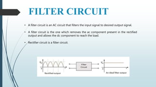
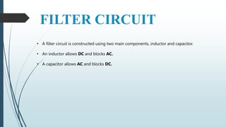
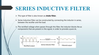
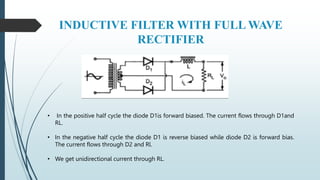
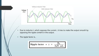
INDUCTOR FILTER
NAME : B SANMAYI
ROLL NUMBER : 22911A04D8
CLASS : ECE-C
SUBJECT : EDC
FILTER CIRCUIT
• A filter circuit is an AC circuit that filters the input signal to desired output signal.
• A filter circuit is the one which removes the ac component present in the rectified
output and allows the dc component to reach the load.
• Rectifier circuit is a filter circuit.
FILTER CIRCUIT
• A filter circuit is constructed using two main components, inductor and capacitor.
• An inductor allows DC and blocks AC.
• A capacitor allows AC and blocks DC.
SERIES INDUCTIVE FILTER
 This type of filter is also known as choke filter.
 Series Inductive Filter can be constructed by connecting the inductor in series,
between the rectifier and the load.
 The rectified voltage when passes through this filter, the inductor blocks the ac
components that are present in the signal, in order to provide a pure dc,
INDUCTIVE FILTER WITH FULL WAVE
RECTIFIER
• In the positive half cycle the diode D1is forward biased. The current flows through D1and
RL.
• In the negative half cycle the diode D1 is reverse biased while diode D2 is forward bias.
The current flows through D2 and Rl.
• We get unidirectional current through RL.
• Due to inductor L which opposes the current , it tries to make the output smooth by
opposing the ripple content in the output.
• The ripple factor is ,
ADVANTAGES
 The series inductor filter reduces the ripple in the DC output of rectifier circuit.
 It has no surge current through diode.
 It has low ripple factor at heavy load currents
 It’s relatively simple and inexpensive to implement.
DISADVANTAGES
 It gives low output DC voltage for larger value of inductance.
 It has poor voltage regulation.
 It can be affected by the parasitic capacitance of the inductor.
 It is not suitable for low voltage power supplies.
THANK YOU

PPT on series inductive filter

  • 1.
    INDUCTOR FILTER NAME :B SANMAYI ROLL NUMBER : 22911A04D8 CLASS : ECE-C SUBJECT : EDC
  • 2.
    FILTER CIRCUIT • Afilter circuit is an AC circuit that filters the input signal to desired output signal. • A filter circuit is the one which removes the ac component present in the rectified output and allows the dc component to reach the load. • Rectifier circuit is a filter circuit.
  • 3.
    FILTER CIRCUIT • Afilter circuit is constructed using two main components, inductor and capacitor. • An inductor allows DC and blocks AC. • A capacitor allows AC and blocks DC.
  • 4.
    SERIES INDUCTIVE FILTER This type of filter is also known as choke filter.  Series Inductive Filter can be constructed by connecting the inductor in series, between the rectifier and the load.  The rectified voltage when passes through this filter, the inductor blocks the ac components that are present in the signal, in order to provide a pure dc,
  • 5.
    INDUCTIVE FILTER WITHFULL WAVE RECTIFIER • In the positive half cycle the diode D1is forward biased. The current flows through D1and RL. • In the negative half cycle the diode D1 is reverse biased while diode D2 is forward bias. The current flows through D2 and Rl. • We get unidirectional current through RL.
  • 6.
    • Due toinductor L which opposes the current , it tries to make the output smooth by opposing the ripple content in the output. • The ripple factor is ,
  • 7.
    ADVANTAGES  The seriesinductor filter reduces the ripple in the DC output of rectifier circuit.  It has no surge current through diode.  It has low ripple factor at heavy load currents  It’s relatively simple and inexpensive to implement.
  • 8.
    DISADVANTAGES  It giveslow output DC voltage for larger value of inductance.  It has poor voltage regulation.  It can be affected by the parasitic capacitance of the inductor.  It is not suitable for low voltage power supplies.
  • 9.