Downloaded 281 times

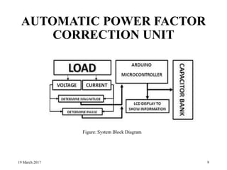
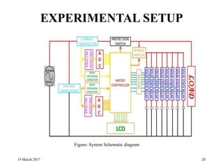
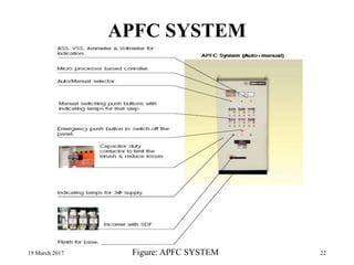


This document discusses automatic power factor correction units. It begins by explaining what power factor is and how inductive loads can cause low power factors. It then describes why power factors should be improved, such as reducing energy losses. The document outlines different methods to correct power factor, and why automatic correction is needed since loads and power factors vary. It provides details on how an automatic power factor correction unit works, including using sensors to measure voltage, current and power factor, and switching capacitors in or out to maintain a high power factor. In conclusion, automatic power factor correction can improve efficiency and minimize line losses for industrial and commercial facilities.