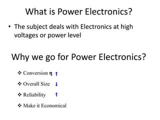
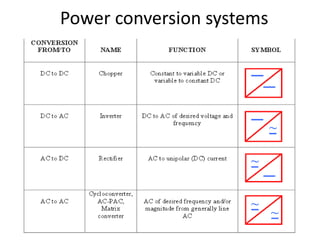
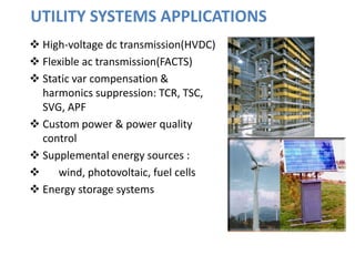
Power Electronics and its
applications
Presented by
R.Reddy Prasad
Assistant professor
Dept. of EEE.
What is Power Electronics?
• The subject deals with Electronics at high
voltages or power level
Why we go for Power Electronics?
 Conversion 𝝶
 Overall Size
 Reliability
 Make it Economical
Thermal Power plant
In India major Power Comes from Thermal Power plants (70%)
Losses Associated in Thermal Power Generation
Boiler
Turbine
Generator
Chemical Energy Input (100 BTU )
Thermal Energy (88 BTU )
Mech. Energy (36 BTU )
Elec. Energy Output (10.26 Wh )
Efficiency = 29% (with out MHD) Efficiency = 35% (with MHD)
BY USING POWER ELECTRONICS
Transmission Efficiency 𝝶 Utilization Efficiency 𝝶
Distribution Efficiency 𝝶 Renewables Generation 𝝶
Maximum power Transfer Stability
Power conversion systems
APPLICATIONS
Industrial
Transportation
Utility systems
Power supplies for all kinds of electronic
equipment
Residential and home appliances
Space technology
Other applications
INDUSTRIAL APPLICATIONS
 Motor drives
 Electrolysis
 Electroplating
 Induction heating
 Welding
 Arc furnaces and ovens
 Lighting
TRANSPORTATION APPLICATIONS
 Trains & locomotives
 Subways
 Trolley buses
 Magnetic levitation
 Electric vehicles
 Automotive electronics
 Ship power systems
 Aircraft power systems
UTILITY SYSTEMS APPLICATIONS
 High-voltage dc transmission(HVDC)
 Flexible ac transmission(FACTS)
 Static var compensation &
harmonics suppression: TCR, TSC,
SVG, APF
 Custom power & power quality
control
 Supplemental energy sources :
 wind, photovoltaic, fuel cells
 Energy storage systems
POWER SUPPLIES FOR ELECTRONIC EQUIPMENT
 Telecommunications
 Computers
 Office equipment
 Electronic instruments
 Portable or mobile
electronics
server
computer
Telecommunication
RESIDENTIAL AND HOME APPLIANCES
 Lighting
 Heating
 Air conditioning
 Refrigeration & freezers
 Cooking
 Cleaning
 Entertaining
APPLICATIONS IN SPACE TECHNOLOGY
Spaceship power
systems
Satellite power systems
Space vehicle power
systems
OTHER APPLICATIONS
Nuclear reactor
control
Power systems for
particle accelerators
Environmental
engineering
Trends
 It is estimated that in developed countries now 60% of
the electric energy goes through some kind of power
electronics converters before it is finally used.
reduction of energy consumption leads to less pollution
reduction of pollution produced by power converters
direct applications to environment protection technology
 Power electronics has been making major
contributions to:
--better performance of power supplies and better control of
electric equipment
--energy saving
--environment protection
Application in Adjustable Speed Drives
• Conventional drive wastes energy across the throttling
valve to adjust flow rate
• Using power electronics, motor-pump speed is adjusted
efficiently to deliver the required flow rate
DC drives: Electrical drives that use DC motors as the prime mover
Regular maintenance, heavy, expensive, speed limit
AC drives: Electrical drives that use AC motors as the prime mover
Less maintenance, light, less expensive, high speed
Overview of AC and DC drives
Easy control, decouple control of torque and flux
Coupling between torque and flux – variable spatial angle
between rotor and stator flux
Before semiconductor devices were introduced (<1950)
• AC motors for fixed speed applications
• DC motors for variable speed applications
After semiconductor devices were introduced (1960s)
• Variable frequency sources available – AC motors in variable
speed applications
• Coupling between flux and torque control
• Application limited to medium performance applications –
fans, blowers, compressors – scalar control
• High performance applications dominated by DC motors –
tractions, elevators, servos, etc
Overview of AC and DC drives
After vector control drives were introduced (1980s)
• AC motors used in high performance applications – elevators,
tractions, servos
• AC motors favorable than DC motors – however control is
complex hence expensive
• Cost of microprocessor/semiconductors decreasing –predicted
30 years ago AC motors would take over DC motors
Overview of AC and DC drives
Power Electronic Converters in Electrical Drive Systems
Converters for Motor Drives
(some possible configurations)
DC Drives AC Drives
DC Source
AC Source
AC-DC-DC
AC-DC
AC Source
Const.
DC
Variable
DC
AC-DC-AC AC-AC
NCC FCC
DC Source
DC-AC DC-DC-AC
DC-DC
DC-AC-DC
What is an inverter?
The converter which convert Fixed DC to Variable AC
called inverter
Inverter
Fixed DC Variable AC
Vdc Vac
t
t
Half-bridge inverter
Vo
RL
+
-
VC1
VC2
+
-
+
-
S1
S2
Vdc
2
Vdc
2
Vdc
-
S1 ON
S2 OFF
S1 OFF
S2 ON
t
0
G
• Also known as the “inverter leg”.
• Basic building block for full bridge, three phase and higher order
inverters.
• G is the “centre point”.
• Both capacitors have the same value. Thus the DC link is equally “spilt”
into two.
• The top and bottom switch has to be “complementary”, i.e. If the top
switch is closed (on), the bottom must be off, and vice-versa.
Single-phase, full-bridge
• Full bridge (single phase) is built from two half-bridge leg.
• The switching in the second leg is “delayed by 180 degrees” from the
first leg.
S1
S4
S3
S2
+
-
G
+
2
dc
V
2
dc
V
-
2
dc
V
2
dc
V
dc
V
2
dc
V
-
2
dc
V
-
dc
V
-
p
p
p
p
2
p
2
p
2
t
w
t
w
t
w
RG
V
G
R
V '
o
V
G
R
o V
V
V RG '
-
=
groumd"
virtual
"
is
G
LEG R LEG R'
R R'
-
o
V
+
dc
V
+
-
Three-phase inverter
• Each leg (Red, Yellow, Blue) is delayed by 180 degrees.
• A three-phase inverter with star connected load is shown below
ZY
ZR
ZB
G R Y B
iR iY
iB
ia ib
+Vdc
N
S1
S4 S6
S3 S5
S2
+
+
-
-
Vdc/2
Vdc/2
I. Voltage Source Inverter (VSI)
A. Six-Step VSI (1)
 Six-Step three-phase Voltage Source Inverter
Fig. Three-phase voltage source inverter.
I. Voltage Source Inverter (VSI)
A. Six-Step VSI (2)
Fig. Waveforms of gating signals, switching sequence, line to negative voltages
for six-step voltage source inverter.
 Gating signals, switching sequence and line to negative voltages
I. Voltage Source Inverter (VSI)
A. Six-Step VSI (3)
where, 561 means that S5, S6 and S1 are switched on
Fig. Six inverter voltage vectors for six-step voltage source inverter.
 Switching Sequence:
561 (V1)  612 (V2)  123 (V3)  234 (V4)
 345 (V5)  456 (V6)  561 (V1)
I. Voltage Source Inverter (VSI)
A. Six-Step VSI (4)
Fig. 4 Waveforms of line to neutral (phase) voltages and line to line voltages
for six-step voltage source inverter.
 Line to line voltages (Vab, Vbc, Vca)
and line to neutral voltages (Van, Vbn, Vcn)
 Vab = VaN - VbN
 Vbc = VbN - VcN
 Vca = VcN - VaN
 Line to line voltages
 Van = 2/3VaN - 1/3VbN - 1/3VcN
 Phase voltages
 Vbn = -1/3VaN + 2/3VbN - 1/3VcN
 Vcn = -1/3VaN - 1/3VbN + 2/3VcN
Drawbacks of two level inverter :
 The switching devices which are used in the two level inverter have limited
ratings .So that these cannot used effectively in high power and high voltage
applications.
 At high switching frequencies these two level inverter has high switching losses
that leads to decrease in the efficiency.
Features of Multilevel Inverters
 These are suitable for high voltage and high power applications. Because the
switching device voltage stresses are controlled.
 Increasing the number of voltage levels in the inverter without requiring higher
ratings on individual devices can increase the power rating.
 As the number of voltage levels increases the harmonic content of the output
voltage waveform decreases significantly.
Different Topologies of multilevel inverters
Diode clamped MLI
Flying capacitor MLI
Cascaded MLI
Diode clamped 3-level inverter topology
Advantages:
 All phases share the same
dc bus.
 Each power device block
only a capacitor voltage
 Inverter efficiency is high
because all devices are
switched at the
fundamental frequency
 The control method is
relatively simple.
Disadvantages:
 Excessive clamping diodes (m-
1)(m-2) are required per phase
when number of levels is high.
 Real power flow is difficult
because of the capacitors’
imbalance.
 For topology with more than 3
levels the clamping diodes are
subject to increased voltage
stress.
 Unequal conduction duty ratio
requires different current ratings
for the switching devices
Flying capacitor 5-level inverter
Advantages:
 Large amount of storage
capacitors can provide
capabilities during power
outages
 It provides switch
combination redundancy
for balancing different
voltage levels.
 Like DCMLI with more
levels , the harmonic
content is low enough to
avoid need for filters
 Both real and reactive
power flow can be
controlled.
Disadvantages:
 Large number of capacitors are
bulky and generally more
expensive than the clamping
diodes used in the diode-clamped
multilevel inverter.
 Inverter control can be
complicated for maintaining
capacitors voltage balance.
 Poor switching utilization and low
efficiency for real power
transmission.
One phase of cascaded three-level inverter
Vao = Va1 + Va2 + …….. Van
Va1 : output voltage of module 1
Va2 : output voltage of module 2
Van : output voltage of module n
ADVANTAGES OF CASCADED MLI :
• Compared to DC MLI and CC MLI it requires less
number of components to achieve the same
number of D.C voltages
• Optimized circuit layout and Packaging is
possible
• Soft switching techniques can be used to
reduce switching losses and device stresses
Dis-advantages:
• It needs separate D.C sources

Power electronics and its applications.pptx

  • 1.
    Power Electronics andits applications Presented by R.Reddy Prasad Assistant professor Dept. of EEE.
  • 2.
    What is PowerElectronics? • The subject deals with Electronics at high voltages or power level Why we go for Power Electronics?  Conversion 𝝶  Overall Size  Reliability  Make it Economical
  • 3.
    Thermal Power plant InIndia major Power Comes from Thermal Power plants (70%)
  • 4.
    Losses Associated inThermal Power Generation Boiler Turbine Generator Chemical Energy Input (100 BTU ) Thermal Energy (88 BTU ) Mech. Energy (36 BTU ) Elec. Energy Output (10.26 Wh ) Efficiency = 29% (with out MHD) Efficiency = 35% (with MHD) BY USING POWER ELECTRONICS Transmission Efficiency 𝝶 Utilization Efficiency 𝝶 Distribution Efficiency 𝝶 Renewables Generation 𝝶 Maximum power Transfer Stability
  • 5.
  • 6.
    APPLICATIONS Industrial Transportation Utility systems Power suppliesfor all kinds of electronic equipment Residential and home appliances Space technology Other applications
  • 7.
    INDUSTRIAL APPLICATIONS  Motordrives  Electrolysis  Electroplating  Induction heating  Welding  Arc furnaces and ovens  Lighting
  • 8.
    TRANSPORTATION APPLICATIONS  Trains& locomotives  Subways  Trolley buses  Magnetic levitation  Electric vehicles  Automotive electronics  Ship power systems  Aircraft power systems
  • 9.
    UTILITY SYSTEMS APPLICATIONS High-voltage dc transmission(HVDC)  Flexible ac transmission(FACTS)  Static var compensation & harmonics suppression: TCR, TSC, SVG, APF  Custom power & power quality control  Supplemental energy sources :  wind, photovoltaic, fuel cells  Energy storage systems
  • 10.
    POWER SUPPLIES FORELECTRONIC EQUIPMENT  Telecommunications  Computers  Office equipment  Electronic instruments  Portable or mobile electronics server computer Telecommunication
  • 11.
    RESIDENTIAL AND HOMEAPPLIANCES  Lighting  Heating  Air conditioning  Refrigeration & freezers  Cooking  Cleaning  Entertaining
  • 12.
    APPLICATIONS IN SPACETECHNOLOGY Spaceship power systems Satellite power systems Space vehicle power systems
  • 13.
    OTHER APPLICATIONS Nuclear reactor control Powersystems for particle accelerators Environmental engineering
  • 14.
    Trends  It isestimated that in developed countries now 60% of the electric energy goes through some kind of power electronics converters before it is finally used. reduction of energy consumption leads to less pollution reduction of pollution produced by power converters direct applications to environment protection technology  Power electronics has been making major contributions to: --better performance of power supplies and better control of electric equipment --energy saving --environment protection
  • 15.
    Application in AdjustableSpeed Drives • Conventional drive wastes energy across the throttling valve to adjust flow rate • Using power electronics, motor-pump speed is adjusted efficiently to deliver the required flow rate
  • 16.
    DC drives: Electricaldrives that use DC motors as the prime mover Regular maintenance, heavy, expensive, speed limit AC drives: Electrical drives that use AC motors as the prime mover Less maintenance, light, less expensive, high speed Overview of AC and DC drives Easy control, decouple control of torque and flux Coupling between torque and flux – variable spatial angle between rotor and stator flux
  • 17.
    Before semiconductor deviceswere introduced (<1950) • AC motors for fixed speed applications • DC motors for variable speed applications After semiconductor devices were introduced (1960s) • Variable frequency sources available – AC motors in variable speed applications • Coupling between flux and torque control • Application limited to medium performance applications – fans, blowers, compressors – scalar control • High performance applications dominated by DC motors – tractions, elevators, servos, etc Overview of AC and DC drives
  • 18.
    After vector controldrives were introduced (1980s) • AC motors used in high performance applications – elevators, tractions, servos • AC motors favorable than DC motors – however control is complex hence expensive • Cost of microprocessor/semiconductors decreasing –predicted 30 years ago AC motors would take over DC motors Overview of AC and DC drives
  • 19.
    Power Electronic Convertersin Electrical Drive Systems Converters for Motor Drives (some possible configurations) DC Drives AC Drives DC Source AC Source AC-DC-DC AC-DC AC Source Const. DC Variable DC AC-DC-AC AC-AC NCC FCC DC Source DC-AC DC-DC-AC DC-DC DC-AC-DC
  • 20.
    What is aninverter? The converter which convert Fixed DC to Variable AC called inverter Inverter Fixed DC Variable AC Vdc Vac t t
  • 21.
    Half-bridge inverter Vo RL + - VC1 VC2 + - + - S1 S2 Vdc 2 Vdc 2 Vdc - S1 ON S2OFF S1 OFF S2 ON t 0 G • Also known as the “inverter leg”. • Basic building block for full bridge, three phase and higher order inverters. • G is the “centre point”. • Both capacitors have the same value. Thus the DC link is equally “spilt” into two. • The top and bottom switch has to be “complementary”, i.e. If the top switch is closed (on), the bottom must be off, and vice-versa.
  • 22.
    Single-phase, full-bridge • Fullbridge (single phase) is built from two half-bridge leg. • The switching in the second leg is “delayed by 180 degrees” from the first leg. S1 S4 S3 S2 + - G + 2 dc V 2 dc V - 2 dc V 2 dc V dc V 2 dc V - 2 dc V - dc V - p p p p 2 p 2 p 2 t w t w t w RG V G R V ' o V G R o V V V RG ' - = groumd" virtual " is G LEG R LEG R' R R' - o V + dc V + -
  • 23.
    Three-phase inverter • Eachleg (Red, Yellow, Blue) is delayed by 180 degrees. • A three-phase inverter with star connected load is shown below ZY ZR ZB G R Y B iR iY iB ia ib +Vdc N S1 S4 S6 S3 S5 S2 + + - - Vdc/2 Vdc/2
  • 24.
    I. Voltage SourceInverter (VSI) A. Six-Step VSI (1)  Six-Step three-phase Voltage Source Inverter Fig. Three-phase voltage source inverter.
  • 25.
    I. Voltage SourceInverter (VSI) A. Six-Step VSI (2) Fig. Waveforms of gating signals, switching sequence, line to negative voltages for six-step voltage source inverter.  Gating signals, switching sequence and line to negative voltages
  • 26.
    I. Voltage SourceInverter (VSI) A. Six-Step VSI (3) where, 561 means that S5, S6 and S1 are switched on Fig. Six inverter voltage vectors for six-step voltage source inverter.  Switching Sequence: 561 (V1)  612 (V2)  123 (V3)  234 (V4)  345 (V5)  456 (V6)  561 (V1)
  • 27.
    I. Voltage SourceInverter (VSI) A. Six-Step VSI (4) Fig. 4 Waveforms of line to neutral (phase) voltages and line to line voltages for six-step voltage source inverter.  Line to line voltages (Vab, Vbc, Vca) and line to neutral voltages (Van, Vbn, Vcn)  Vab = VaN - VbN  Vbc = VbN - VcN  Vca = VcN - VaN  Line to line voltages  Van = 2/3VaN - 1/3VbN - 1/3VcN  Phase voltages  Vbn = -1/3VaN + 2/3VbN - 1/3VcN  Vcn = -1/3VaN - 1/3VbN + 2/3VcN
  • 28.
    Drawbacks of twolevel inverter :  The switching devices which are used in the two level inverter have limited ratings .So that these cannot used effectively in high power and high voltage applications.  At high switching frequencies these two level inverter has high switching losses that leads to decrease in the efficiency. Features of Multilevel Inverters  These are suitable for high voltage and high power applications. Because the switching device voltage stresses are controlled.  Increasing the number of voltage levels in the inverter without requiring higher ratings on individual devices can increase the power rating.  As the number of voltage levels increases the harmonic content of the output voltage waveform decreases significantly.
  • 29.
    Different Topologies ofmultilevel inverters Diode clamped MLI Flying capacitor MLI Cascaded MLI
  • 30.
    Diode clamped 3-levelinverter topology
  • 31.
    Advantages:  All phasesshare the same dc bus.  Each power device block only a capacitor voltage  Inverter efficiency is high because all devices are switched at the fundamental frequency  The control method is relatively simple. Disadvantages:  Excessive clamping diodes (m- 1)(m-2) are required per phase when number of levels is high.  Real power flow is difficult because of the capacitors’ imbalance.  For topology with more than 3 levels the clamping diodes are subject to increased voltage stress.  Unequal conduction duty ratio requires different current ratings for the switching devices
  • 32.
  • 33.
    Advantages:  Large amountof storage capacitors can provide capabilities during power outages  It provides switch combination redundancy for balancing different voltage levels.  Like DCMLI with more levels , the harmonic content is low enough to avoid need for filters  Both real and reactive power flow can be controlled. Disadvantages:  Large number of capacitors are bulky and generally more expensive than the clamping diodes used in the diode-clamped multilevel inverter.  Inverter control can be complicated for maintaining capacitors voltage balance.  Poor switching utilization and low efficiency for real power transmission.
  • 34.
    One phase ofcascaded three-level inverter Vao = Va1 + Va2 + …….. Van Va1 : output voltage of module 1 Va2 : output voltage of module 2 Van : output voltage of module n
  • 35.
    ADVANTAGES OF CASCADEDMLI : • Compared to DC MLI and CC MLI it requires less number of components to achieve the same number of D.C voltages • Optimized circuit layout and Packaging is possible • Soft switching techniques can be used to reduce switching losses and device stresses Dis-advantages: • It needs separate D.C sources