Downloaded 771 times
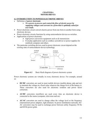


![Figure 6.21 Variable torque control
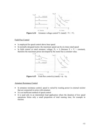
STATOR VOLTAGE CONTROL
• By reducing stator voltage, speed of a high slip induction motor can be reduced by an
amount which is sufficient for the speed control of some fan and pump drives.
• While torque is proportional to voltage squared, current is proportional to voltage.
,
3 2 R2
τ= Ir
ωm s
3 V 2R 2,
=
ωm 2
R + R 2 + X + X '
[ ]
'
2
1 s
1 2
• Thus, as voltage is reduced to reduced speed, for the same current, motor develops
lower torque.
• This method is suitable for applications where torque demand reduces with speed.
• Variable voltage for small size motors, particularly for single phase, is sometimes
obtained using autotransformer.
• However, more common method is the use of ac voltage controllers.
137](https://image.slidesharecdn.com/chapter6-powerelectronicdevices-110625084255-phpapp01/85/Chapter-6-power-electronic-devices-16-320.jpg)


The document discusses various types of motor drives used in power electronics. It describes different power switches used in power electronic circuits like diodes, thyristors, TRIACs, IGBTs, and provides their characteristics. It also summarizes different methods of speed control for DC motors like armature voltage control, field flux control and armature resistance control. For AC induction motors, it discusses speed control methods like pole changing, stator voltage control, supply frequency control and rotor resistance control.