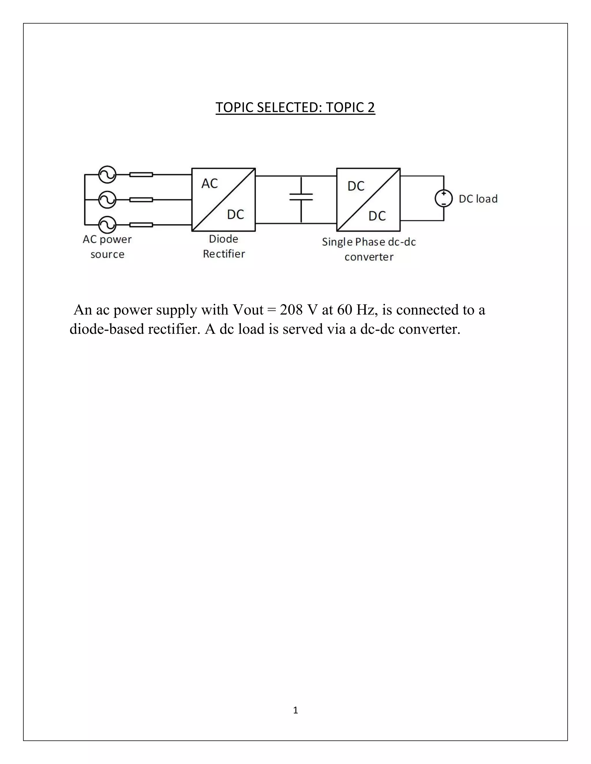
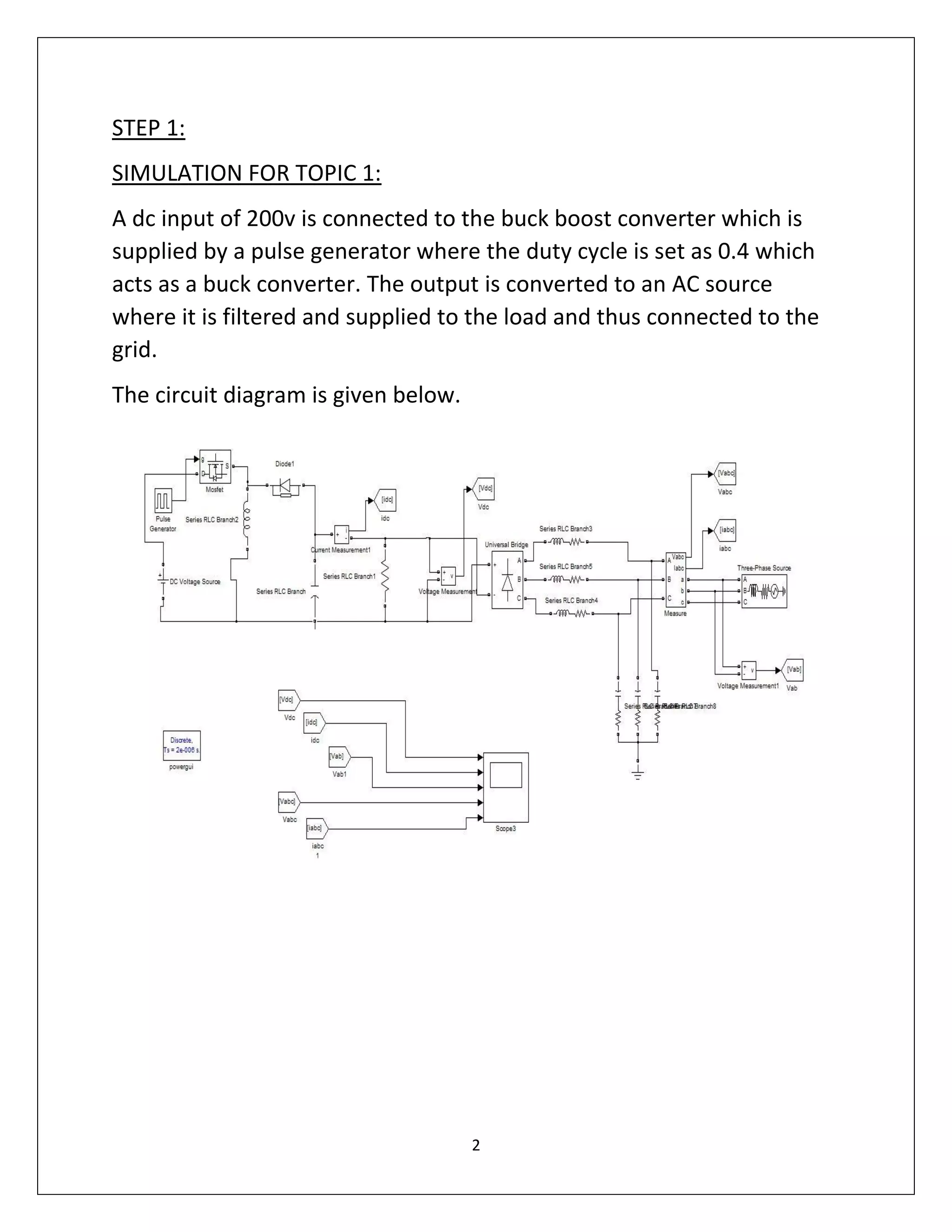
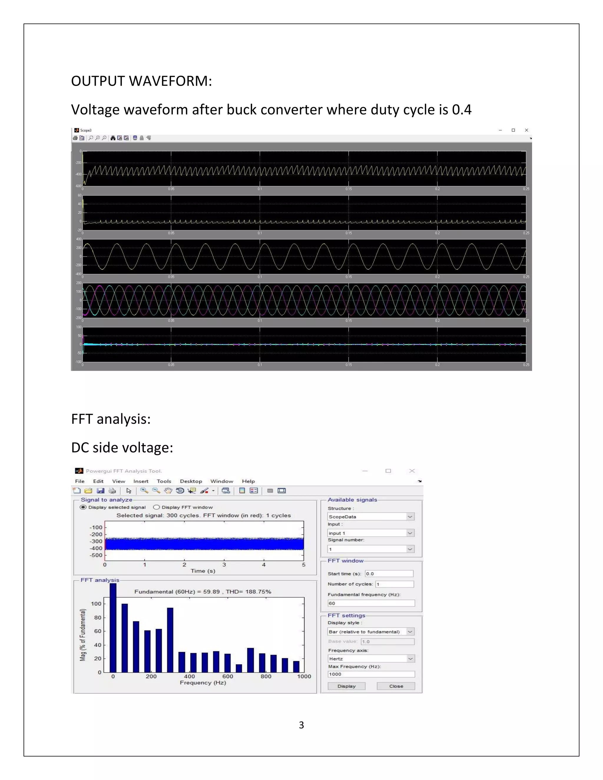
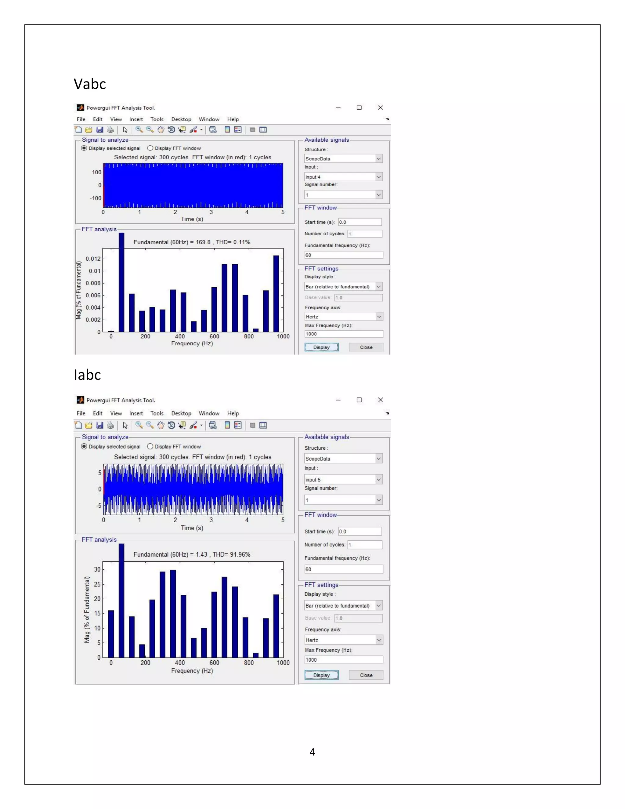
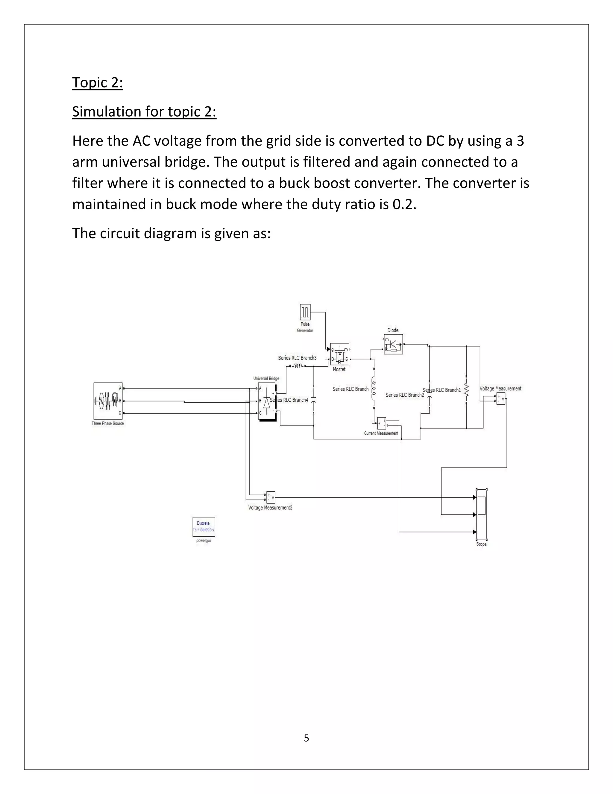
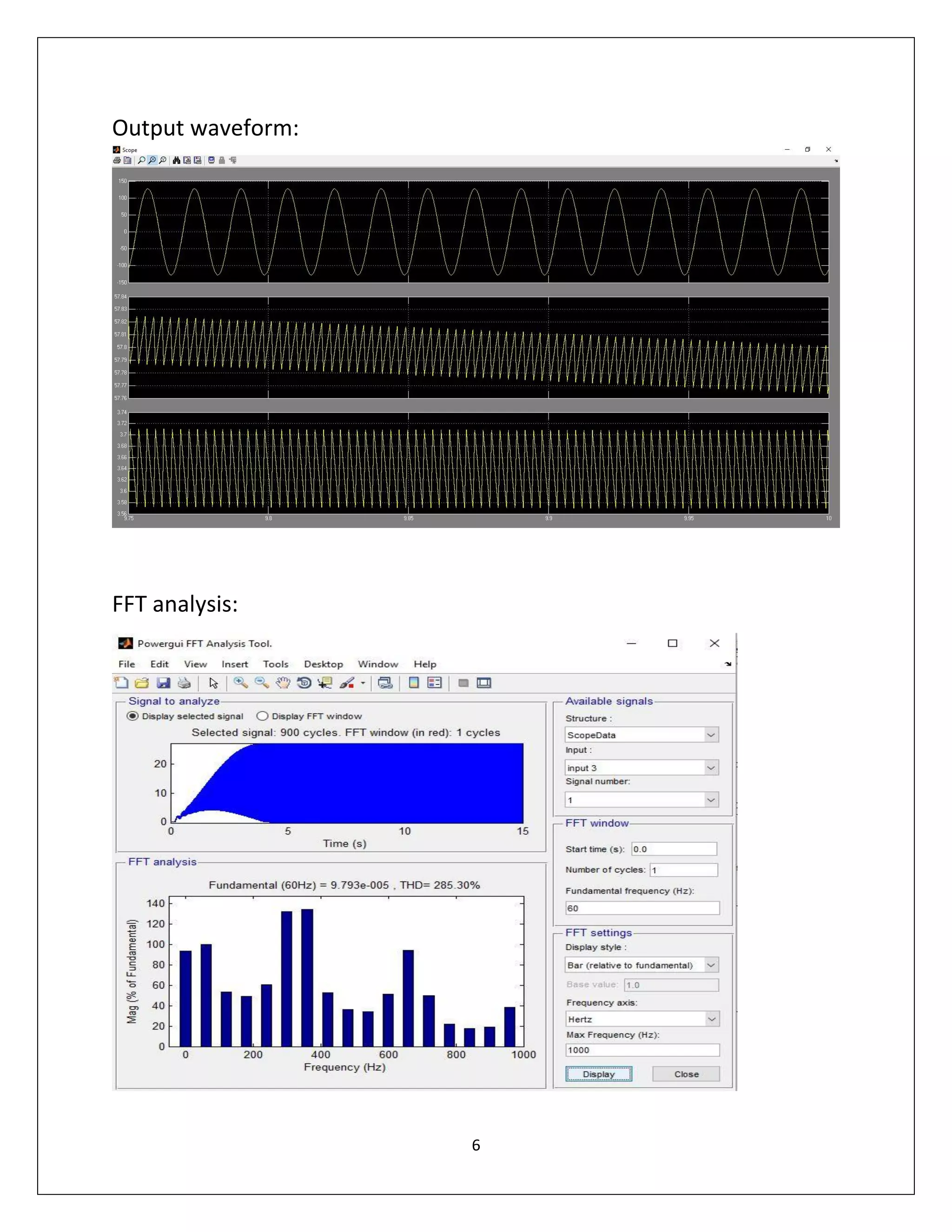
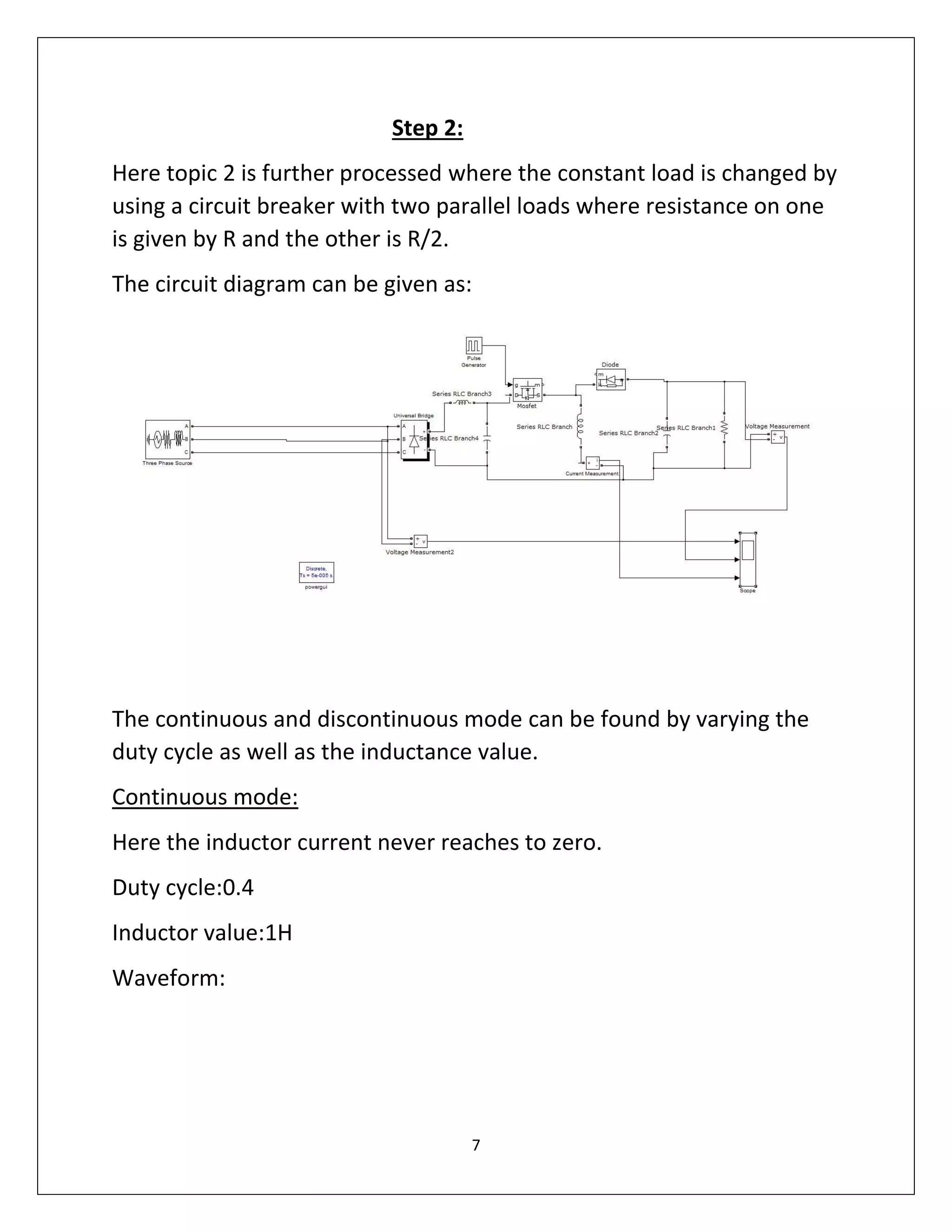
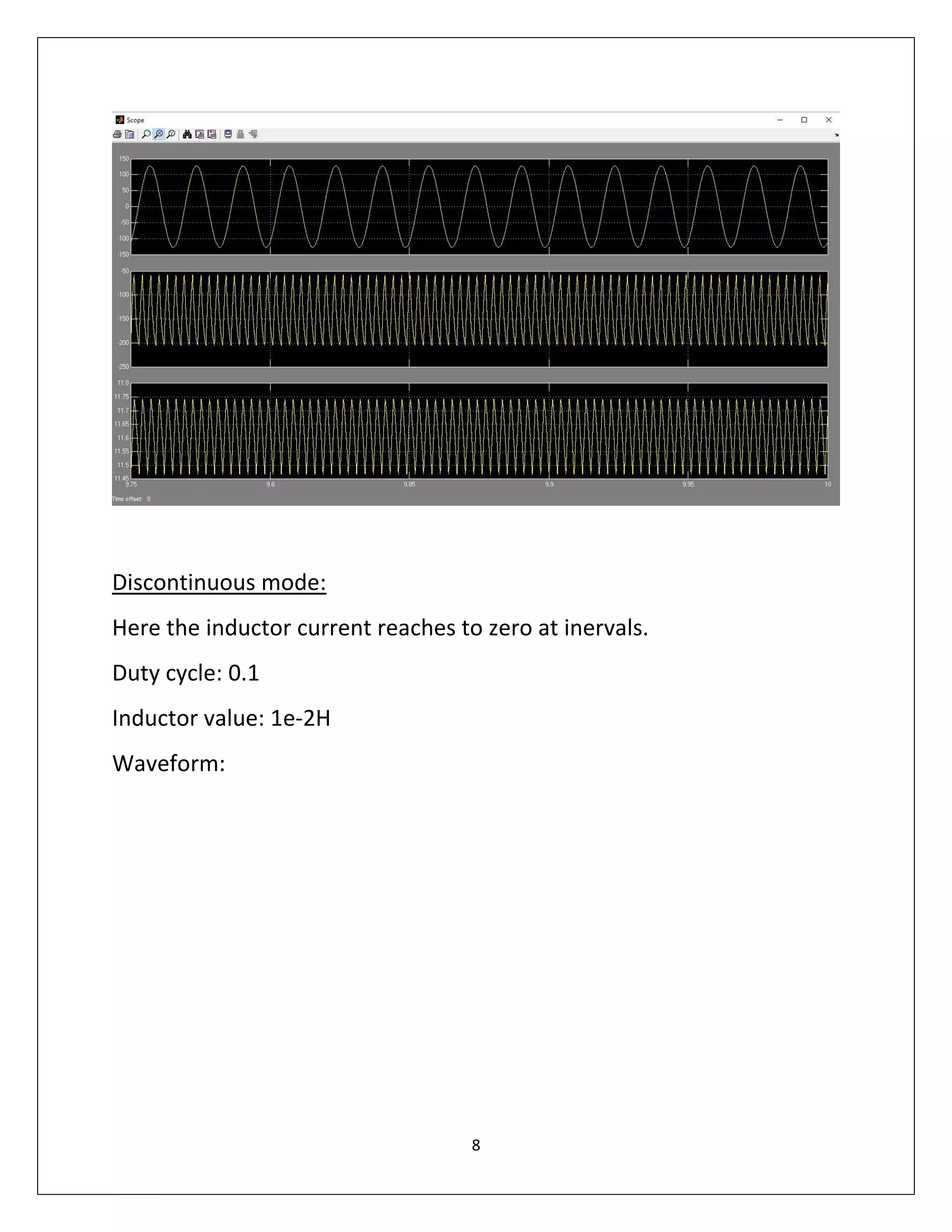
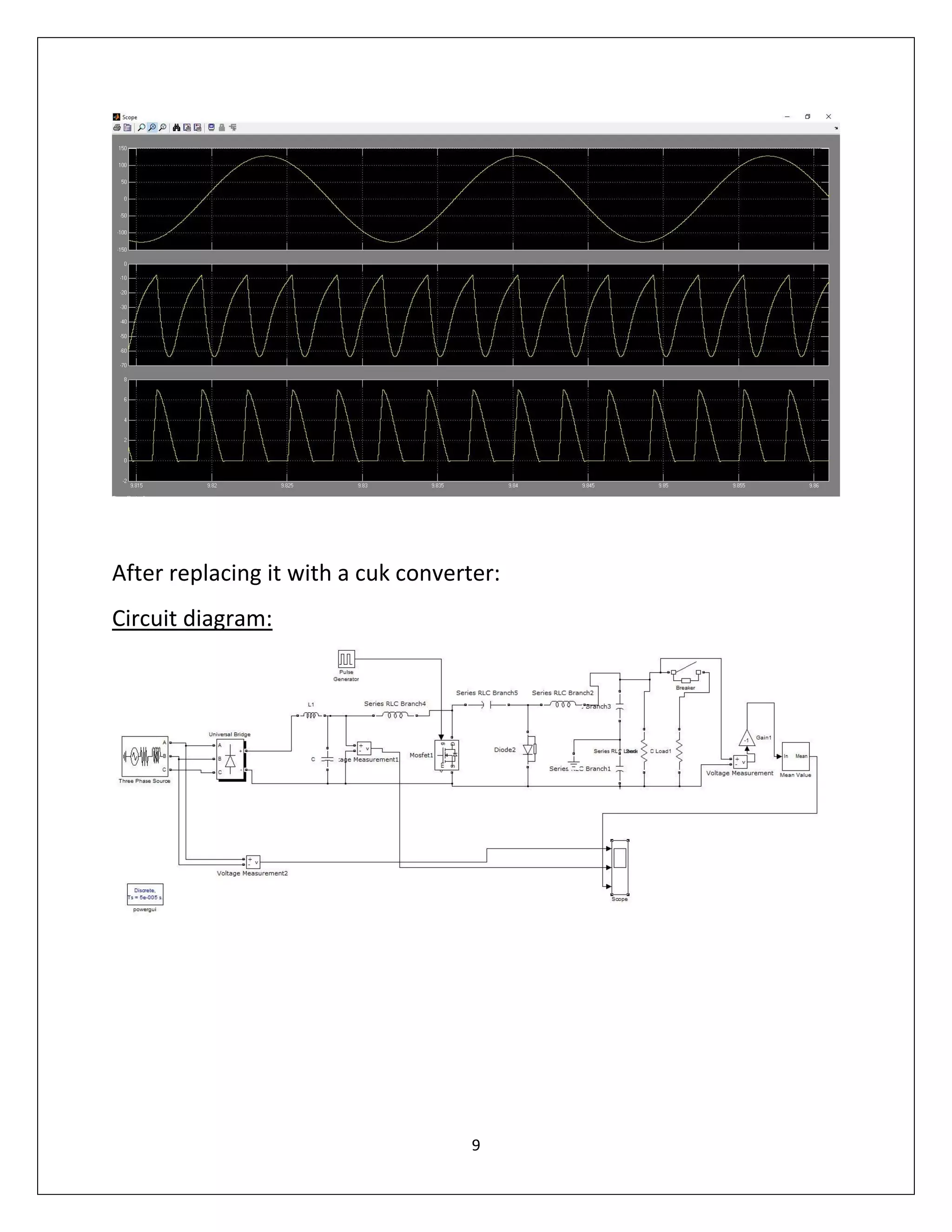
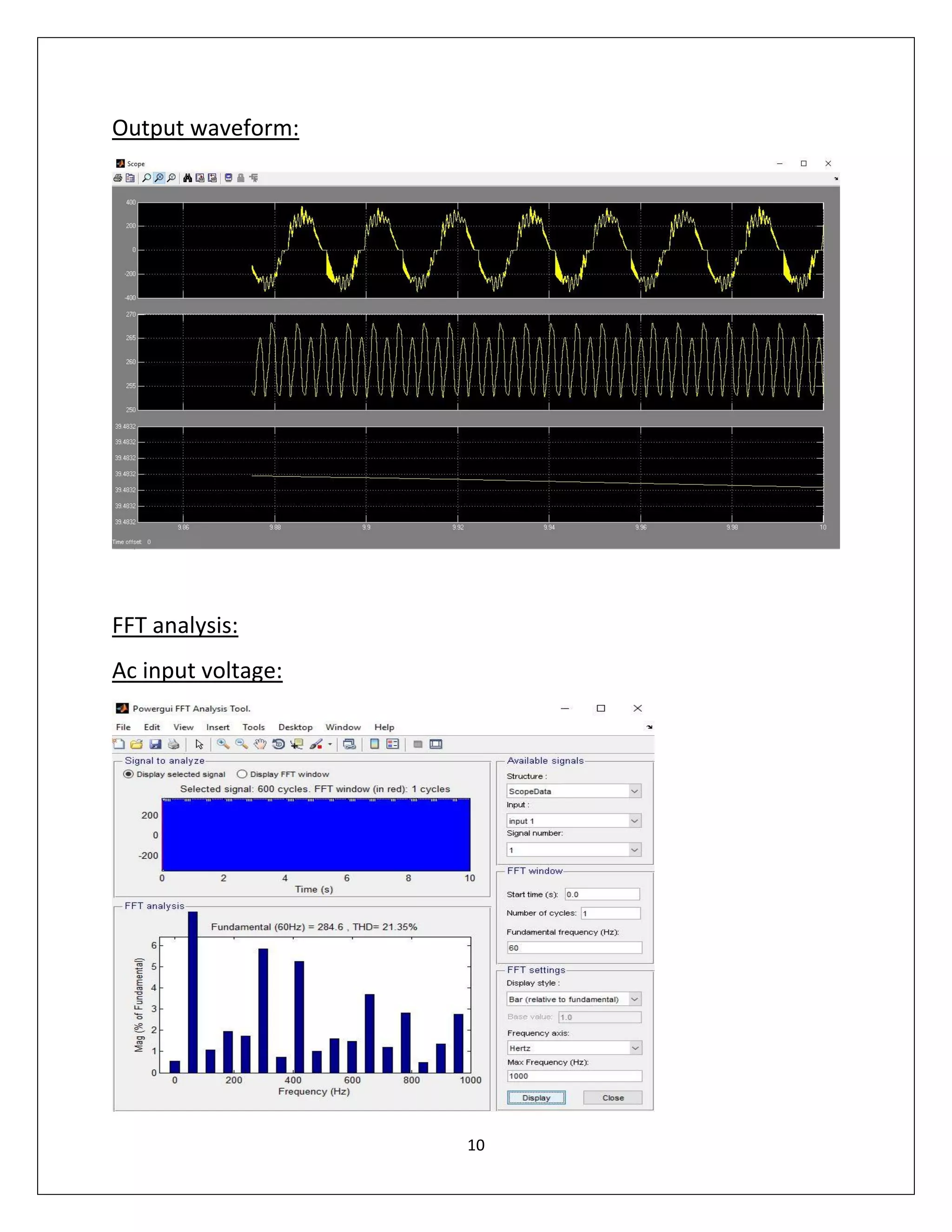
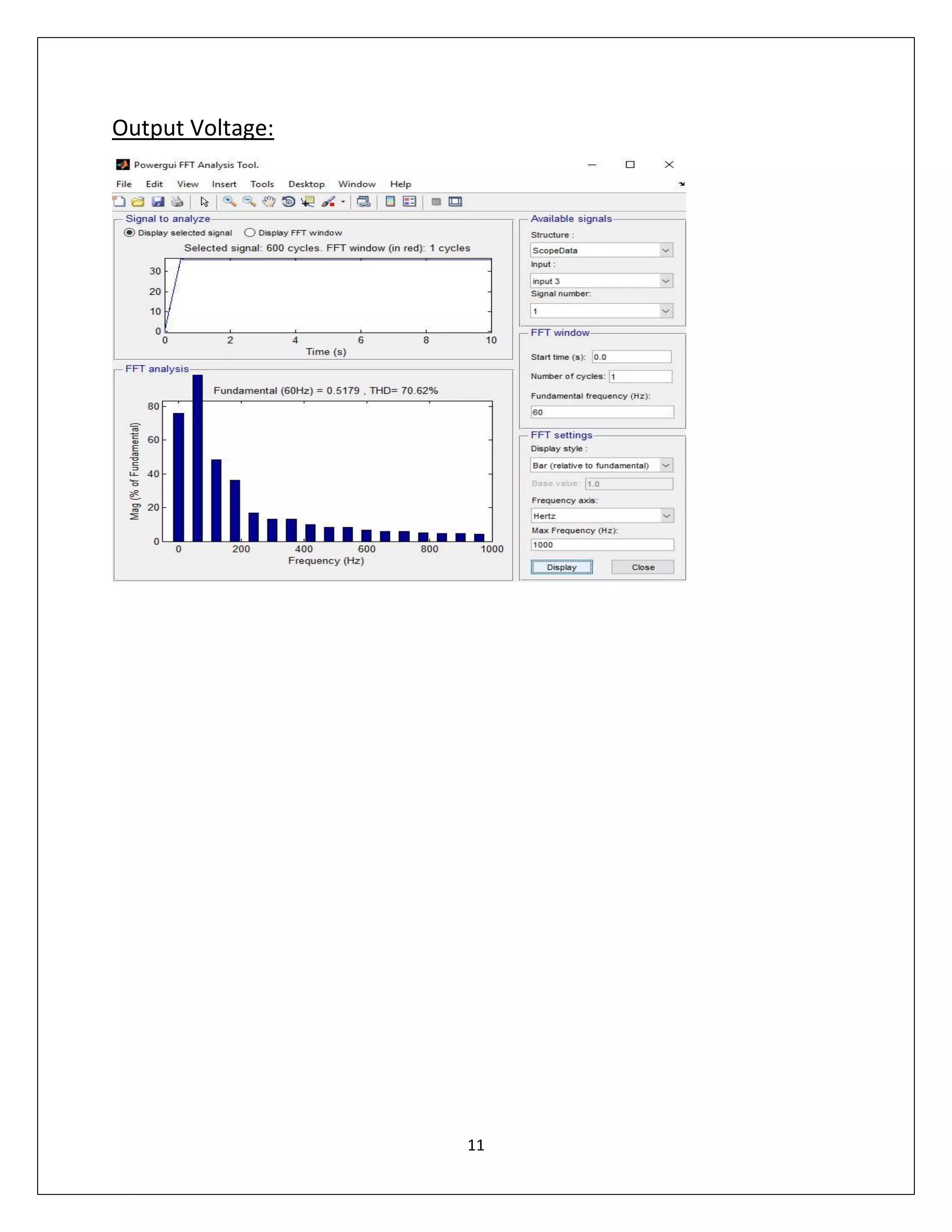
POWER ELECTRONICS
REPORT ON
COURSE PROJECT
2016
SUBMITTED BY:
EBBIN DANIEL
U80380223
1
TOPIC SELECTED: TOPIC 2
An ac power supply with Vout = 208 V at 60 Hz, is connected to a
diode-based rectifier. A dc load is served via a dc-dc converter.
2
STEP 1:
SIMULATION FOR TOPIC 1:
A dc input of 200v is connected to the buck boost converter which is
supplied by a pulse generator where the duty cycle is set as 0.4 which
acts as a buck converter. The output is converted to an AC source
where it is filtered and supplied to the load and thus connected to the
grid.
The circuit diagram is given below.
3
OUTPUT WAVEFORM:
Voltage waveform after buck converter where duty cycle is 0.4
FFT analysis:
DC side voltage:
4
Vabc
Iabc
5
Topic 2:
Simulation for topic 2:
Here the AC voltage from the grid side is converted to DC by using a 3
arm universal bridge. The output is filtered and again connected to a
filter where it is connected to a buck boost converter. The converter is
maintained in buck mode where the duty ratio is 0.2.
The circuit diagram is given as:
6
Output waveform:
FFT analysis:
7
Step 2:
Here topic 2 is further processed where the constant load is changed by
using a circuit breaker with two parallel loads where resistance on one
is given by R and the other is R/2.
The circuit diagram can be given as:
The continuous and discontinuous mode can be found by varying the
duty cycle as well as the inductance value.
Continuous mode:
Here the inductor current never reaches to zero.
Duty cycle:0.4
Inductor value:1H
Waveform:
8
Discontinuous mode:
Here the inductor current reaches to zero at inervals.
Duty cycle: 0.1
Inductor value: 1e-2H
Waveform:
9
After replacing it with a cuk converter:
Circuit diagram:
10
Output waveform:
FFT analysis:
Ac input voltage:
11
Output Voltage:

POWER ELECTRONICS

  • 1.
    POWER ELECTRONICS REPORT ON COURSEPROJECT 2016 SUBMITTED BY: EBBIN DANIEL U80380223
  • 2.
    1 TOPIC SELECTED: TOPIC2 An ac power supply with Vout = 208 V at 60 Hz, is connected to a diode-based rectifier. A dc load is served via a dc-dc converter.
  • 3.
    2 STEP 1: SIMULATION FORTOPIC 1: A dc input of 200v is connected to the buck boost converter which is supplied by a pulse generator where the duty cycle is set as 0.4 which acts as a buck converter. The output is converted to an AC source where it is filtered and supplied to the load and thus connected to the grid. The circuit diagram is given below.
  • 4.
    3 OUTPUT WAVEFORM: Voltage waveformafter buck converter where duty cycle is 0.4 FFT analysis: DC side voltage:
  • 5.
  • 6.
    5 Topic 2: Simulation fortopic 2: Here the AC voltage from the grid side is converted to DC by using a 3 arm universal bridge. The output is filtered and again connected to a filter where it is connected to a buck boost converter. The converter is maintained in buck mode where the duty ratio is 0.2. The circuit diagram is given as:
  • 7.
  • 8.
    7 Step 2: Here topic2 is further processed where the constant load is changed by using a circuit breaker with two parallel loads where resistance on one is given by R and the other is R/2. The circuit diagram can be given as: The continuous and discontinuous mode can be found by varying the duty cycle as well as the inductance value. Continuous mode: Here the inductor current never reaches to zero. Duty cycle:0.4 Inductor value:1H Waveform:
  • 9.
    8 Discontinuous mode: Here theinductor current reaches to zero at inervals. Duty cycle: 0.1 Inductor value: 1e-2H Waveform:
  • 10.
    9 After replacing itwith a cuk converter: Circuit diagram:
  • 11.
  • 12.