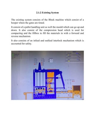
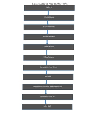
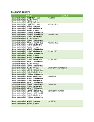
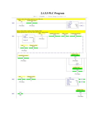
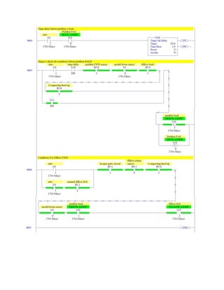
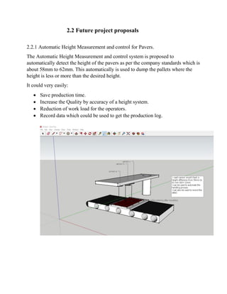
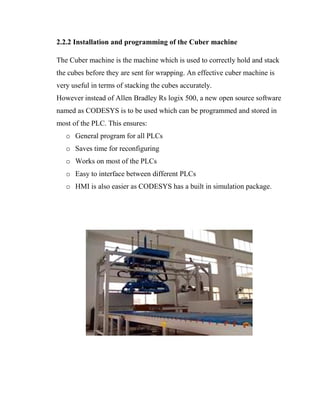
2016
Submitted by:
Ebbin Daniel
(Electrical Operations Intern)
USF ID : U80380223
(Summer 2016)
PROJECT REPORT
CONTENTS
PROJECT DESCRIPTION
2.1 Addition of Pushbar Mechanism
2.1.1 Introduction
2.1.2 Existing System
2.1.3 Proximity Sensors Used
2.1.3.1 Capacitive
2.1.3.2 Inductive
2.1.4 Industrial Lasers
2.1.4.1 Distance measuring lasers
2.1.5 PLC Programming
2.1.5.1 PLC used
2.1.5.2 Grafcet logic
2.1.5.3 Actions & Transitions
2.1.5.4 Input and outputs
2.1.5.5 PLC Program
2.2 Future project proposals
2.2.1 Automatic Height Measurement and control for
Pavers.
2.2.2 Installation and programming of the Cuber
machine
2.1 Addition of the Pushbar Mechanism
2.1.1 Introduction
Now-a-days, the major challenge that’s being faced by the concrete
industry is the cleaning of concrete handling equipment. Concrete consists
of aggregates, which harden with time, and the transportation of concrete
mixture within the plant is a significant problem. This will not only
increase the overall maintenance cost, but will lead to loss of raw
materials, affect the rate of production, and reduce the lifetime of concrete
handling equipment.
The present study focuses on the design and implementation of an
adaptive cleaning mechanism in the concrete industry and its importance
in achieving efficient cleaning, which is tested to verify its performance
in the Paver production plant. The goal of this study is to provide practical
evidence about the importance of adaptive cleaning mechanisms for
industrial applications.
This is achieved by addition of a pushbar mechanism which is turned on
when the Fill box is in rest position.
2.1.2 Existing System
The existing system consists of the Block machine which consist of a
hooper where the gates are timed.
It consist of a pallet handling unit as well the mould which can go up and
down. It also consist of the compression head which is used for
compacting and the fillbox to fill the materials in with a forward and
reverse mechanism.
It also consists of an infeed and outfeed interlock mechanism which is
accounted for safety.
2.1.3 Proximity Sensors Used
2.1.3.1 Capacitive
Capacitive proximity sensors are similar to inductive proximity sensors. The main
difference between the two types is that capacitive proximity sensors produce an
electrostatic field instead of an electromagnetic field. Capacitive proximity switches
will sense metal as well as nonmetallic materials such as paper, glass, liquids, and
cloth.
The sensing surface of a capacitive sensor is formed by two concentrically shaped
metal electrodes of an unwound capacitor. When an object nears the sensing
surface it enters the electrostatic field of the electrodes and changes the capacitance
in an oscillator circuit. As a result, the oscillator begins oscillating.
The trigger circuit reads the oscillator’s amplitude and when it reaches a specific
level the output state of the sensor changes. As the target moves away from the
sensor the oscillator’s amplitude decreases, switching the sensor output back to its
original state
Standard targets are specified for each capacitive sensor. The Dielectric Constant
standard target is usually defined as metal and/or water. Capacitive sensors depend
on the dielectric constant of the target. The larger the dielectric number of a
material the easier it is to detect.
2.1.3.2 Inductive
For non-contact detection of metallic targets at ranges generally under 50mm (2
inches).
Inductive proximity sensors emit an alternating electro-magnetic sensing field.
When a metal target enters the sensing field, eddy currents are induced in the
target, reducing the signal amplitude and triggering a change of state at the sensor
output.
Advantages of inductive proximity sensors include:
 Ignores water, oil, dirt, and non-metallic particles
 Insensitive to target color or target surface finish
 Short-circuit resistant
 Withstands high shock and vibration environments
2.1.4 Industrial Lasers
2.1.4.1 Distance measuring lasers
Some applications require not only knowing if the object is present or not but
exactly where the object is while providing a continuous or dynamic value
representative of the objects location. For instance, if robots are stacking a product:
 Is the stack at the correct height?
 How many additional pieces can be placed on the stack?
 How large is the coil or roll diameter of a product?
 How high is the level or how much further can the product move before it is
in position?
Distance sensors can provide this dynamic information and in some cases provide
a digital output for alarms.
These sensors are normally based on diffuse sensing technology. In some cases
retroreflective technology is used for extremely long sensing distances. As with
diffuse sensors, there is only one device to mount and wire.
However, due to the technology required for the higher resolutions, lensing,
electronics, and outputs, these devices are typically much more expensive than a
discrete diffuse sensor.
Similar to a diffuse sensor, the distance sensor emits a pulsed light that strikes an
object and a certain amount of light is reflected back to the sensor’s receiver. The
sensor then generates an analog output signal that is proportional to the distance to
the target. The technology that is utilized within the sensor to determine the
distance is either Time of Flight or Triangulation.
2.1.5 PLC Programming
2.1.5.1 PLC used
Allen Bradley SLC 500 series
Features
 Ladder-logic and structured-text programming
 Advanced instruction set including file handling, sequencer, diagnostic, shift
register, immediate I/O, and program control instructions
 Built-in RS-232/422/423 communication port
 DeviceNet and ControlNet I/O on selected processors
 One or more on-board ports that can be configured for either Data Highway Plus™
(DH+) or Universal Remote I/O
 Universal Remote I/O ports can be configured as an I/O scanner port or an I/O
adapter port
 Ethernet PLC-5® controllers and the Ethernet interface module (1785-ENET)
provide built-in web services
 Backup options for increased fault tolerance through the ControlNet™ Hot Backup
module or the PLC-5 Backup Communication module
SLC 500 Controller Comparison
Pallet IN
Mould Down
Feedbox Forward
Feedbox retract
PushBar Forward
Pushbar retract
Compacting head Down
Vibration
Demoulding ( mould UP, compacting head partially UP)
Compacting head up
Pallet out
Hooper gate open
4
0
1
2
8
3
5
6
10
11
7
9
Pallet IN. mould down.head up.fillbox back.pushbar back
mould down.head up.fillbox back.pushbar back
mould down.head up.fillbox back.pushbar FWD
mould down.head up.fillbox back.pushbar back
mould down.head up.fillbox FWD.pushbar back.hooper gates closed
mould down.head up.fillbox back.pushbar back.hooper gates opened
mould down.head up.fillbox back
mould down.head down.fillbox back.pushbar back
mould UP.head UP.fillbox back.pushbar back
mould up.head up.fillbox back.pushbar back
2.1.5.2 Grafcet – block machine
Pallet IN
Mould DOWN
Pushbar extends
Pallet OUT
Compacting head up
Compacting Head down
Pushbar Retracts
Fillbox Extends
Vibration
Fillbox Retracts
Demoulding (mould up , head partially up)
2.1.5.4 INPUTS & OUTPUTS
INPUTS OUTPUT
Sensor that checks if PALLET OUT = true
Sensor that checks if HEAD is UP=true
Sensor that checks if MOULD is UP =true
PALLET IN
Sensor that checks if PALLET is IN = true
Sensor that checks if MOULD is UP =true
Sensor that checks if FILLBOX is BACK= true
Sensor that checks if HEAD is UP =true
Sensor that checks if PUSHBAR is BACK= true
MOULD DOWN
Sensor that checks if PUSHBAR is BACK= true
Sensor that checks if FILLBOX is BACK= true
Sensor that checks if HEAD is UP =true
Sensor that checks if MOULD is DOWN =true
PUSHBAR FWD
Sensor that checks if PUSHBAR is FWD= true
Sensor that checks if FILLBOX is BACK= true
Sensor that checks if HEAD is UP =true
Sensor that checks if MOULD is DOWN =true
PUSHBAR BACK
Sensor that checks if FILLBOX is BACK= true
Sensor that checks if PUSHBAR is BACK= true
Sensor that checks if HEAD is UP =true
Sensor that checks if MOULD is DOWN =true
FILLBOX FWD
Sensor that checks if FILLBOX is FWD= true
Sensor that checks if PUSHBAR is BACK= true
Sensor that checks if HEAD is UP =true
Sensor that checks if MOULD is DOWN =true
FILLBOX BACK
Sensor that checks if HEAD is UP =true
Sensor that checks if MOULD is DOWN =true
Sensor that checks if FILLBOX is BACK= true
Sensor that checks if PUSHBAR is BACK= true
COMPACTING HEAD DOWN
Sensor that checks if HEAD is DOWN= true
Sensor that checks if MOULD is DOWN =true
Sensor that checks if FILLBOX is BACK= true
Sensor that checks if PUSHBAR is BACK= true
VIBRATION
Sensor that checks if MOULD is DOWN =true
Sensor that checks if FILLBOX is BACK= true
Sensor that checks if PUSHBAR is BACK= true
MOULD UP
Sensor that checks if MOULD is DOWN =true
Sensor that checks if HEAD is DOWN =FALSE
Sensor that checks if FILLBOX is BACK= true
Sensor that checks if PUSHBAR is BACK= true
COMPACTING HEAD UP
Sensor that checks if MOULD is UP =true
Sensor that checks if HEAD is UP =true
PALLET OUT
2.1.5.5 PLC Program
2.2 Future project proposals
2.2.1 Automatic Height Measurement and control for Pavers.
The Automatic Height Measurement and control system is proposed to
automatically detect the height of the pavers as per the company standards which is
about 58mm to 62mm. This automatically is used to dump the pallets where the
height is less or more than the desired height.
It could very easily:
 Save production time.
 Increase the Quality by accuracy of a height system.
 Reduction of work load for the operators.
 Record data which could be used to get the production log.
2.2.2 Installation and programming of the Cuber machine
The Cuber machine is the machine which is used to correctly hold and stack
the cubes before they are sent for wrapping. An effective cuber machine is
very useful in terms of stacking the cubes accurately.
However instead of Allen Bradley Rs logix 500, a new open source software
named as CODESYS is to be used which can be programmed and stored in
most of the PLC. This ensures:
o General program for all PLCs
o Saves time for reconfiguring
o Works on most of the PLCs
o Easy to interface between different PLCs
o HMI is also easier as CODESYS has a built in simulation package.

TREMRON_PROJECT_summer

  • 1.
    2016 Submitted by: Ebbin Daniel (ElectricalOperations Intern) USF ID : U80380223 (Summer 2016) PROJECT REPORT
  • 2.
    CONTENTS PROJECT DESCRIPTION 2.1 Additionof Pushbar Mechanism 2.1.1 Introduction 2.1.2 Existing System 2.1.3 Proximity Sensors Used 2.1.3.1 Capacitive 2.1.3.2 Inductive 2.1.4 Industrial Lasers 2.1.4.1 Distance measuring lasers 2.1.5 PLC Programming 2.1.5.1 PLC used 2.1.5.2 Grafcet logic 2.1.5.3 Actions & Transitions 2.1.5.4 Input and outputs 2.1.5.5 PLC Program 2.2 Future project proposals 2.2.1 Automatic Height Measurement and control for Pavers. 2.2.2 Installation and programming of the Cuber machine
  • 3.
    2.1 Addition ofthe Pushbar Mechanism 2.1.1 Introduction Now-a-days, the major challenge that’s being faced by the concrete industry is the cleaning of concrete handling equipment. Concrete consists of aggregates, which harden with time, and the transportation of concrete mixture within the plant is a significant problem. This will not only increase the overall maintenance cost, but will lead to loss of raw materials, affect the rate of production, and reduce the lifetime of concrete handling equipment. The present study focuses on the design and implementation of an adaptive cleaning mechanism in the concrete industry and its importance in achieving efficient cleaning, which is tested to verify its performance in the Paver production plant. The goal of this study is to provide practical evidence about the importance of adaptive cleaning mechanisms for industrial applications. This is achieved by addition of a pushbar mechanism which is turned on when the Fill box is in rest position.
  • 4.
    2.1.2 Existing System Theexisting system consists of the Block machine which consist of a hooper where the gates are timed. It consist of a pallet handling unit as well the mould which can go up and down. It also consist of the compression head which is used for compacting and the fillbox to fill the materials in with a forward and reverse mechanism. It also consists of an infeed and outfeed interlock mechanism which is accounted for safety.
  • 5.
    2.1.3 Proximity SensorsUsed 2.1.3.1 Capacitive Capacitive proximity sensors are similar to inductive proximity sensors. The main difference between the two types is that capacitive proximity sensors produce an electrostatic field instead of an electromagnetic field. Capacitive proximity switches will sense metal as well as nonmetallic materials such as paper, glass, liquids, and cloth. The sensing surface of a capacitive sensor is formed by two concentrically shaped metal electrodes of an unwound capacitor. When an object nears the sensing surface it enters the electrostatic field of the electrodes and changes the capacitance in an oscillator circuit. As a result, the oscillator begins oscillating. The trigger circuit reads the oscillator’s amplitude and when it reaches a specific level the output state of the sensor changes. As the target moves away from the sensor the oscillator’s amplitude decreases, switching the sensor output back to its original state
  • 6.
    Standard targets arespecified for each capacitive sensor. The Dielectric Constant standard target is usually defined as metal and/or water. Capacitive sensors depend on the dielectric constant of the target. The larger the dielectric number of a material the easier it is to detect.
  • 7.
    2.1.3.2 Inductive For non-contactdetection of metallic targets at ranges generally under 50mm (2 inches). Inductive proximity sensors emit an alternating electro-magnetic sensing field. When a metal target enters the sensing field, eddy currents are induced in the target, reducing the signal amplitude and triggering a change of state at the sensor output. Advantages of inductive proximity sensors include:  Ignores water, oil, dirt, and non-metallic particles  Insensitive to target color or target surface finish  Short-circuit resistant  Withstands high shock and vibration environments
  • 8.
    2.1.4 Industrial Lasers 2.1.4.1Distance measuring lasers Some applications require not only knowing if the object is present or not but exactly where the object is while providing a continuous or dynamic value representative of the objects location. For instance, if robots are stacking a product:  Is the stack at the correct height?  How many additional pieces can be placed on the stack?  How large is the coil or roll diameter of a product?  How high is the level or how much further can the product move before it is in position? Distance sensors can provide this dynamic information and in some cases provide a digital output for alarms. These sensors are normally based on diffuse sensing technology. In some cases retroreflective technology is used for extremely long sensing distances. As with diffuse sensors, there is only one device to mount and wire.
  • 9.
    However, due tothe technology required for the higher resolutions, lensing, electronics, and outputs, these devices are typically much more expensive than a discrete diffuse sensor. Similar to a diffuse sensor, the distance sensor emits a pulsed light that strikes an object and a certain amount of light is reflected back to the sensor’s receiver. The sensor then generates an analog output signal that is proportional to the distance to the target. The technology that is utilized within the sensor to determine the distance is either Time of Flight or Triangulation.
  • 10.
    2.1.5 PLC Programming 2.1.5.1PLC used Allen Bradley SLC 500 series Features  Ladder-logic and structured-text programming  Advanced instruction set including file handling, sequencer, diagnostic, shift register, immediate I/O, and program control instructions  Built-in RS-232/422/423 communication port  DeviceNet and ControlNet I/O on selected processors  One or more on-board ports that can be configured for either Data Highway Plus™ (DH+) or Universal Remote I/O  Universal Remote I/O ports can be configured as an I/O scanner port or an I/O adapter port  Ethernet PLC-5® controllers and the Ethernet interface module (1785-ENET) provide built-in web services  Backup options for increased fault tolerance through the ControlNet™ Hot Backup module or the PLC-5 Backup Communication module
  • 11.
  • 12.
    Pallet IN Mould Down FeedboxForward Feedbox retract PushBar Forward Pushbar retract Compacting head Down Vibration Demoulding ( mould UP, compacting head partially UP) Compacting head up Pallet out Hooper gate open 4 0 1 2 8 3 5 6 10 11 7 9 Pallet IN. mould down.head up.fillbox back.pushbar back mould down.head up.fillbox back.pushbar back mould down.head up.fillbox back.pushbar FWD mould down.head up.fillbox back.pushbar back mould down.head up.fillbox FWD.pushbar back.hooper gates closed mould down.head up.fillbox back.pushbar back.hooper gates opened mould down.head up.fillbox back mould down.head down.fillbox back.pushbar back mould down.head down.fillbox back.pushbar back mould UP.head UP.fillbox back.pushbar back mould up.head up.fillbox back.pushbar back 2.1.5.2 Grafcet – block machine
  • 13.
    Pallet IN Mould DOWN Pushbarextends Pallet OUT Compacting head up Compacting Head down Pushbar Retracts Fillbox Extends Vibration Fillbox Retracts Demoulding (mould up , head partially up)
  • 14.
    2.1.5.4 INPUTS &OUTPUTS INPUTS OUTPUT Sensor that checks if PALLET OUT = true Sensor that checks if HEAD is UP=true Sensor that checks if MOULD is UP =true PALLET IN Sensor that checks if PALLET is IN = true Sensor that checks if MOULD is UP =true Sensor that checks if FILLBOX is BACK= true Sensor that checks if HEAD is UP =true Sensor that checks if PUSHBAR is BACK= true MOULD DOWN Sensor that checks if PUSHBAR is BACK= true Sensor that checks if FILLBOX is BACK= true Sensor that checks if HEAD is UP =true Sensor that checks if MOULD is DOWN =true PUSHBAR FWD Sensor that checks if PUSHBAR is FWD= true Sensor that checks if FILLBOX is BACK= true Sensor that checks if HEAD is UP =true Sensor that checks if MOULD is DOWN =true PUSHBAR BACK Sensor that checks if FILLBOX is BACK= true Sensor that checks if PUSHBAR is BACK= true Sensor that checks if HEAD is UP =true Sensor that checks if MOULD is DOWN =true FILLBOX FWD Sensor that checks if FILLBOX is FWD= true Sensor that checks if PUSHBAR is BACK= true Sensor that checks if HEAD is UP =true Sensor that checks if MOULD is DOWN =true FILLBOX BACK Sensor that checks if HEAD is UP =true Sensor that checks if MOULD is DOWN =true Sensor that checks if FILLBOX is BACK= true Sensor that checks if PUSHBAR is BACK= true COMPACTING HEAD DOWN Sensor that checks if HEAD is DOWN= true Sensor that checks if MOULD is DOWN =true Sensor that checks if FILLBOX is BACK= true Sensor that checks if PUSHBAR is BACK= true VIBRATION Sensor that checks if MOULD is DOWN =true Sensor that checks if FILLBOX is BACK= true Sensor that checks if PUSHBAR is BACK= true MOULD UP Sensor that checks if MOULD is DOWN =true Sensor that checks if HEAD is DOWN =FALSE Sensor that checks if FILLBOX is BACK= true Sensor that checks if PUSHBAR is BACK= true COMPACTING HEAD UP Sensor that checks if MOULD is UP =true Sensor that checks if HEAD is UP =true PALLET OUT
  • 15.
  • 17.
    2.2 Future projectproposals 2.2.1 Automatic Height Measurement and control for Pavers. The Automatic Height Measurement and control system is proposed to automatically detect the height of the pavers as per the company standards which is about 58mm to 62mm. This automatically is used to dump the pallets where the height is less or more than the desired height. It could very easily:  Save production time.  Increase the Quality by accuracy of a height system.  Reduction of work load for the operators.  Record data which could be used to get the production log.
  • 18.
    2.2.2 Installation andprogramming of the Cuber machine The Cuber machine is the machine which is used to correctly hold and stack the cubes before they are sent for wrapping. An effective cuber machine is very useful in terms of stacking the cubes accurately. However instead of Allen Bradley Rs logix 500, a new open source software named as CODESYS is to be used which can be programmed and stored in most of the PLC. This ensures: o General program for all PLCs o Saves time for reconfiguring o Works on most of the PLCs o Easy to interface between different PLCs o HMI is also easier as CODESYS has a built in simulation package.