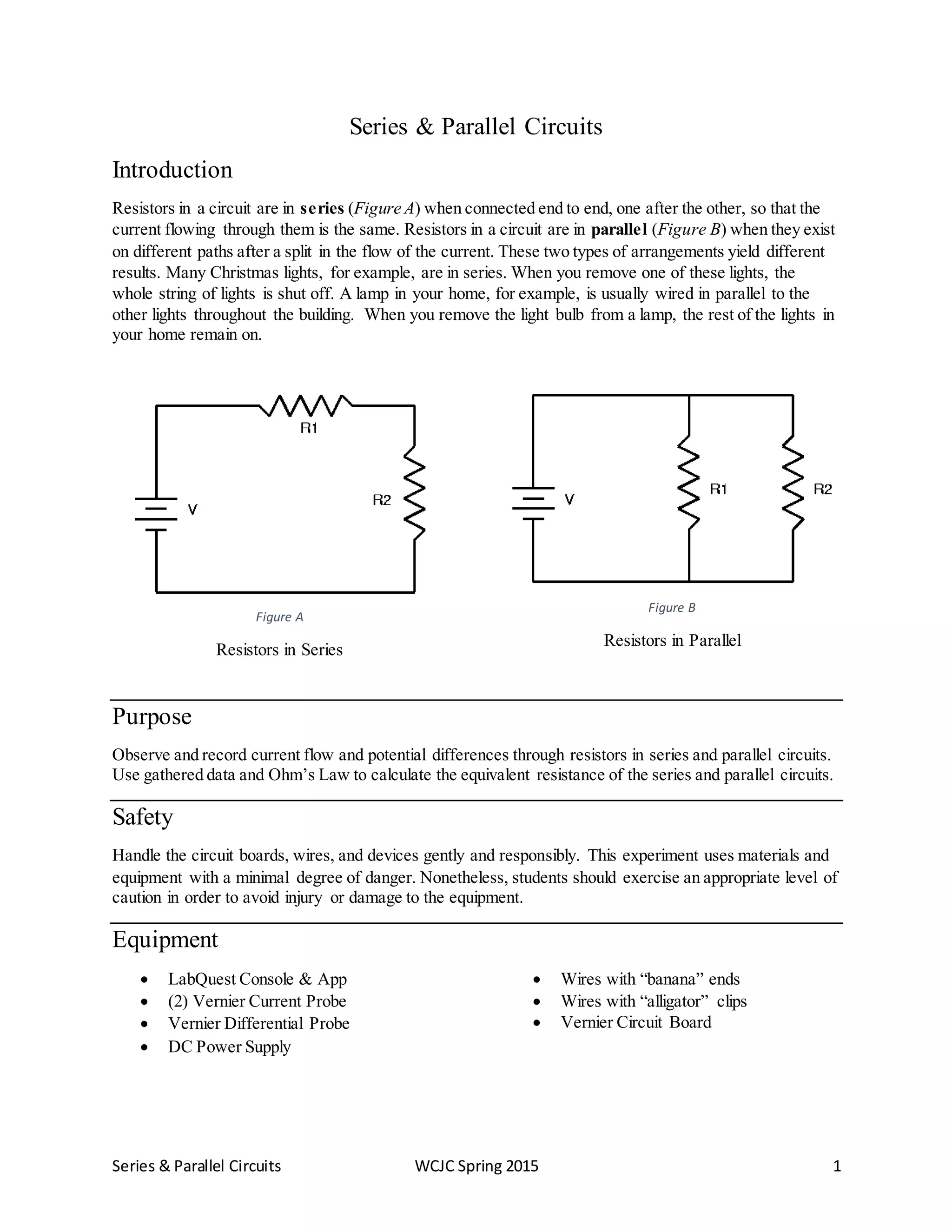
1. The document describes an experiment to measure and compare current and voltage in series and parallel circuits using resistors and circuit boards. Resistors in series experience the same current but their voltages add up to the total. Resistors in parallel experience the same voltage but their currents combine.
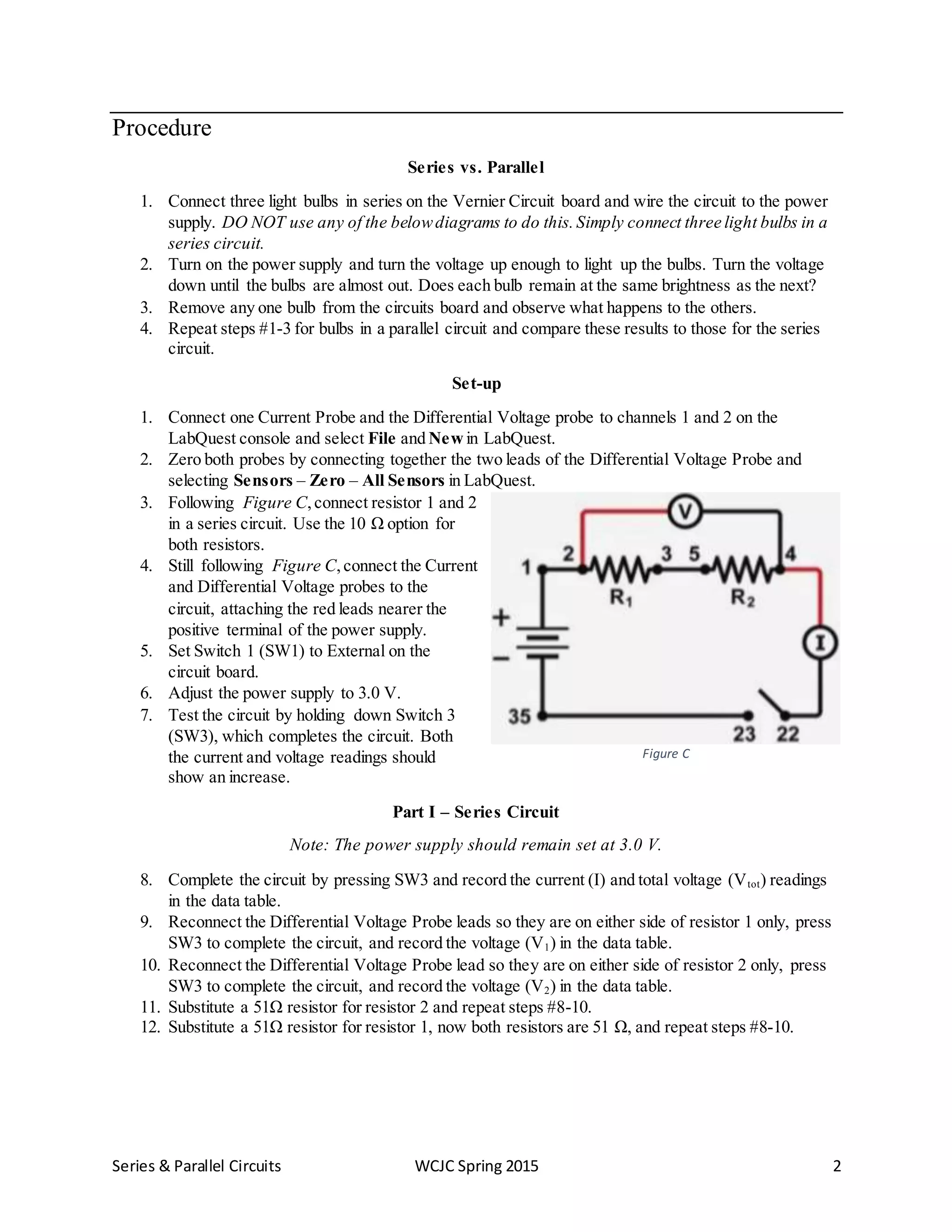
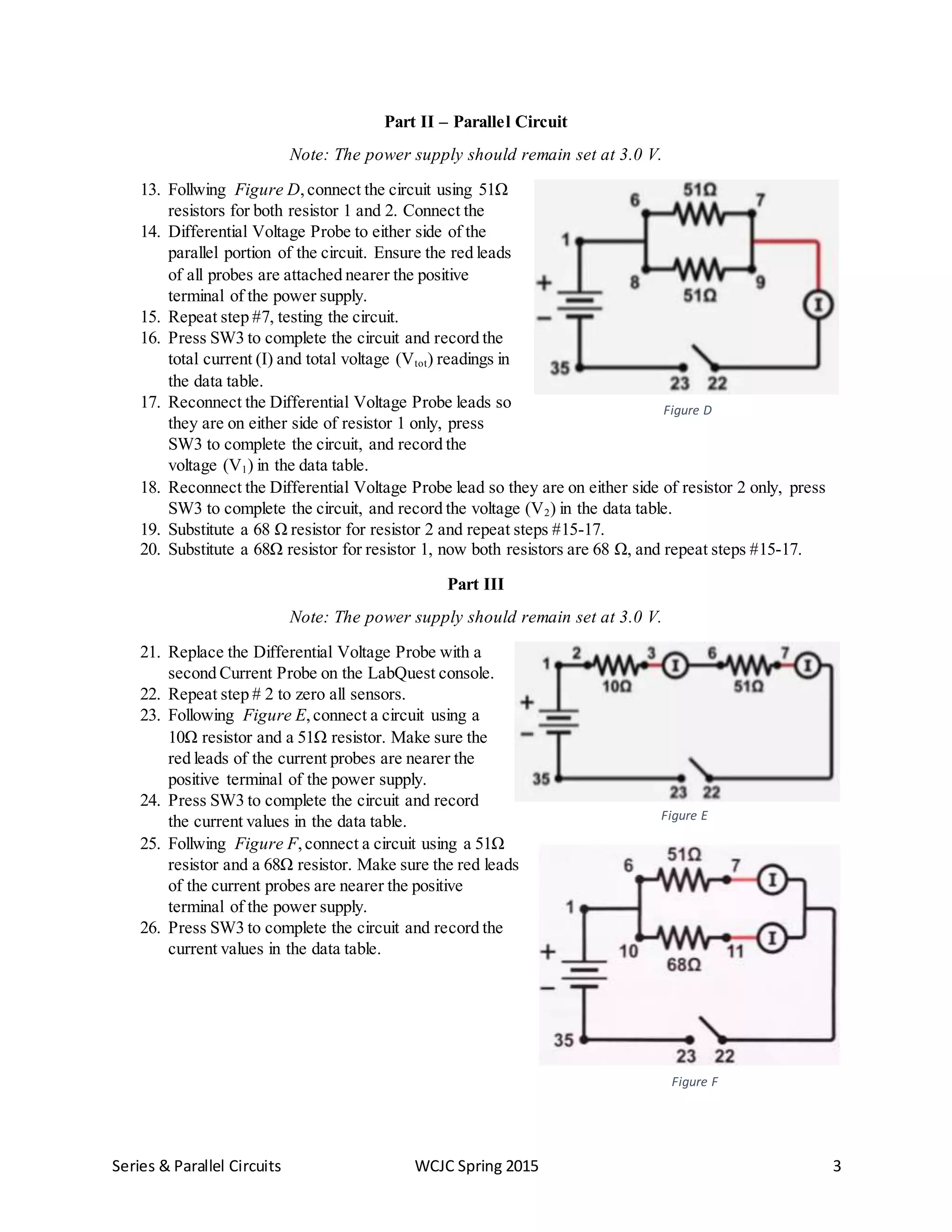
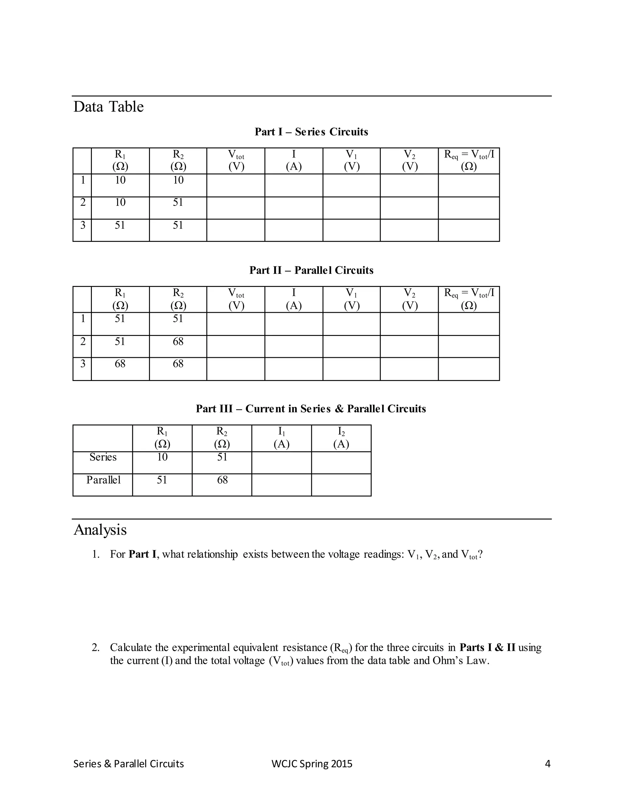
2. The experiment involves building series and parallel circuits with different resistor combinations and measuring current, voltage, and calculating equivalent resistance using Ohm's Law. Data is recorded and analyzed to determine relationships between voltages in series and parallel circuits.