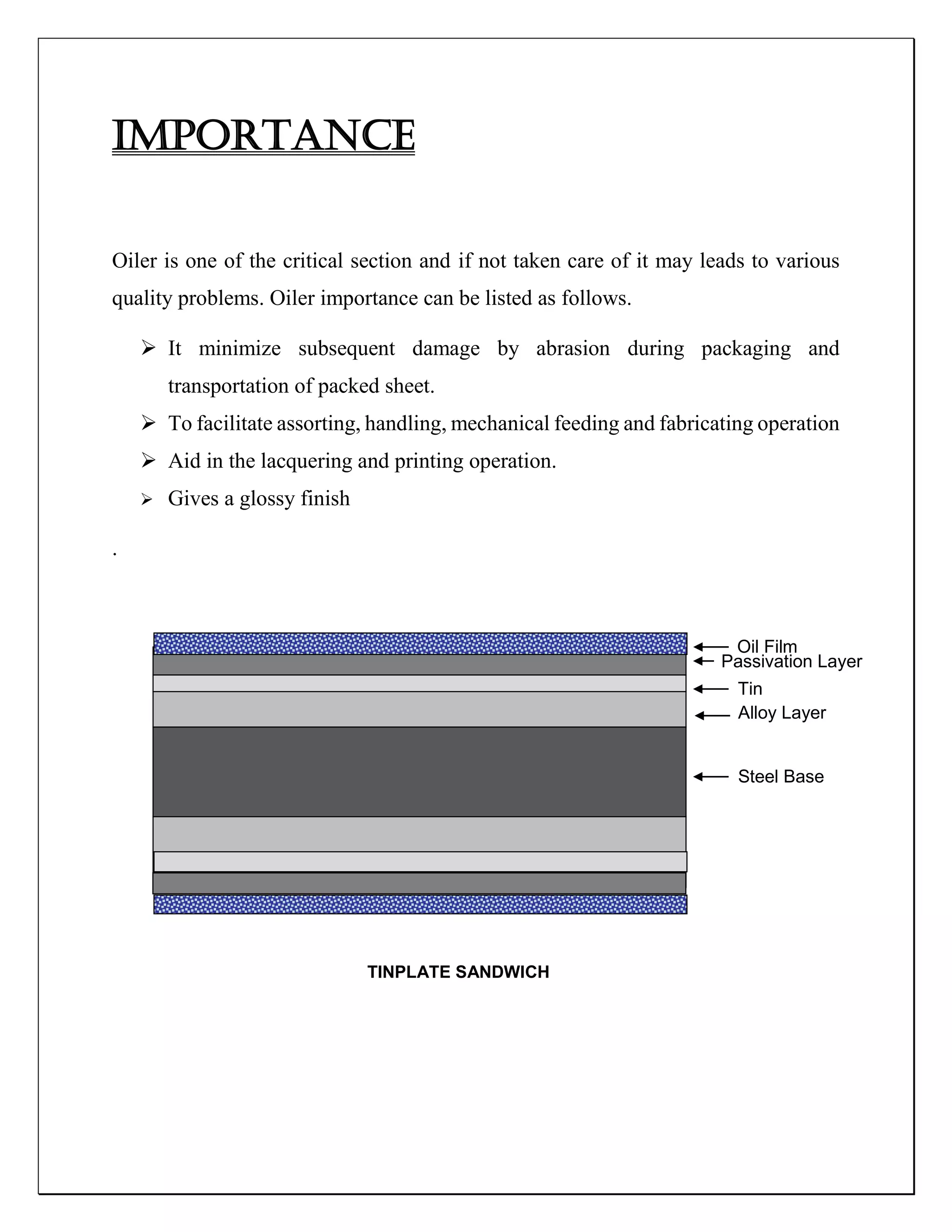
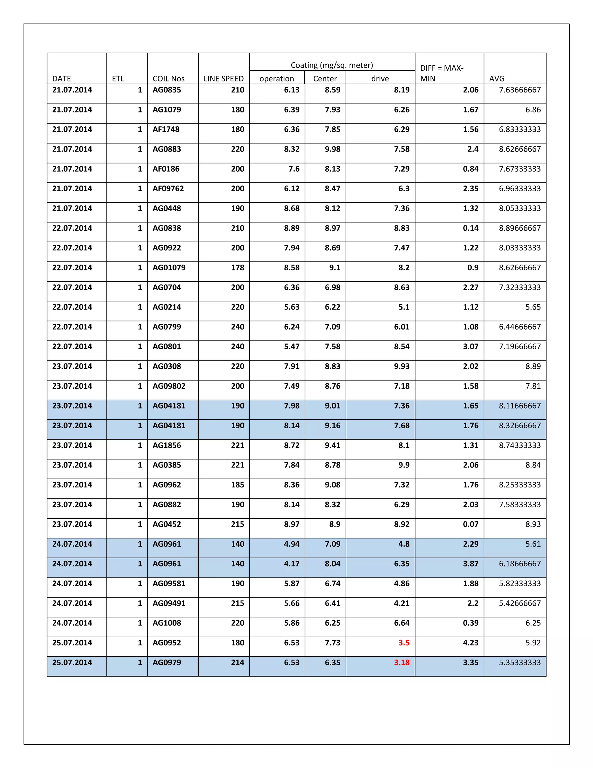
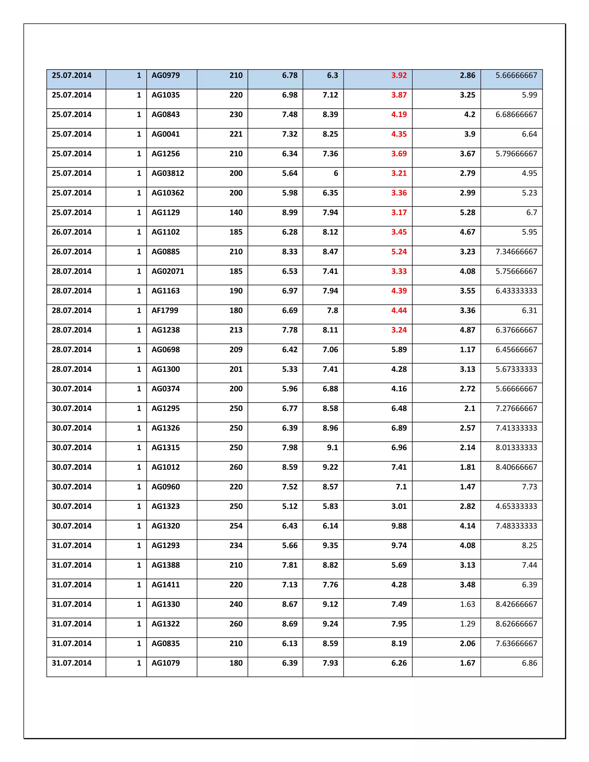
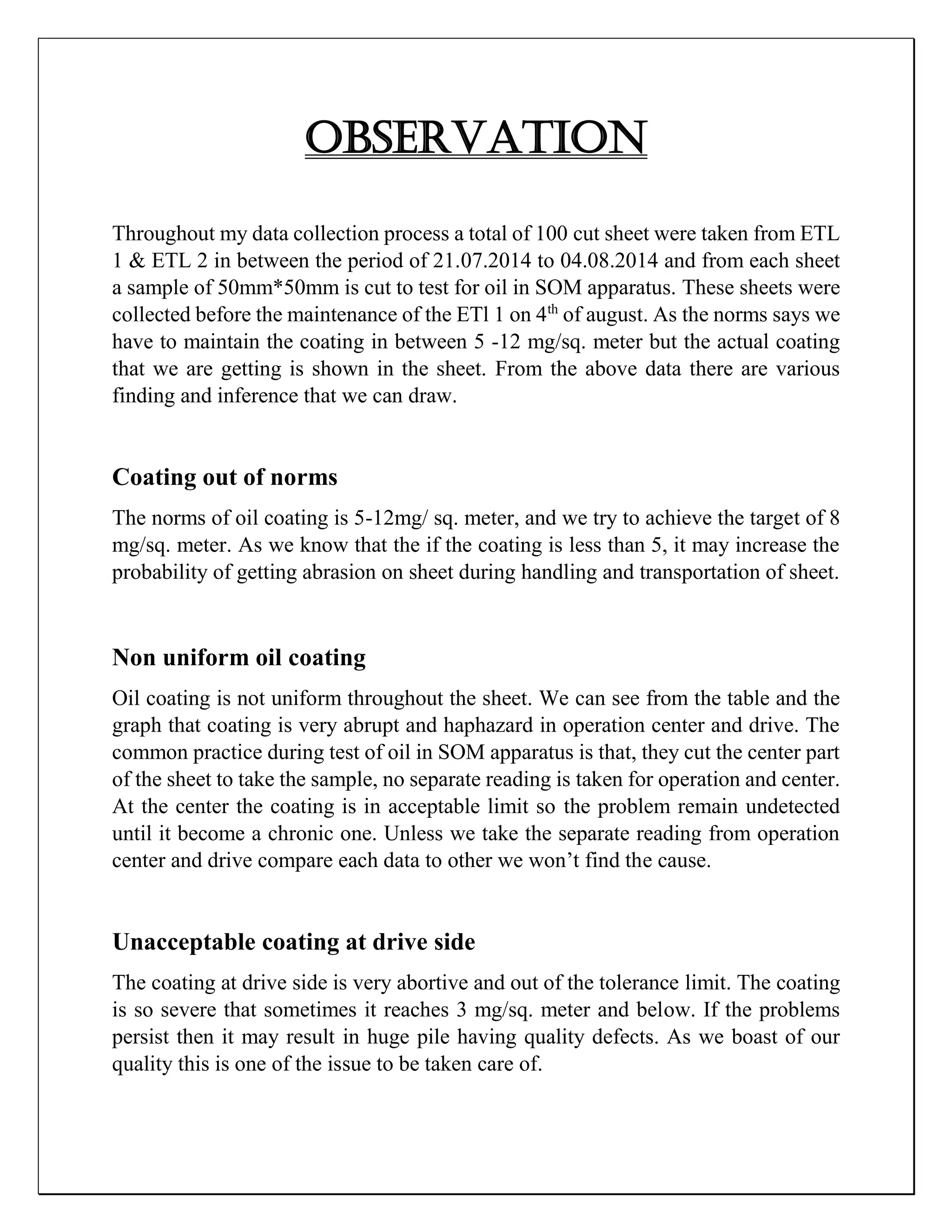
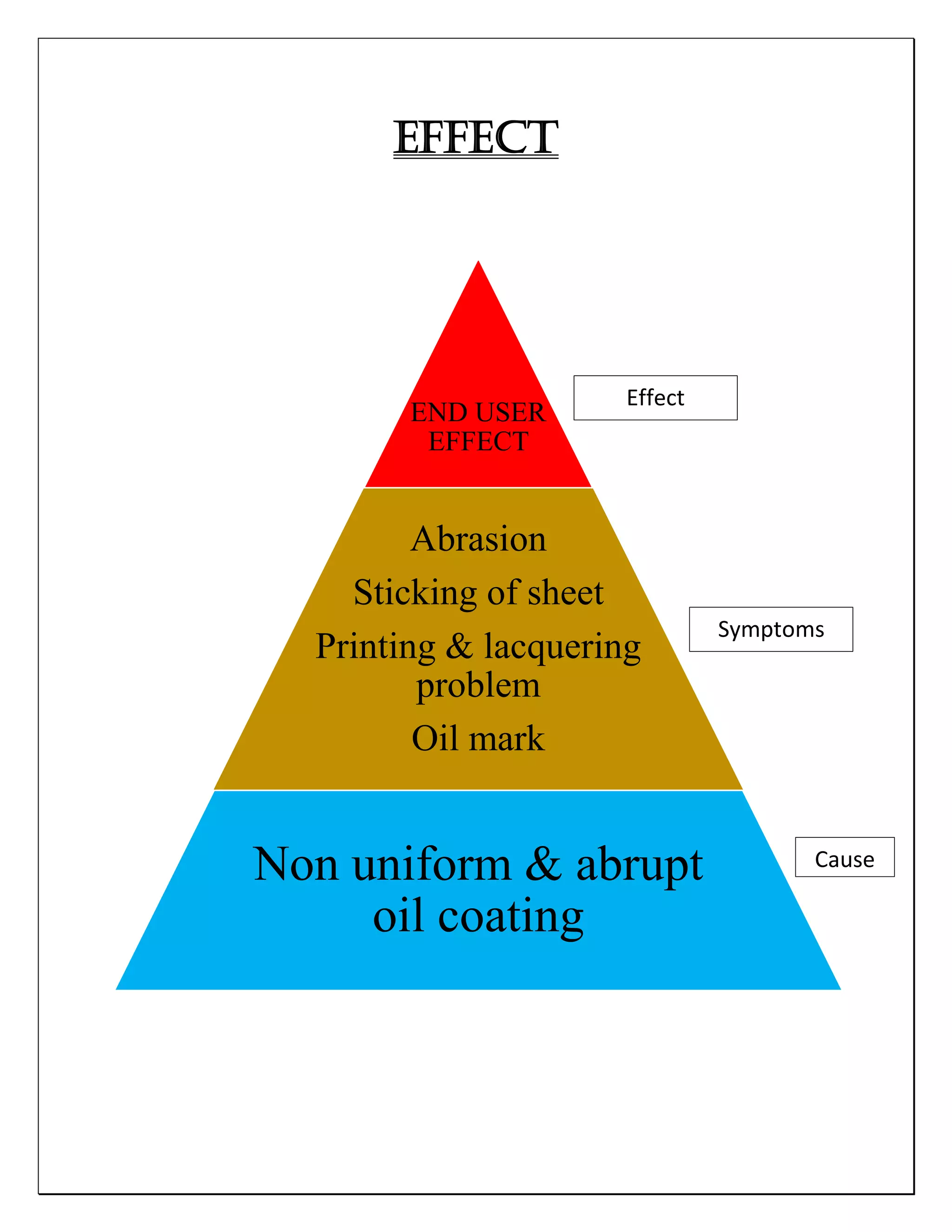
SlideShare a Scribd company logo
UP GRADATION
OF
TRION
ELECTROSTATIC
OILER
Submitted to: submitted by:
SUSHIL KUMAR, EBBIN DANIEL
Assistant manager (ETL),
Tinplate Company of India Limited (TCIL).
PREFACE
The oiler has a very critical role to play in the tinning line of our company. It help
in abrasion less handling of sheet, it doesn’t let the sheet in stack to stick to each
other. It also help in printing and lacquering of sheet at the solution center.
The Trion electrostatic fluid depositor is an electrostatic precipitation apparatus
design to deposit a micro thin film of protective, lubricating oil on a moving strip of
tin plated steel or other material at predetermine set weight ranging from 0.5 to 0.05
gm per base box regardless of equipment eliminates excess deposit of oil when the
line slowed to permit strip joining welds and also assures the desired oil deposit at
max operating speeds.
However, oiler is lagging in its basic functionality. The coating throughout the
sheet very deviant and out of norms. If this abrupt coating is not curbed now it may
result into various other problems and at last will hamper our product quality of the
finished goods.
As the norms says we have to maintain the coating in between 5 -12 mg/sq. meter
but the actual coating that we are getting a coating lesser than that due to various
reasons. This decreases the quality of the product.
However through a compatible and a very efficient maintenance system a uniform
coating of 5-12mg/sq. Meter can be achieved as per the given company norms.
ACKNOWLEDGEMENT
I would take this opportunity to thank Mr. Sushil Kumar, Assistant Manager of
Electroplating tinplating line (ETL) to give me an opportunity to work on this
project.
Throughout the period of the project I was given an opportunity to interact with
various people and get to know about various process been carried out within the
ETL division.
It enhanced my knowledge about various electrical process been carried out in the
Electroplating tinplating line (ETL).
Thus I am fully convinced that throughout my stay in Tinplate Company of India
Limited, I have gained a lot and has also given me an immense exposure in the the
field of electrical system within the company.
INDEX
 BEIF INTRODUCTION OF ETL
 TRION OILER
 OPERATION
 FLOW DIAGRAM
 IMPORTANCE
 SPECIFICATION
 SPREAD OIL MESURING APPARATUS
 DATA COLLECTION
 OBSERVATION
 EFFECTS
 PROBABLE CAUSE AND PREVENTIVE MAINTAINENCE
 RECOMMENDATION
 SHUT DOWN JOB LIST
 DATA COLLECTION AFTER SHUTDOWN
 OBSERVATION
BRIEF INTRODUCTION OF ETL
The unique properties of tin provide a coating on the steel that protects the contents,
while providing the steel with an attractive appearance, corrosion resistance and ease
in bonding, welding and painting. Tin is applied to both sides of the black plate coil
through an electrolytic process. The thickness of the tin coating (called coating
weight) is dependent upon the end-use application. Typical applications for
electrolytic tinplate include food and beverage containers, paint trays, battery tops
and paint, varnish and aerosol cans.
The Tinplate Company of India Limited pioneered the Indian Industry when they
put up the country's first tinning line in 1922. The growth of TCIL has been a
continuous process of development and modernization to keep Indian Tinplate at par
with international standards.
The technological advances had led to the introduction of Electrolytic Tinplate
(ETP), while the spiraling and prohibitive cost of tin resulted in the manufacture of
a suitable substitute, namely Tin Free Steel (TFS) or Electrolytic ally Chromium
coated steel (ECCS). To keep pace with these developments, TCIL was the first to
set up a combination line capable of producing both ETP and TFS. The plant was
commissioned in 1978 and has an installed capacity of 179000 tons per annum. The
line can be run up to a speed of 300 m/min and is capable of processing coils ranging
from 0.14 mm to 0.60 mm in thickness and 600 mm to 965 mm in width
The Electrolytic Tinplating line is the only one of its kind in India. It has a facility
to coat the line with tin or with chromium / chromium oxide (Tin Free Steel). The
ETP uses the FEROSTAN process, where in an acidic bath of Stannous Sulphate is
the electrolyte. The strip is "paid off" and passed through the looping tower - which
stores material to enable the line to run continuously, even while the entry is stopped
for welding the tail end of one coil to the head of the next. The strip then passes into
the cleaner solution to remove any remnant traces of oil or emulsion. Then it goes
through the pickling bath where the Sulphuric acid removes any oxide that may have
formed in the CRM complex. This acid also etches the plate, to prepare it for the
electro-deposition of tin. After the surface is fully prepared for plating it passes into
the plating section. Here the strip enters the bath with pure tin being used as anode
and the strip itself as the cathode. By passing the required direct current - this is
dependent on the coating weight required by the customer - in the bath the plate is
coated. Thereafter it passes into the melting furnace where the deposited tin is melted
to give it a brighter finish and also make it adhere to the base material better. After
this the strip is chemically treated to reduce the action of atmosphere on tin and then
coated with oil to facilitate handling.
In case the order is for tin free steel, the strip is passed directly from the pickling
bath to the chrome plating section. Here by using chromic acid bath and inert anodes
a layer each of chromium and chromium oxide is deposited on the strip. Since this
coated steel does not have any tin plating on its surface it is called tin free steel.
The strip is then passed through the online inspection to segregate any sheet that falls
outside the acceptable range of thickness, sheets with pinholes in them and then cut
up as per order and piled into packets of about 1500 KGs. This is then shipped out
to customers in trucks or containers, the latter mainly for overseas customers.
Process
ETL consists of various intermediate process which can be broadly classified as
follows.
 Entry
 Pre plating
 Plating
 Reflow unit
 Post plating
 Delivery
Now briefly looking at each section and its operation whose aggravated effects
leads to the tin plated sheet.
1. Entry section
2. Pre- Plating
The main sections of Pre- Plating are
 Pre Primary tank
 Primary cleaning
 Secondary cleaning
 Cleaning Rinse
 Pickling
 Pickling Dunk
 Pickling Rinse
Line Diagram
POR 1 POR 2
PINCH
ROLL 1
DOUBLE
CUT SHEAR
WELDER BURR
MESHER BRIDLE
NO1
LOOPER TOWER
PINCH
ROLL 2
CARRY
OVER
PINCH
ROLL
BRIDLE
NO1
DEFLECTOR
ROLL
STEERING
ROLL
CLEANING SECTION
PRE
PRIMA
RY
PRIMA
RY
SECON
DARY
RINSE PICKLI
NG
PICKLE
DUNK
DRIP
TRAY
RINSE
Fig -entry section
Fig – pre-plating section
CARRY-OVER ROLLS
ELECTROSTATICOILER
BRIDLE#3
PIN-HOLE
DETECTOR
DDS SHEAR
LOOP-PIT#3
Fig – Oiler, DDS
Fig – Delivery
TRION OILER
The Trion electrostatic fluid depositor is an electrostatic precipitation apparatus
design to deposit a micro thin film of protective, lubricating oil on a moving strip of
tin plated steel or other material at predetermine set weight ranging from 0.5 to 0.05
gm per base box regardless of equipment eliminates excess deposit of oil when the
line slowed to permit strip joining welds and also assures the desired oil deposit at
max operating speeds.
The Trion electrostatic fluid depositors consists of two identical plates of apparatus,
one on either sides of the tin strip and combine into one cabinet. Each has an oil
reservoir housing with built in nozzle system and secondary air manifold system, an
ionizer cartridge and repelling section .Both are controlled by common instrument
group and energized by one power pack.
The deposition of oil on the tin strip is accomplished in the following manner.
1. Oil particles of very small size are formed by spraying the oil through the set
of nozzles in the tank. The oil fog is forced to flow away from the nozzles and
around a baffle to eliminate large droplets from the fog.
2. A blower connected to secondary air piping supplies a controlled amount of
air to the fog tank and forces small droplets from the tank.
3. The oil particles are discharged through a slot in the top of the tank into the
ionizer section where the oil particles are charged electrically. Movable
shutters positioned below the discharged slot channel the passage of the fog
for various width of tin strip.
4. The charged oil particles are forced upward and inward towards the grounding
tin strip and into a high voltage field between tin strip and repelling plates.
5. A set of controlled instrument are furnished which senses the speed moving
tin strip and automatically adjust the discharged of secondary air blower
according to preset of deposit linearly with line speed producing uniform
deposit at any line speed from minimum to maximum.
Specification:
Repelling plate voltage: 50KV DC negative
Ionization voltage: 20KV DC negative
Recommended Oil: Shell Oil Company Diala-Ax
Di-electric strength of Oil: 35KV per 0.1 inch
OPERATION
Deflector roll
Tin strip
Access door
safety switch
each side
Insulating
baffle
Removable
ionizer
cartridge
Primary
air
manifold
Primary
air
nozzles
Deflector
roll
Secondary air
manifold
Adjustable shutter
Ionizing wires
TRION OILER
FLOW DIAGRAM
FORMATION OF SMALL OIL
DROPLETS
OIL FOG IS FORMED AROUND THE
BAFFLE
OIL FOG FURTHER ATOMIZES
BY PRIMARY AIR
ATOMIXED OIL CHARGED
WITH -20KV
SECONDRY AIR FORCE OIL
PARTICLES UPWARD
OIL PARTICLES ARE
REPELLED TOWARD SHEET
BY -50KV REPELLING PLATES
The electro–pneumatic control system combines two separate controlling
assemblies, ‘Air Flow Set Point’ and the ‘Air flow controller’, into one closed loop
control system. Once the operator has determined the type of oil to be deposited,
thickness of coating desired and the width of the strip to be passed through the
depositor, he needs only to refer to the ‘Oil weight versus Strip Width’ chart
furnished by Trion DOS oil and then adjust the valve position potentiometer to
correspond to the setting listed for these conditions.
The ‘Air flow controller’ will the automatically compensate for changes in line speed
to provide the constant oil coating desired. The line speed is measured by tachometer
generator which develops a dc voltage signal proportional to line speed.
The differential pressure resulting from secondary air passing through the variable
orifice valve is measured by differential pressure transmitter and resulting signal (0
to 300mmWC corresponds to 0 to 20 mA). This orifice can be varied by port valve
setting pot. There is control valve after the blower unit in the secondary air duct
before the port valve. The ‘line speed signal’ goes to a controller and accordingly a
controlled output signal rules the valve opening thus generating a ‘process value
signal’ which is displayed in the controller along with the ‘line speed signal’. Both
these values should ideally match. And the controller functions to match these
signals and accordingly open the control valve.
Power supply: There are two high voltages used, one is -50 KV DC & second one
is- 20 KV DC. These extremely high voltages are generated by stepping up the
voltage from 110 VAC to -20 KVDC and 220 VAC to -50 KVDC. Ionization voltage
basically used to ionize the oil fog / mist, formed by mixture of primary air and oil.
In ionization process, oil mist/fog break into positive and negative ion. Repelling
voltage (-50KV DC) repel the negative ion and forced to flow toward the sheet.
IMPORTANCE
Oiler is one of the critical section and if not taken care of it may leads to various
quality problems. Oiler importance can be listed as follows.
 It minimize subsequent damage by abrasion during packaging and
transportation of packed sheet.
 To facilitate assorting, handling, mechanical feeding and fabricating operation
 Aid in the lacquering and printing operation.
 Gives a glossy finish
.
TINPLATE SANDWICH
Oil Film
Passivation Layer
Tin
Alloy Layer
Steel Base
SPECIFICATION
Coating norms
5 -12 mg/sq meter. of DOS (for both sides).
Grounding Roll
Roll Dia. : 400.05 mm or 15.7 inches
Barrel Length : 1117.6 mm or 44 inches
Roll Shape : Cylindrical
Roll Material : STL & CHROME
Roll Mark : S
No. Of Rolls : 1
Deflector Roll
Roll Dia. : 406.4 mm or 16 inches
Barrel Length : 1117.6 mm or 44 inches
Roll Shape : Cylindrical
Roll Material : STL & HY-CAR
Roll Mark : W
No. Of Rolls : 2
Electrical Specifications:
Cartridge Voltage : 20 KV
Repelling Plate Voltage : 50 KV
Power supply : - 50 KV (-ve voltage to repelling plate)
-20 KV (-ve voltage to ionizer section)
Primary voltage ac
(volts)
Primary Current ac
(amperes)
Secondary voltage dc
(kilo volts)
42 18 10
85 34 20
148 54 30
173 58 40
221 64 50
CONTROL SYSTEM
Source of secondary air is a WESMAN BLOWER having a specification of
Power 1.5 H.P
Revolution 2500 RPM
Voltage 415V 3 phase
Frequency 50 cycle per second
LINE SPEED F/B
PID
I/P
20 PSI
PORT VALVE
PID
D.P.T
SECONDRYAIR
LINE
4-20 mAMPS
4-20 mAMPS
3 -15 PSI
TO THE OILER
The differential pressure resulting from the secondary air passing through the
variable orifice valve is measured by the differential pressure transmitter and the
resulting signal 4 to 20 milliamps is sent to the control station where a 250 ohm
Resistor that converts the current signal to 0 to 5v signal for the comparator
amplifier. The 0 to 5 v from the tachometer voltage divider and from the differential
pressure transmitter resistor are indicated on the front panel of the control station by
the line speed meter and process meter respectively. The output of the comparator
amplifier is amplified by the signal amplifier.
After that the line speed signal and the output of the differential pressure transmitter
is send to the PID (UDC 2500) controller input. Which takes the corrective measure
according to input signal and the output of 4-20 milliamps is send to the current to
pneumatic converter (I/P). This I/P converter has dedicated line of 15 psi. The output
of the I/P converter is dependent on the input current which is 4- 20 milliamps. The
output of the I/P converter is send to the control valve which can be opened and
closed with the pressure signal
Now whenever no compensation is needed after comparing the signal of line speed
and the differential pressure transmitter no signal is generated from the PID
controller and the control valve remain at the same position. Whenever there is
deficiency in flow or increase in line speed the valve is opened and compensate for
the flow and vice versa if there is increased in flow. In this way coating is controlled
at the variable line speed.
There is also a port valve control to increase or decrease the coating. It is a manual
control and generally placed at 60 – 70 % of manual opening. Suppose the coating
is below the norms then it can be increased by changing the position of the port
valve. A manual automation switch is provided on the front panel of the control
station to the manual operation can be accomplished for test and troubleshooting.
When the manual/automatic switch is in manual and the open/ close switch is
actuated a + or – 15 volts respectively is applied directly to the valve.
Interlocks
Primary air is supplied whenever the line speed us increased above 60MPM
-20kv and -50kv is also in interlock with the line speed, turns on when line speed is
increased above 60MPM
SPREAD OIL MEASURING
APPARATUS
As in our tinning line, antirust oil coating process such as DOS is available and the
quality control of the spread oil volume is performed.
This system measures precisely that small amount of oil coated on rolled steels
with the technique called “Hydrophilic Balance method” that adopts the typical
characteristics of oil spreading over water
Working principal
Most oils have property to spread over the water in monolayer status if the area is
large enough for oils to spread freely. The area that oil spreads should be in
proportion to the oil volume (numbers of oil molecules), if the density of the oil
molecules per unit area is kept evenly. Therefore, if we can control the density of oil
molecules when the oil spreads over the water, we can know the oil volume from the
spread area and experimental results obtained beforehand about their relations. Oil
molecules raise pressure when the distance of each molecule becomes close. It is
called Surface Film Pressure and that is why the oil molecules spread over the water
in monolayer status. (See Fig.1.) And the relation between the oil spread area and
the surface film pressure indicates a constant curve as the graph
DATA COLLECTION
After the complete study of the oiler of ETL 1. The second phase of the project was
started. This part mainly include the identification of the problem area, how much
adverse the problem is, before going to the rectification part the fact analysis is very
important.
So I started collecting samples from the ETL 1 & ETL 2 for problem identification
and comparison of the result of ETL 1 & ETL 2. At the initial step a total of 100
samples were tested for oil from the spread oil measurement system. From each sheet
3 samples were cut (operation, center and drive). The individual analysis of the sheet
is very much required to diagnosis of the cause of the problem and improve the
quality aspect of our product. Sheets were taken direct from hot running pile and
carefully handled to increase the accuracy of the result. During the process line speed
of the sheet is also noted to draw a correlation between the coating and line speed.
After the data collection process results were recorded and graphical analysis of the
data is also done for the individual area for the better understanding of the coating
on sheet.
Important things to note
Norms of coating 5-12 mg/sq. meter
Target of ETL 1 8 mg/sq. meter
Difference (max - min) < 0.35 mg/sq. meter
DATE ETL COIL Nos LINE SPEED
Coating (mg/sq. meter) DIFF = MAX-
MIN AVGoperation Center drive
21.07.2014 1 AG0835 210 6.13 8.59 8.19 2.06 7.63666667
21.07.2014 1 AG1079 180 6.39 7.93 6.26 1.67 6.86
21.07.2014 1 AF1748 180 6.36 7.85 6.29 1.56 6.83333333
21.07.2014 1 AG0883 220 8.32 9.98 7.58 2.4 8.62666667
21.07.2014 1 AF0186 200 7.6 8.13 7.29 0.84 7.67333333
21.07.2014 1 AF09762 200 6.12 8.47 6.3 2.35 6.96333333
21.07.2014 1 AG0448 190 8.68 8.12 7.36 1.32 8.05333333
22.07.2014 1 AG0838 210 8.89 8.97 8.83 0.14 8.89666667
22.07.2014 1 AG0922 200 7.94 8.69 7.47 1.22 8.03333333
22.07.2014 1 AG01079 178 8.58 9.1 8.2 0.9 8.62666667
22.07.2014 1 AG0704 200 6.36 6.98 8.63 2.27 7.32333333
22.07.2014 1 AG0214 220 5.63 6.22 5.1 1.12 5.65
22.07.2014 1 AG0799 240 6.24 7.09 6.01 1.08 6.44666667
22.07.2014 1 AG0801 240 5.47 7.58 8.54 3.07 7.19666667
23.07.2014 1 AG0308 220 7.91 8.83 9.93 2.02 8.89
23.07.2014 1 AG09802 200 7.49 8.76 7.18 1.58 7.81
23.07.2014 1 AG04181 190 7.98 9.01 7.36 1.65 8.11666667
23.07.2014 1 AG04181 190 8.14 9.16 7.68 1.76 8.32666667
23.07.2014 1 AG1856 221 8.72 9.41 8.1 1.31 8.74333333
23.07.2014 1 AG0385 221 7.84 8.78 9.9 2.06 8.84
23.07.2014 1 AG0962 185 8.36 9.08 7.32 1.76 8.25333333
23.07.2014 1 AG0882 190 8.14 8.32 6.29 2.03 7.58333333
23.07.2014 1 AG0452 215 8.97 8.9 8.92 0.07 8.93
24.07.2014 1 AG0961 140 4.94 7.09 4.8 2.29 5.61
24.07.2014 1 AG0961 140 4.17 8.04 6.35 3.87 6.18666667
24.07.2014 1 AG09581 190 5.87 6.74 4.86 1.88 5.82333333
24.07.2014 1 AG09491 215 5.66 6.41 4.21 2.2 5.42666667
24.07.2014 1 AG1008 220 5.86 6.25 6.64 0.39 6.25
25.07.2014 1 AG0952 180 6.53 7.73 3.5 4.23 5.92
25.07.2014 1 AG0979 214 6.53 6.35 3.18 3.35 5.35333333
25.07.2014 1 AG0979 210 6.78 6.3 3.92 2.86 5.66666667
25.07.2014 1 AG1035 220 6.98 7.12 3.87 3.25 5.99
25.07.2014 1 AG0843 230 7.48 8.39 4.19 4.2 6.68666667
25.07.2014 1 AG0041 221 7.32 8.25 4.35 3.9 6.64
25.07.2014 1 AG1256 210 6.34 7.36 3.69 3.67 5.79666667
25.07.2014 1 AG03812 200 5.64 6 3.21 2.79 4.95
25.07.2014 1 AG10362 200 5.98 6.35 3.36 2.99 5.23
25.07.2014 1 AG1129 140 8.99 7.94 3.17 5.28 6.7
26.07.2014 1 AG1102 185 6.28 8.12 3.45 4.67 5.95
26.07.2014 1 AG0885 210 8.33 8.47 5.24 3.23 7.34666667
28.07.2014 1 AG02071 185 6.53 7.41 3.33 4.08 5.75666667
28.07.2014 1 AG1163 190 6.97 7.94 4.39 3.55 6.43333333
28.07.2014 1 AF1799 180 6.69 7.8 4.44 3.36 6.31
28.07.2014 1 AG1238 213 7.78 8.11 3.24 4.87 6.37666667
28.07.2014 1 AG0698 209 6.42 7.06 5.89 1.17 6.45666667
28.07.2014 1 AG1300 201 5.33 7.41 4.28 3.13 5.67333333
30.07.2014 1 AG0374 200 5.96 6.88 4.16 2.72 5.66666667
30.07.2014 1 AG1295 250 6.77 8.58 6.48 2.1 7.27666667
30.07.2014 1 AG1326 250 6.39 8.96 6.89 2.57 7.41333333
30.07.2014 1 AG1315 250 7.98 9.1 6.96 2.14 8.01333333
30.07.2014 1 AG1012 260 8.59 9.22 7.41 1.81 8.40666667
30.07.2014 1 AG0960 220 7.52 8.57 7.1 1.47 7.73
30.07.2014 1 AG1323 250 5.12 5.83 3.01 2.82 4.65333333
30.07.2014 1 AG1320 254 6.43 6.14 9.88 4.14 7.48333333
31.07.2014 1 AG1293 234 5.66 9.35 9.74 4.08 8.25
31.07.2014 1 AG1388 210 7.81 8.82 5.69 3.13 7.44
31.07.2014 1 AG1411 220 7.13 7.76 4.28 3.48 6.39
31.07.2014 1 AG1330 240 8.67 9.12 7.49 1.63 8.42666667
31.07.2014 1 AG1322 260 8.69 9.24 7.95 1.29 8.62666667
31.07.2014 1 AG0835 210 6.13 8.59 8.19 2.06 7.63666667
31.07.2014 1 AG1079 180 6.39 7.93 6.26 1.67 6.86
OBSERVATION
Throughout my data collection process a total of 100 cut sheet were taken from ETL
1 & ETL 2 in between the period of 21.07.2014 to 04.08.2014 and from each sheet
a sample of 50mm*50mm is cut to test for oil in SOM apparatus. These sheets were
collected before the maintenance of the ETl 1 on 4th
of august. As the norms says we
have to maintain the coating in between 5 -12 mg/sq. meter but the actual coating
that we are getting is shown in the sheet. From the above data there are various
finding and inference that we can draw.
Coating out of norms
The norms of oil coating is 5-12mg/ sq. meter, and we try to achieve the target of 8
mg/sq. meter. As we know that the if the coating is less than 5, it may increase the
probability of getting abrasion on sheet during handling and transportation of sheet.
Non uniform oil coating
Oil coating is not uniform throughout the sheet. We can see from the table and the
graph that coating is very abrupt and haphazard in operation center and drive. The
common practice during test of oil in SOM apparatus is that, they cut the center part
of the sheet to take the sample, no separate reading is taken for operation and center.
At the center the coating is in acceptable limit so the problem remain undetected
until it become a chronic one. Unless we take the separate reading from operation
center and drive compare each data to other we won’t find the cause.
Unacceptable coating at drive side
The coating at drive side is very abortive and out of the tolerance limit. The coating
is so severe that sometimes it reaches 3 mg/sq. meter and below. If the problems
persist then it may result in huge pile having quality defects. As we boast of our
quality this is one of the issue to be taken care of.
Repeatability is not present
From repeatability I mean consistency. During my samples collection process I have
taken two different samples from the same coil at the same time (it is shown in blue
color in the chart) running at the same speed and tested for oil weight. There is a
visible difference between the two coatings in the drive side.
Coating is proportional to the line speed
Form the chart it can be infer that at center position the coating directly proportional
to the line speed. So whenever line speed increases the coating also increases and
vice versa.
Condition of repelling plates
As we know repelling plates provides the repelling force to the negatively charges
ions so it must be in proper condition to push the ions efficiently. During shutdown
of ETL 1, it is been observed that the repelling plates were covered with a thin and
sticky oil layer. As the repelling plates were covered there will be no repelling
voltage and no oil coating at the edges of sheet
Low efficiency
The efficiency of oil coating is very low in the Trion oiler. The aggravated efficiency
is about 40-60 % as compared to the GFG PEABODY oiler whose efficiency is
about 80%. Coating efficiency can be calculated by the fact that, oil consumption
from the tank, oil coated on sheet and oil exhausted in fumes.
EFFECT
END USER
EFFECT
Abrasion
Sticking of sheet
Printing & lacquering
problem
Oil mark
Non uniform & abrupt
oil coating
Cause
Symptoms
Effect
The oiler has a very critical role to play in the tinning line of our company. It help
in abrasion less handling of sheet, it doesn’t let the sheet in stack to stick to each
other. It also help in printing and lacquering of sheet at the solution center.
Now from the data observation report we can say that oiler is lagging in its basic
functionality. The coating throughout the sheet very deviant and out of norms. If this
abrupt coating is not curbed now it may result into various other problems and at last
will hamper our product quality of the finished goods. The problems associated with
abrupt oil coating and its effect can be described as follows
Coating lower than norms
Whenever the coating is decreased below the lower norms value it subsequently
increases the chances of getting abrasion on the sheet during handling and
transportation and at last number of rejection from the customer side may increases.
Coating above than norms
Similarly whenever the coating is increased above the norms the oxidizing nature
of oil increases and the oil start forming amines that is very sticky in nature and has
foul odor and bad taste. So due to this the purpose of using oiler will be lost in vein.
Oil that is used for preventing the sheet from sticking, after oxidizing it starts helping
sticking.
Oil mark
Excess oil on the sheet also creates problem during printing and lacquering of sheet.
Its results in oil marks problems on the sheet and also forms and eye hole type marks
that shows that paint do not adhere on it
Printing & lacquering problem
Sometimes the sticking of sheets starts creating problems in our printing and
lacquering line, as the printing and lacquering consist of a suction that helps in
selecting one sheet only, excess oil will make the sheet stick to each other and double
sheet selection starts. So due to this double sheet selection lacquer cannot be coated
in between the two sheets
These problems are only symptoms of very chronic problem if not taken care of, if
we want to make our product high of quality aspect
PROBABLE CAUSE &
PREVENTIVE MAINTAINENCE
Abruptoilcoating
Removed Side Plates
Choked Nozzle
Cartidge Issue
No Control System
Trial & Error
Adjustment
Low Efficiency
Oil Flow
Secondry Air Flow
Primary Air Flow
ETL 1 MASTER MAINTAINENCE
LIST
The maintenance list shows the frequency of the cleaning of TRION OILER along
with other equipment list. This is the main master maintenance list that is commonly
followed. From the list it is seen that the maintenance of the repelling plates is done
in the monthly basis and the maintenance of the nozzles, oil tank and overflow tank
is done on the quarterly basis. There can be various amendments can be done in the
maintenance schedule list to improve the effectiveness of the oiler.
Removed shutter plates
Sheet
Repelling plates
Side plates
Sheet
Repelling plates
Side plates
Wider width coil
Smaller width coil
The side plates which was previously present in the system to adjust according to
the strip width is not functional now a days. It leads to a very critical coating
problem. Whenever the shorter width coil is running the repelling plates also got
coated with the oil mist and with time this oil mist is converted into thick sticky oil
layer. This thick layer reduces the efficiency of the repelling plates to repel the
charged oil particles to the sheet. So whenever the wider width coil starts running
the repelling action at the edges is reduced and operation and drive side of the coil
will be bereft of the oil coating or very less coating occurs.
During the data collection process, it is being observed that whenever the shorter
width is running continuously compared to the wider width the repelling plates are
getting covered more frequently and there is no measure to clean the repelling plates
before the next shutdown. So in between that all the wider width will be deficient of
the oil coating at the edges. The cleaning frequency of the repelling plates now a
days is in shutdown or in breakdown only.
Recommendation
Being observing the repelling plates on daily basis, it is seen that cleaning frequency
now a days follows this trend,
Maintenance
CURRENT PROCESS
Cleaning In shut down or in breakdown only in
monthly basis
Checking of sheet Mostly center part is checked
STRONGLY RECOMMENDED
Cleaning On the opportunity basis or weekly
Inspection Daily
Checking of sheet Random samples should be taken and
operation center and drive should be
checked for oil
Chocked Nozzle
These nozzles were primarily used for spraying the oil into the system and creating
oil mist that were further ionized by the cartridge having -20 Kv. These nozzles are
equipped with filter element to separate the oil with fine soluble particles. These
filter are the last filtering element in the whole system and after the oil is released
into the system oil droplets of very small size are formed by spraying the oil through
the set of nozzles in the tank. The oil fog is forced to flow away from the nozzles
and around a baffle to eliminate large droplets from the fog. Movable shutters
positioned below the discharged slot channel the passage of the fog for various width
of tin strip.
The DOS that we use for the oil coating are inevitably got contaminated with fine
insoluble particles and sometimes the particles of very small size escapes from the
primary filtration and get stuck to the nozzles filter. Due to this sometimes part of
the nozzle or the whole nozzle get chocked up and create problem in spraying oil
into the system. Coating does occur in a straight in the rolling direction of the whole
sheet and affect the quality of the product. This quality defect cannot be determined
until we do the random check of the whole sheet in matrix form and persist for many
days until the next shutdown or breakdown the coating got affected.
RECOMENDATION
As spraying system is very critical and determine the quality of coating the nozzle
should be in proper working condition.
Maintenance
Current process
Cleaning In quarterly basis on in breakdown
Checking Oil mist formation is checked by
opening the observing window but no
system to identify which nozzle has
problem
Should be followed
Cleaning On opportunity basis or in monthly
basis
Checking The whole sheet should be checked in a
matrix form and at least 9 samples
should be taken, 3 from each, operation
center and drive. So if the deficiency is
occurring in straight of rolling direction
then that particular nozzle may be
probable cause
Cartridge Problems
 Material: Tungsten 99.95%
 Diameter: .007" (.18mm)
 Length: 100' (30.5m) min.
 Resistance (at 20°C): 2.16 Ω/m
 Resistance (at 2027°C): 26.29 Ω/m
 Finish: Bright
 Original Shape: Straightened
The cartridge are mainly used in the ionizing section to ionize the oil mist particles
to a charge of -20Kv. Then the ionized particles are moved upward with the help of
secondary air and then repelled by the repelling plates. If the cartridge are not
working properly or if the cartridge wire is broken then oil particles will not be
ionized and will leave the oiler cabin without being used. This has very critical effect
on the coating as coating is primarily dependent on the electrostatic process and
repelling of -20Kv charged oil particles by -50Kv repelling plates, so it reduces the
efficiency of the oiler drastically and coating does not occur properly. Due to this
snag oil being used will be same but the coating is abortive.
Due to the continuous use of cartridge, the insulation between the cartridge wires
that separates them from each other and prevent shorting of wires. This insulation
also got coated with the thick oil layer. The oil layer on the insulation is a very
critical reason of the cartridge breaking. Whenever the insulation is deposited with
oil layer the wires get shorted and current start flowing. The wires get heated up
which leads to the breaking of wire
Since the oil particles are charged to the voltage of -20Kv, due to the repelling force
between them they do not combine or adhere to each other to form large oil droplets
but when the cartridge wire is broken they do not help in charging the oil particles
and these particles adhere to other particles to form oil droplets. The droplet
formation is cumulative in nature. These oil droplets either precipitate near the
bottom of the oiler or create oil mark on the sheet thus creating quality defect of the
finished products.
Identifying cartridge breakage
 High fumes generation
 Current fluctuation
RECOMENDATION
Maintenance
Current process
Should be followed
Cartridge Changing If there is breakdown or in shutdown
Primary Air Flow
The source of primary air is compressed air at pressure of 6.2 Kg/cm2.
This
compressed air is first passed through the refrigerant type dryer to remove the
moisture at the primary stage. The primary air of the oiler also consist of moisture
separator that helps in removing moisture that occur due to the condensation of fine
droplets in the compressed air. This moisture separator also consist of default filter
element to remove the unwanted particles to get into the oiler and affect the mist
formation process. After the moisture separator there is a regulator to keep the
pressure of the primary air at 0.7 Kg/cm2
(8 PSI approx.). This much pressure is
necessary to keep air oil mixture in balance.
Specification of pressure switch
Type TGS 111-NO31
Contact point 181b
Pressure range .02 - .3Mpa
Different range .015 – 0.2Mpa
MFG. Number 1336052
Year 2013
Last check 04.04.2014
Specification of pressure switch
Body STEEL
Cartridge IMPORTED S.S.
Size 1 inch
Working pressure UPTO 16 BAR
Efficiency 99.99%
Testing pressure 24 BAR
Service life MIN. EXP. 8 TO 10 YRS
Last check 04.04.2014
The quality and efficiency of the primary air to form the oil mist is very much
dependent on the functioning of the moisture separator and the pressure regulator. If
the moisture separator do not remove the moisture before injecting into the system
it create oil spot problem on the sheet which may further affect in painting and
lacquering at solution center. The dust particle in the primary air also affect the
atomization of the oil particles. Further the oil mist forming capability in dependent
on the pressure also, if the pressure is high then mist is converted into fog which is
denser and due to that large number of oil particles will leave the oiler chamber
unused and thus decreasing the efficiency of the oiler.
Problem associated with the primary air is that moisture separator has to be drained
every day morning shift only. The problem with this maintenance system is that in
humid atmosphere the rate of moisture formation is high and it may start affecting
the oil mist formation.
Recommendation
Maintenance check list for primary air
This check list should be followed for the better conditioning of the primary air and
in result better oil coating result.
Primary air
equipment
Norms Actual Remarks
Air pressure switch
reading
Should be 8Psi
Moisture separator
draining
Should be cleaned
in every shift
 Activated alumina used as an absorbent type of dryer prior the moisture
separator. Moisture laden air is passed through a tank containing a chemical
that absorbs the moisture similar to common table salt absorbing water and
forms a solution that is drained from the bottom of the tank. These chemical
need to be replaced time to time to maintained the efficiency of the dryer.
Secondly this type of dryer has a problem of chemical carry over with the
compressed air. So these dryer should be cleaned time to time to eliminate the
chances of chemical carry over or moisture carry over
 Secondary Air Flow
Source of secondary air is a WESMAN BLOWER having a specification of
Power 1.5 H.P
Revolution 2500 RPM
Voltage 415V 3 phase
Frequency 50 cycle per second.
Oil flow
Oil flow is constant throughout the coating. There is no system to control the oil
flow according to the line speed or to check the precision and amount of oil that
flows to the system. If we can control the oil flow then we can also control the
coating in the direct manner. As we seen that there is a direct relation between the
line speed and the coating. Then that means we requires variable flow of oil
according to the
SHUTDOWN JOB LISTS
ETL 1 has gone through shutdown on 4th
of august. As we have seen from the data
that there is abrupt oil coating through the sheet. To identify decode and rectify the
problem some job list have been planned. The major concern area was drive side in
which coating is very low and not within the norms.
Job lists
 Cleaning of repelling plates
 Nozzle cleaning
 Cartridge changing
 Primary air pressure switch checking
 Secondary –air, port valve position checking
 DOS tank checking
DATA COLLECTION AFTER SHUTDOWN
date coil number speed operation center DRIVE
5.08.2014 AG1529 168
6.14 7.76 6.36
6.22 7.78 6.36
6.2 7.78 6.35
05.08.2014 AG16202 183
6.14 7.2 5.98
6.25 7.13 6.03
6.2 7.13 6.1
05.08.2014 AG16202 183
6.01 7.03 5.95
5.99 7.03 5.98
6.01 7.01 5.98
06.08.2014 AG16092 200
7.47 8.82 7.52
7.46 8.81 7.47
7.45 8.8 7.5
06.08.2014 AG15142 196
7.69 8.4 7.37
7.84 8.51 7.26
7.62 5.37 7.4
06.08.2014 AG1636 200
8.1 8.6 7.65
8.15 8.56 7.63
7.97 8.52 7.75
06.08.2014 AG15142 200
8.29 8.89 7.71
8.35 8.76 7.64
8.3 8.85 7.52
06.08.2014 AG15822 210
6.59 8.65 6.13
6.6 8.65 6.15
6.6 8.66 6.13
07.08.2014 AG16272 200
7.14 7.65 6.83
7.2 7.76 6.9
7.21 7.6 6.9
07.08.2014 AG16272 200
7.14 7.3 6.77
7.14 7.48 6.6
7.2 7.25 6.48
07.08.2014 AG1532 211
7.18 7.83 6.66
7.2 7.96 6.59
7.1 7.84 6.7
07.08.2014 AG15491 200
5.95 7.5 6.09
5.8 7.47 6.1
5.96 7.51 6.08
08.08.2014 AG0162 230
7.12 9.2 6.6
7.13 9.23 6.62
7.1 9.23 6.6
08.08.2014 AH0169 221 7.85 8.44 7.3
7.96 8.48 7.45
7.9 8.6 7.22
08.08.2014 AG0088 185
5.01 6.2 5.35
4.95 6.22 5.35
4.99 6.22 5.36
08.08.2014 AH0193 220
7.14 7.94 6.73
7.26 7.88 6.5
7.26 7.9 6.56
08.08.2014 AH0227 230
7.4 8.91 7.36
7.4 8.9 7.4
7.42 8.9 7.4
09.08.2014 AG1744c 142
3.96 5.83 3.88
3.93 5.82 3.9
3.9 5.82 3.9
09.08.2014 AF17172 175
5.45 6.21 5.11
5.4 6.21 5.1
5.42 6.21 5.1
10.08.2014 AG03582 181
4.96 6.35 3.96
4.98 6.35 3.99
4.98 6.36 3.99
10.08.2014 AF18392 201
5.21 6.71 4.8
5.21 6.77 4.83
5.21 6.75 4.82
11.08.2014 AF0868 200
6.39 8.11 4.88
6.42 8.1 4.9
6.42 8.13 4.9
11.08.2014 AH0321 210
6.58 7.76 5.27
6.58 7.85 5.18
6.62 7.6 5.18
12.08.2014 AF1751 230
6.67 8.47 6.8
6.68 8.42 6.82
6.65 8.45 6.8
12.08.2014 AG0095 210
6.84 7.76 5.89
6.8 7.76 5.92
6.8 7.76 5.91
13.08.2014 AG00492 200
6.11 7.6 4.96
6.1 7.63 4.98
6.1 7.64 4.98
13.08.2014 AG0434 130
6.41 8.18 6.28
6.4 8.2 6.21
6.4 8.16 6.23
OBSERVATION
ETl 1 has gone through shutdown on 4th
of august. Seeing a vast difference between
the maximum and minimum coating and very abrupt coating on the sheet. Various
job related to oiler has been planned as we have discussed above. After the shutdown
again the data collection process stated to analyze the effect of the job.
In this a more thorough analysis of the sheet has been done. A particular sheet was
divided into 9 parts. 3 samples from each operation center and drive. This is done to
check
1. Uniformity
2. Linearity( coating in a particular line)
3. Difference of each individual part.
1 2
6
3
987
4 5
Operation Center Drive
Inference that can be drawn from the data
Lead indicator
 The initial results of the coating weight measurement shows a palpable
improvement. Coating is well within the norms (5-12mg/sq. meter) of the
initial results.
 Linearity is present in all the samples. Either take it operation center or drive,
coating in the straight line of the rolling direction almost constant. So there is
problem regarding the coating in the straight line.
 This time also, two samples from a particular sheet running at the same line
speed is taken. The coating in both the sheets were almost same. As in the
previous case of data collection, the two different samples from the same sheet
shows a major variation due to the chocked nozzles and irregular air oil ratio.
So this time the problem has been mostly curbed by the proper maintenance.
Conclusion
The project can be concluded by saying that the oiler is lagging in its
basic functionality. The coating throughout the sheet very deviant and
out of norms. If this abrupt coating is not curbed now it may result into
various other problems and at last will hamper our product quality of the
finished goods.
As the norms says we have to maintain the coating in between 5 -12
mg/sq. meter therefore achieving a uniform thickness of 5-
12mg/sq.meter is our only target.
However the system can be improved by the following process:-
 Effective maintenance
 Proposing a new system for oil coating.
 Changing the existing system
Now we are considering the “effective maintenance” as our tool for
improving the system as it fits in our budget.
Therefore a weekly shutdown is planned for ETL-1 every Tuesdays for
maintenance purpose thereby achieving a uniform thickness of 5-
12mg/sq.meter.

More Related Content

What's hot

Manufacturing & Applications of Stainless Steels
Manufacturing & Applications of Stainless SteelsManufacturing & Applications of Stainless Steels
Manufacturing & Applications of Stainless Steels
Venkataraman Bandaru
 
Hot Rolling And cold rolling process
Hot Rolling And cold rolling processHot Rolling And cold rolling process
Hot Rolling And cold rolling process
Dhyey Shukla
 
Laser beam hardening
Laser beam hardeningLaser beam hardening
Laser beam hardening
BIBIN EMMANUVEL
 
Reheating Furnace in Rolling Mill Industries
Reheating  Furnace in Rolling Mill IndustriesReheating  Furnace in Rolling Mill Industries
Reheating Furnace in Rolling Mill Industries
Vikas Yadav
 
Jominy end quench hardenability test
Jominy end quench hardenability testJominy end quench hardenability test
Jominy end quench hardenability test
Tejas Atyam
 
Alloy Steel
Alloy SteelAlloy Steel
Alloy Steel
Akash Patel
 
Cast Iron
Cast IronCast Iron
Cast Iron
Akash Patel
 
Continious casting of steel
Continious casting of steelContinious casting of steel
Continious casting of steel
bikiranjan
 
Secondary steel making processes
Secondary steel making processesSecondary steel making processes
Secondary steel making processes
chandrakant jally
 
BASIC OXYGEN STEELMAKING (BOS) - The Processing Route (blast furnace - basic ...
BASIC OXYGEN STEELMAKING (BOS) - The Processing Route (blast furnace - basic ...BASIC OXYGEN STEELMAKING (BOS) - The Processing Route (blast furnace - basic ...
BASIC OXYGEN STEELMAKING (BOS) - The Processing Route (blast furnace - basic ...
Matteo Sporchia
 
Study of Plain Carbon Steel
Study of Plain Carbon Steel Study of Plain Carbon Steel
Study of Plain Carbon Steel
Hardik Sakpal
 
Mitsubishi cnc drive system general catalog (mds e-eh-em-ej-ejh series) dienh...
Mitsubishi cnc drive system general catalog (mds e-eh-em-ej-ejh series) dienh...Mitsubishi cnc drive system general catalog (mds e-eh-em-ej-ejh series) dienh...
Mitsubishi cnc drive system general catalog (mds e-eh-em-ej-ejh series) dienh...
Dien Ha The
 
Alloy steel
Alloy steelAlloy steel
Alloy steel
Arathi Krishna
 
Ductile iron
Ductile ironDuctile iron
Ductile iron
NIAJ AHMED
 
If steels final
If steels finalIf steels final
If steels final
bandaru pravallika
 
Sinter Plant,Lime & Dolo Plant industrial Training Report
Sinter Plant,Lime & Dolo Plant industrial Training ReportSinter Plant,Lime & Dolo Plant industrial Training Report
Sinter Plant,Lime & Dolo Plant industrial Training Report
Shani Kumar Singh
 

What's hot (20)

Steel Making: Ingot casting defects
Steel Making: Ingot casting defectsSteel Making: Ingot casting defects
Steel Making: Ingot casting defects
 
Manufacturing & Applications of Stainless Steels
Manufacturing & Applications of Stainless SteelsManufacturing & Applications of Stainless Steels
Manufacturing & Applications of Stainless Steels
 
Hot Rolling And cold rolling process
Hot Rolling And cold rolling processHot Rolling And cold rolling process
Hot Rolling And cold rolling process
 
Faisal
FaisalFaisal
Faisal
 
Laser beam hardening
Laser beam hardeningLaser beam hardening
Laser beam hardening
 
Reheating Furnace in Rolling Mill Industries
Reheating  Furnace in Rolling Mill IndustriesReheating  Furnace in Rolling Mill Industries
Reheating Furnace in Rolling Mill Industries
 
Jominy end quench hardenability test
Jominy end quench hardenability testJominy end quench hardenability test
Jominy end quench hardenability test
 
Alloy Steel
Alloy SteelAlloy Steel
Alloy Steel
 
Cast Iron
Cast IronCast Iron
Cast Iron
 
Continious casting of steel
Continious casting of steelContinious casting of steel
Continious casting of steel
 
Electric arc furnace
Electric arc furnaceElectric arc furnace
Electric arc furnace
 
Secondary steel making processes
Secondary steel making processesSecondary steel making processes
Secondary steel making processes
 
BASIC OXYGEN STEELMAKING (BOS) - The Processing Route (blast furnace - basic ...
BASIC OXYGEN STEELMAKING (BOS) - The Processing Route (blast furnace - basic ...BASIC OXYGEN STEELMAKING (BOS) - The Processing Route (blast furnace - basic ...
BASIC OXYGEN STEELMAKING (BOS) - The Processing Route (blast furnace - basic ...
 
Study of Plain Carbon Steel
Study of Plain Carbon Steel Study of Plain Carbon Steel
Study of Plain Carbon Steel
 
Mitsubishi cnc drive system general catalog (mds e-eh-em-ej-ejh series) dienh...
Mitsubishi cnc drive system general catalog (mds e-eh-em-ej-ejh series) dienh...Mitsubishi cnc drive system general catalog (mds e-eh-em-ej-ejh series) dienh...
Mitsubishi cnc drive system general catalog (mds e-eh-em-ej-ejh series) dienh...
 
Bos
BosBos
Bos
 
Alloy steel
Alloy steelAlloy steel
Alloy steel
 
Ductile iron
Ductile ironDuctile iron
Ductile iron
 
If steels final
If steels finalIf steels final
If steels final
 
Sinter Plant,Lime & Dolo Plant industrial Training Report
Sinter Plant,Lime & Dolo Plant industrial Training ReportSinter Plant,Lime & Dolo Plant industrial Training Report
Sinter Plant,Lime & Dolo Plant industrial Training Report
 

Viewers also liked

OST - TCIL final
OST - TCIL finalOST - TCIL final
OST - TCIL final
Saurabh Sarkar
 
TCIL: Need for Conceptual Focus
TCIL: Need for Conceptual FocusTCIL: Need for Conceptual Focus
TCIL: Need for Conceptual Focus
Ankan JBz
 
Wandres+dietronic light
Wandres+dietronic lightWandres+dietronic light
Wandres+dietronic light
Giovanni Amato
 
Tinplate company of india
Tinplate company of indiaTinplate company of india
Tinplate company of india
Fajar Muhammad
 
Tata Tinplate Company of India Ltd
Tata Tinplate Company of India LtdTata Tinplate Company of India Ltd
Tata Tinplate Company of India Ltd
Sonali Srivastava
 
Oil Measuring Apparatus- OMA
Oil Measuring Apparatus- OMAOil Measuring Apparatus- OMA
Oil Measuring Apparatus- OMA
Jimmy Hsu
 
Oil measuring apparatus(oma) catalogue
Oil measuring apparatus(oma) catalogueOil measuring apparatus(oma) catalogue
Oil measuring apparatus(oma) catalogue
Jimmy Hsu
 
Guide to tinplate
Guide to tinplateGuide to tinplate
Guide to tinplate
Tony Wallace
 
Surfactants
Surfactants Surfactants
Surfactants
sachinpatel5912
 
Trioa Electrostatic Oiler Brohure
Trioa Electrostatic Oiler BrohureTrioa Electrostatic Oiler Brohure
Trioa Electrostatic Oiler Brohure
Jimmy Hsu
 
2015 Upload Campaigns Calendar - SlideShare
2015 Upload Campaigns Calendar - SlideShare2015 Upload Campaigns Calendar - SlideShare
2015 Upload Campaigns Calendar - SlideShare
SlideShare
 
What to Upload to SlideShare
What to Upload to SlideShareWhat to Upload to SlideShare
What to Upload to SlideShare
SlideShare
 
Getting Started With SlideShare
Getting Started With SlideShareGetting Started With SlideShare
Getting Started With SlideShare
SlideShare
 

Viewers also liked (13)

OST - TCIL final
OST - TCIL finalOST - TCIL final
OST - TCIL final
 
TCIL: Need for Conceptual Focus
TCIL: Need for Conceptual FocusTCIL: Need for Conceptual Focus
TCIL: Need for Conceptual Focus
 
Wandres+dietronic light
Wandres+dietronic lightWandres+dietronic light
Wandres+dietronic light
 
Tinplate company of india
Tinplate company of indiaTinplate company of india
Tinplate company of india
 
Tata Tinplate Company of India Ltd
Tata Tinplate Company of India LtdTata Tinplate Company of India Ltd
Tata Tinplate Company of India Ltd
 
Oil Measuring Apparatus- OMA
Oil Measuring Apparatus- OMAOil Measuring Apparatus- OMA
Oil Measuring Apparatus- OMA
 
Oil measuring apparatus(oma) catalogue
Oil measuring apparatus(oma) catalogueOil measuring apparatus(oma) catalogue
Oil measuring apparatus(oma) catalogue
 
Guide to tinplate
Guide to tinplateGuide to tinplate
Guide to tinplate
 
Surfactants
Surfactants Surfactants
Surfactants
 
Trioa Electrostatic Oiler Brohure
Trioa Electrostatic Oiler BrohureTrioa Electrostatic Oiler Brohure
Trioa Electrostatic Oiler Brohure
 
2015 Upload Campaigns Calendar - SlideShare
2015 Upload Campaigns Calendar - SlideShare2015 Upload Campaigns Calendar - SlideShare
2015 Upload Campaigns Calendar - SlideShare
 
What to Upload to SlideShare
What to Upload to SlideShareWhat to Upload to SlideShare
What to Upload to SlideShare
 
Getting Started With SlideShare
Getting Started With SlideShareGetting Started With SlideShare
Getting Started With SlideShare
 

Similar to TCIL_PROJECT

Tbea vocatinal training
Tbea vocatinal trainingTbea vocatinal training
Tbea vocatinal training
Deep Shah
 
PCB Manufacturing Process.docx
PCB Manufacturing Process.docxPCB Manufacturing Process.docx
PCB Manufacturing Process.docx
09JameelAhmedJ
 
Thermal barrier coating seminar
Thermal barrier coating seminarThermal barrier coating seminar
Thermal barrier coating seminar
DebendraMeher1
 
Interra presentation for mechanical activities
Interra presentation for mechanical activities Interra presentation for mechanical activities
Interra presentation for mechanical activities
Ayman bolty
 
Effect of thermal barrier coating for the improvement
Effect of thermal barrier coating for the improvementEffect of thermal barrier coating for the improvement
Effect of thermal barrier coating for the improvement
eSAT Publishing House
 
Effect of thermal barrier coating for the improvement of si engine performanc...
Effect of thermal barrier coating for the improvement of si engine performanc...Effect of thermal barrier coating for the improvement of si engine performanc...
Effect of thermal barrier coating for the improvement of si engine performanc...
eSAT Journals
 
Industrial visit report uttam transformers
Industrial visit report  uttam transformersIndustrial visit report  uttam transformers
Industrial visit report uttam transformers
MahipalSoni4
 
Panel
PanelPanel
12BME1107-ABOUT THE COMPANY
12BME1107-ABOUT THE COMPANY12BME1107-ABOUT THE COMPANY
12BME1107-ABOUT THE COMPANYNaman Sharma
 
GEMCO(general electric manufacturing company),chittagong,bd
GEMCO(general electric manufacturing company),chittagong,bdGEMCO(general electric manufacturing company),chittagong,bd
GEMCO(general electric manufacturing company),chittagong,bd
Tanvir Shihan
 
PPE Demo Report by Tuan Afaham Burah
PPE Demo Report by Tuan Afaham BurahPPE Demo Report by Tuan Afaham Burah
PPE Demo Report by Tuan Afaham BurahTuan Afaham Burah
 
Corrosion? No thanks...
Corrosion? No thanks...Corrosion? No thanks...
Corrosion? No thanks...
Bárbara Gregorio Bondía
 
Transpower Switchgear Industries, Mumbai, Electrical Products
Transpower Switchgear Industries, Mumbai, Electrical ProductsTranspower Switchgear Industries, Mumbai, Electrical Products
Transpower Switchgear Industries, Mumbai, Electrical Products
IndiaMART InterMESH Limited
 
THERMAL BARRIER COATINGS Nagesh bhagwan shejol ppt
THERMAL BARRIER COATINGS Nagesh bhagwan shejol ppt THERMAL BARRIER COATINGS Nagesh bhagwan shejol ppt
THERMAL BARRIER COATINGS Nagesh bhagwan shejol ppt
Nagesh shejol
 
Transformer ppt
Transformer pptTransformer ppt
Transformer ppt
Rakesh Gurjar
 
Producing and fabricating titanium.pdf
Producing and fabricating titanium.pdfProducing and fabricating titanium.pdf
Producing and fabricating titanium.pdf
LeoZhao25
 
RAUTOMEAD TECHNOLOGY FOR CONTINUOUS CASTING OF OXYGEN-FREE COPPER AND DILUTE...
RAUTOMEAD  TECHNOLOGY FOR CONTINUOUS CASTING OF OXYGEN-FREE COPPER AND DILUTE...RAUTOMEAD  TECHNOLOGY FOR CONTINUOUS CASTING OF OXYGEN-FREE COPPER AND DILUTE...
RAUTOMEAD TECHNOLOGY FOR CONTINUOUS CASTING OF OXYGEN-FREE COPPER AND DILUTE...
Rautomead Limited
 
WELD POSTCLEEN PRESENTATION
WELD POSTCLEEN PRESENTATIONWELD POSTCLEEN PRESENTATION
WELD POSTCLEEN PRESENTATIONweldpost
 
Industrial training report
Industrial training report Industrial training report
Industrial training report Pritam Samanta
 

Similar to TCIL_PROJECT (20)

Tbea vocatinal training
Tbea vocatinal trainingTbea vocatinal training
Tbea vocatinal training
 
PCB Manufacturing Process.docx
PCB Manufacturing Process.docxPCB Manufacturing Process.docx
PCB Manufacturing Process.docx
 
Thermal barrier coating seminar
Thermal barrier coating seminarThermal barrier coating seminar
Thermal barrier coating seminar
 
Interra presentation for mechanical activities
Interra presentation for mechanical activities Interra presentation for mechanical activities
Interra presentation for mechanical activities
 
Effect of thermal barrier coating for the improvement
Effect of thermal barrier coating for the improvementEffect of thermal barrier coating for the improvement
Effect of thermal barrier coating for the improvement
 
Effect of thermal barrier coating for the improvement of si engine performanc...
Effect of thermal barrier coating for the improvement of si engine performanc...Effect of thermal barrier coating for the improvement of si engine performanc...
Effect of thermal barrier coating for the improvement of si engine performanc...
 
Industrial visit report uttam transformers
Industrial visit report  uttam transformersIndustrial visit report  uttam transformers
Industrial visit report uttam transformers
 
Panel
PanelPanel
Panel
 
12BME1107-ABOUT THE COMPANY
12BME1107-ABOUT THE COMPANY12BME1107-ABOUT THE COMPANY
12BME1107-ABOUT THE COMPANY
 
GEMCO(general electric manufacturing company),chittagong,bd
GEMCO(general electric manufacturing company),chittagong,bdGEMCO(general electric manufacturing company),chittagong,bd
GEMCO(general electric manufacturing company),chittagong,bd
 
Md iw mtu3odi=
Md iw mtu3odi=Md iw mtu3odi=
Md iw mtu3odi=
 
PPE Demo Report by Tuan Afaham Burah
PPE Demo Report by Tuan Afaham BurahPPE Demo Report by Tuan Afaham Burah
PPE Demo Report by Tuan Afaham Burah
 
Corrosion? No thanks...
Corrosion? No thanks...Corrosion? No thanks...
Corrosion? No thanks...
 
Transpower Switchgear Industries, Mumbai, Electrical Products
Transpower Switchgear Industries, Mumbai, Electrical ProductsTranspower Switchgear Industries, Mumbai, Electrical Products
Transpower Switchgear Industries, Mumbai, Electrical Products
 
THERMAL BARRIER COATINGS Nagesh bhagwan shejol ppt
THERMAL BARRIER COATINGS Nagesh bhagwan shejol ppt THERMAL BARRIER COATINGS Nagesh bhagwan shejol ppt
THERMAL BARRIER COATINGS Nagesh bhagwan shejol ppt
 
Transformer ppt
Transformer pptTransformer ppt
Transformer ppt
 
Producing and fabricating titanium.pdf
Producing and fabricating titanium.pdfProducing and fabricating titanium.pdf
Producing and fabricating titanium.pdf
 
RAUTOMEAD TECHNOLOGY FOR CONTINUOUS CASTING OF OXYGEN-FREE COPPER AND DILUTE...
RAUTOMEAD  TECHNOLOGY FOR CONTINUOUS CASTING OF OXYGEN-FREE COPPER AND DILUTE...RAUTOMEAD  TECHNOLOGY FOR CONTINUOUS CASTING OF OXYGEN-FREE COPPER AND DILUTE...
RAUTOMEAD TECHNOLOGY FOR CONTINUOUS CASTING OF OXYGEN-FREE COPPER AND DILUTE...
 
WELD POSTCLEEN PRESENTATION
WELD POSTCLEEN PRESENTATIONWELD POSTCLEEN PRESENTATION
WELD POSTCLEEN PRESENTATION
 
Industrial training report
Industrial training report Industrial training report
Industrial training report
 

More from ebbin daniel

New Microsoft PowerPoint Presentation
New Microsoft PowerPoint PresentationNew Microsoft PowerPoint Presentation
New Microsoft PowerPoint Presentationebbin daniel
 
TREMRON_PROJECT_summer
TREMRON_PROJECT_summerTREMRON_PROJECT_summer
TREMRON_PROJECT_summerebbin daniel
 

More from ebbin daniel (11)

nov1
nov1nov1
nov1
 
oct17
oct17oct17
oct17
 
Ebbin_oct11
Ebbin_oct11Ebbin_oct11
Ebbin_oct11
 
Ebbin_oct3
Ebbin_oct3Ebbin_oct3
Ebbin_oct3
 
New Microsoft PowerPoint Presentation
New Microsoft PowerPoint PresentationNew Microsoft PowerPoint Presentation
New Microsoft PowerPoint Presentation
 
POWER ELECTRONICS
POWER ELECTRONICSPOWER ELECTRONICS
POWER ELECTRONICS
 
DFIG_report
DFIG_reportDFIG_report
DFIG_report
 
Presentation1
Presentation1Presentation1
Presentation1
 
EDS_REPORT_FINAL
EDS_REPORT_FINALEDS_REPORT_FINAL
EDS_REPORT_FINAL
 
tremron_ebbin
tremron_ebbintremron_ebbin
tremron_ebbin
 
TREMRON_PROJECT_summer
TREMRON_PROJECT_summerTREMRON_PROJECT_summer
TREMRON_PROJECT_summer
 

TCIL_PROJECT

  • 1. UP GRADATION OF TRION ELECTROSTATIC OILER Submitted to: submitted by: SUSHIL KUMAR, EBBIN DANIEL Assistant manager (ETL), Tinplate Company of India Limited (TCIL).
  • 2. PREFACE The oiler has a very critical role to play in the tinning line of our company. It help in abrasion less handling of sheet, it doesn’t let the sheet in stack to stick to each other. It also help in printing and lacquering of sheet at the solution center. The Trion electrostatic fluid depositor is an electrostatic precipitation apparatus design to deposit a micro thin film of protective, lubricating oil on a moving strip of tin plated steel or other material at predetermine set weight ranging from 0.5 to 0.05 gm per base box regardless of equipment eliminates excess deposit of oil when the line slowed to permit strip joining welds and also assures the desired oil deposit at max operating speeds. However, oiler is lagging in its basic functionality. The coating throughout the sheet very deviant and out of norms. If this abrupt coating is not curbed now it may result into various other problems and at last will hamper our product quality of the finished goods. As the norms says we have to maintain the coating in between 5 -12 mg/sq. meter but the actual coating that we are getting a coating lesser than that due to various reasons. This decreases the quality of the product. However through a compatible and a very efficient maintenance system a uniform coating of 5-12mg/sq. Meter can be achieved as per the given company norms.
  • 3. ACKNOWLEDGEMENT I would take this opportunity to thank Mr. Sushil Kumar, Assistant Manager of Electroplating tinplating line (ETL) to give me an opportunity to work on this project. Throughout the period of the project I was given an opportunity to interact with various people and get to know about various process been carried out within the ETL division. It enhanced my knowledge about various electrical process been carried out in the Electroplating tinplating line (ETL). Thus I am fully convinced that throughout my stay in Tinplate Company of India Limited, I have gained a lot and has also given me an immense exposure in the the field of electrical system within the company.
  • 4. INDEX  BEIF INTRODUCTION OF ETL  TRION OILER  OPERATION  FLOW DIAGRAM  IMPORTANCE  SPECIFICATION  SPREAD OIL MESURING APPARATUS  DATA COLLECTION  OBSERVATION  EFFECTS  PROBABLE CAUSE AND PREVENTIVE MAINTAINENCE  RECOMMENDATION  SHUT DOWN JOB LIST  DATA COLLECTION AFTER SHUTDOWN  OBSERVATION
  • 5. BRIEF INTRODUCTION OF ETL The unique properties of tin provide a coating on the steel that protects the contents, while providing the steel with an attractive appearance, corrosion resistance and ease in bonding, welding and painting. Tin is applied to both sides of the black plate coil through an electrolytic process. The thickness of the tin coating (called coating weight) is dependent upon the end-use application. Typical applications for electrolytic tinplate include food and beverage containers, paint trays, battery tops and paint, varnish and aerosol cans. The Tinplate Company of India Limited pioneered the Indian Industry when they put up the country's first tinning line in 1922. The growth of TCIL has been a continuous process of development and modernization to keep Indian Tinplate at par with international standards. The technological advances had led to the introduction of Electrolytic Tinplate (ETP), while the spiraling and prohibitive cost of tin resulted in the manufacture of a suitable substitute, namely Tin Free Steel (TFS) or Electrolytic ally Chromium coated steel (ECCS). To keep pace with these developments, TCIL was the first to set up a combination line capable of producing both ETP and TFS. The plant was commissioned in 1978 and has an installed capacity of 179000 tons per annum. The line can be run up to a speed of 300 m/min and is capable of processing coils ranging from 0.14 mm to 0.60 mm in thickness and 600 mm to 965 mm in width The Electrolytic Tinplating line is the only one of its kind in India. It has a facility to coat the line with tin or with chromium / chromium oxide (Tin Free Steel). The ETP uses the FEROSTAN process, where in an acidic bath of Stannous Sulphate is the electrolyte. The strip is "paid off" and passed through the looping tower - which stores material to enable the line to run continuously, even while the entry is stopped for welding the tail end of one coil to the head of the next. The strip then passes into the cleaner solution to remove any remnant traces of oil or emulsion. Then it goes through the pickling bath where the Sulphuric acid removes any oxide that may have formed in the CRM complex. This acid also etches the plate, to prepare it for the electro-deposition of tin. After the surface is fully prepared for plating it passes into the plating section. Here the strip enters the bath with pure tin being used as anode and the strip itself as the cathode. By passing the required direct current - this is dependent on the coating weight required by the customer - in the bath the plate is
  • 6. coated. Thereafter it passes into the melting furnace where the deposited tin is melted to give it a brighter finish and also make it adhere to the base material better. After this the strip is chemically treated to reduce the action of atmosphere on tin and then coated with oil to facilitate handling. In case the order is for tin free steel, the strip is passed directly from the pickling bath to the chrome plating section. Here by using chromic acid bath and inert anodes a layer each of chromium and chromium oxide is deposited on the strip. Since this coated steel does not have any tin plating on its surface it is called tin free steel. The strip is then passed through the online inspection to segregate any sheet that falls outside the acceptable range of thickness, sheets with pinholes in them and then cut up as per order and piled into packets of about 1500 KGs. This is then shipped out to customers in trucks or containers, the latter mainly for overseas customers.
  • 7. Process ETL consists of various intermediate process which can be broadly classified as follows.  Entry  Pre plating  Plating  Reflow unit  Post plating  Delivery Now briefly looking at each section and its operation whose aggravated effects leads to the tin plated sheet. 1. Entry section 2. Pre- Plating The main sections of Pre- Plating are  Pre Primary tank  Primary cleaning  Secondary cleaning  Cleaning Rinse  Pickling  Pickling Dunk  Pickling Rinse
  • 8. Line Diagram POR 1 POR 2 PINCH ROLL 1 DOUBLE CUT SHEAR WELDER BURR MESHER BRIDLE NO1 LOOPER TOWER PINCH ROLL 2 CARRY OVER PINCH ROLL BRIDLE NO1 DEFLECTOR ROLL STEERING ROLL CLEANING SECTION PRE PRIMA RY PRIMA RY SECON DARY RINSE PICKLI NG PICKLE DUNK DRIP TRAY RINSE Fig -entry section Fig – pre-plating section
  • 10. TRION OILER The Trion electrostatic fluid depositor is an electrostatic precipitation apparatus design to deposit a micro thin film of protective, lubricating oil on a moving strip of tin plated steel or other material at predetermine set weight ranging from 0.5 to 0.05 gm per base box regardless of equipment eliminates excess deposit of oil when the line slowed to permit strip joining welds and also assures the desired oil deposit at max operating speeds. The Trion electrostatic fluid depositors consists of two identical plates of apparatus, one on either sides of the tin strip and combine into one cabinet. Each has an oil reservoir housing with built in nozzle system and secondary air manifold system, an ionizer cartridge and repelling section .Both are controlled by common instrument group and energized by one power pack. The deposition of oil on the tin strip is accomplished in the following manner. 1. Oil particles of very small size are formed by spraying the oil through the set of nozzles in the tank. The oil fog is forced to flow away from the nozzles and around a baffle to eliminate large droplets from the fog. 2. A blower connected to secondary air piping supplies a controlled amount of air to the fog tank and forces small droplets from the tank.
  • 11. 3. The oil particles are discharged through a slot in the top of the tank into the ionizer section where the oil particles are charged electrically. Movable shutters positioned below the discharged slot channel the passage of the fog for various width of tin strip. 4. The charged oil particles are forced upward and inward towards the grounding tin strip and into a high voltage field between tin strip and repelling plates. 5. A set of controlled instrument are furnished which senses the speed moving tin strip and automatically adjust the discharged of secondary air blower according to preset of deposit linearly with line speed producing uniform deposit at any line speed from minimum to maximum. Specification: Repelling plate voltage: 50KV DC negative Ionization voltage: 20KV DC negative Recommended Oil: Shell Oil Company Diala-Ax Di-electric strength of Oil: 35KV per 0.1 inch
  • 12. OPERATION Deflector roll Tin strip Access door safety switch each side Insulating baffle Removable ionizer cartridge Primary air manifold Primary air nozzles Deflector roll Secondary air manifold Adjustable shutter Ionizing wires TRION OILER
  • 13. FLOW DIAGRAM FORMATION OF SMALL OIL DROPLETS OIL FOG IS FORMED AROUND THE BAFFLE OIL FOG FURTHER ATOMIZES BY PRIMARY AIR ATOMIXED OIL CHARGED WITH -20KV SECONDRY AIR FORCE OIL PARTICLES UPWARD OIL PARTICLES ARE REPELLED TOWARD SHEET BY -50KV REPELLING PLATES
  • 14. The electro–pneumatic control system combines two separate controlling assemblies, ‘Air Flow Set Point’ and the ‘Air flow controller’, into one closed loop control system. Once the operator has determined the type of oil to be deposited, thickness of coating desired and the width of the strip to be passed through the depositor, he needs only to refer to the ‘Oil weight versus Strip Width’ chart furnished by Trion DOS oil and then adjust the valve position potentiometer to correspond to the setting listed for these conditions. The ‘Air flow controller’ will the automatically compensate for changes in line speed to provide the constant oil coating desired. The line speed is measured by tachometer generator which develops a dc voltage signal proportional to line speed. The differential pressure resulting from secondary air passing through the variable orifice valve is measured by differential pressure transmitter and resulting signal (0 to 300mmWC corresponds to 0 to 20 mA). This orifice can be varied by port valve setting pot. There is control valve after the blower unit in the secondary air duct before the port valve. The ‘line speed signal’ goes to a controller and accordingly a controlled output signal rules the valve opening thus generating a ‘process value signal’ which is displayed in the controller along with the ‘line speed signal’. Both these values should ideally match. And the controller functions to match these signals and accordingly open the control valve. Power supply: There are two high voltages used, one is -50 KV DC & second one is- 20 KV DC. These extremely high voltages are generated by stepping up the voltage from 110 VAC to -20 KVDC and 220 VAC to -50 KVDC. Ionization voltage basically used to ionize the oil fog / mist, formed by mixture of primary air and oil. In ionization process, oil mist/fog break into positive and negative ion. Repelling voltage (-50KV DC) repel the negative ion and forced to flow toward the sheet.
  • 15. IMPORTANCE Oiler is one of the critical section and if not taken care of it may leads to various quality problems. Oiler importance can be listed as follows.  It minimize subsequent damage by abrasion during packaging and transportation of packed sheet.  To facilitate assorting, handling, mechanical feeding and fabricating operation  Aid in the lacquering and printing operation.  Gives a glossy finish . TINPLATE SANDWICH Oil Film Passivation Layer Tin Alloy Layer Steel Base
  • 16. SPECIFICATION Coating norms 5 -12 mg/sq meter. of DOS (for both sides). Grounding Roll Roll Dia. : 400.05 mm or 15.7 inches Barrel Length : 1117.6 mm or 44 inches Roll Shape : Cylindrical Roll Material : STL & CHROME Roll Mark : S No. Of Rolls : 1 Deflector Roll Roll Dia. : 406.4 mm or 16 inches Barrel Length : 1117.6 mm or 44 inches Roll Shape : Cylindrical Roll Material : STL & HY-CAR Roll Mark : W No. Of Rolls : 2
  • 17. Electrical Specifications: Cartridge Voltage : 20 KV Repelling Plate Voltage : 50 KV Power supply : - 50 KV (-ve voltage to repelling plate) -20 KV (-ve voltage to ionizer section) Primary voltage ac (volts) Primary Current ac (amperes) Secondary voltage dc (kilo volts) 42 18 10 85 34 20 148 54 30 173 58 40 221 64 50
  • 18. CONTROL SYSTEM Source of secondary air is a WESMAN BLOWER having a specification of Power 1.5 H.P Revolution 2500 RPM Voltage 415V 3 phase Frequency 50 cycle per second LINE SPEED F/B PID I/P 20 PSI PORT VALVE PID D.P.T SECONDRYAIR LINE 4-20 mAMPS 4-20 mAMPS 3 -15 PSI TO THE OILER
  • 19. The differential pressure resulting from the secondary air passing through the variable orifice valve is measured by the differential pressure transmitter and the resulting signal 4 to 20 milliamps is sent to the control station where a 250 ohm Resistor that converts the current signal to 0 to 5v signal for the comparator amplifier. The 0 to 5 v from the tachometer voltage divider and from the differential pressure transmitter resistor are indicated on the front panel of the control station by the line speed meter and process meter respectively. The output of the comparator amplifier is amplified by the signal amplifier. After that the line speed signal and the output of the differential pressure transmitter is send to the PID (UDC 2500) controller input. Which takes the corrective measure according to input signal and the output of 4-20 milliamps is send to the current to pneumatic converter (I/P). This I/P converter has dedicated line of 15 psi. The output of the I/P converter is dependent on the input current which is 4- 20 milliamps. The output of the I/P converter is send to the control valve which can be opened and closed with the pressure signal Now whenever no compensation is needed after comparing the signal of line speed and the differential pressure transmitter no signal is generated from the PID controller and the control valve remain at the same position. Whenever there is deficiency in flow or increase in line speed the valve is opened and compensate for the flow and vice versa if there is increased in flow. In this way coating is controlled at the variable line speed. There is also a port valve control to increase or decrease the coating. It is a manual control and generally placed at 60 – 70 % of manual opening. Suppose the coating is below the norms then it can be increased by changing the position of the port valve. A manual automation switch is provided on the front panel of the control station to the manual operation can be accomplished for test and troubleshooting. When the manual/automatic switch is in manual and the open/ close switch is actuated a + or – 15 volts respectively is applied directly to the valve. Interlocks Primary air is supplied whenever the line speed us increased above 60MPM -20kv and -50kv is also in interlock with the line speed, turns on when line speed is increased above 60MPM
  • 20. SPREAD OIL MEASURING APPARATUS As in our tinning line, antirust oil coating process such as DOS is available and the quality control of the spread oil volume is performed. This system measures precisely that small amount of oil coated on rolled steels with the technique called “Hydrophilic Balance method” that adopts the typical characteristics of oil spreading over water
  • 21. Working principal Most oils have property to spread over the water in monolayer status if the area is large enough for oils to spread freely. The area that oil spreads should be in proportion to the oil volume (numbers of oil molecules), if the density of the oil molecules per unit area is kept evenly. Therefore, if we can control the density of oil molecules when the oil spreads over the water, we can know the oil volume from the spread area and experimental results obtained beforehand about their relations. Oil molecules raise pressure when the distance of each molecule becomes close. It is called Surface Film Pressure and that is why the oil molecules spread over the water in monolayer status. (See Fig.1.) And the relation between the oil spread area and the surface film pressure indicates a constant curve as the graph
  • 22. DATA COLLECTION After the complete study of the oiler of ETL 1. The second phase of the project was started. This part mainly include the identification of the problem area, how much adverse the problem is, before going to the rectification part the fact analysis is very important. So I started collecting samples from the ETL 1 & ETL 2 for problem identification and comparison of the result of ETL 1 & ETL 2. At the initial step a total of 100 samples were tested for oil from the spread oil measurement system. From each sheet 3 samples were cut (operation, center and drive). The individual analysis of the sheet is very much required to diagnosis of the cause of the problem and improve the quality aspect of our product. Sheets were taken direct from hot running pile and carefully handled to increase the accuracy of the result. During the process line speed of the sheet is also noted to draw a correlation between the coating and line speed. After the data collection process results were recorded and graphical analysis of the data is also done for the individual area for the better understanding of the coating on sheet. Important things to note Norms of coating 5-12 mg/sq. meter Target of ETL 1 8 mg/sq. meter Difference (max - min) < 0.35 mg/sq. meter
  • 23. DATE ETL COIL Nos LINE SPEED Coating (mg/sq. meter) DIFF = MAX- MIN AVGoperation Center drive 21.07.2014 1 AG0835 210 6.13 8.59 8.19 2.06 7.63666667 21.07.2014 1 AG1079 180 6.39 7.93 6.26 1.67 6.86 21.07.2014 1 AF1748 180 6.36 7.85 6.29 1.56 6.83333333 21.07.2014 1 AG0883 220 8.32 9.98 7.58 2.4 8.62666667 21.07.2014 1 AF0186 200 7.6 8.13 7.29 0.84 7.67333333 21.07.2014 1 AF09762 200 6.12 8.47 6.3 2.35 6.96333333 21.07.2014 1 AG0448 190 8.68 8.12 7.36 1.32 8.05333333 22.07.2014 1 AG0838 210 8.89 8.97 8.83 0.14 8.89666667 22.07.2014 1 AG0922 200 7.94 8.69 7.47 1.22 8.03333333 22.07.2014 1 AG01079 178 8.58 9.1 8.2 0.9 8.62666667 22.07.2014 1 AG0704 200 6.36 6.98 8.63 2.27 7.32333333 22.07.2014 1 AG0214 220 5.63 6.22 5.1 1.12 5.65 22.07.2014 1 AG0799 240 6.24 7.09 6.01 1.08 6.44666667 22.07.2014 1 AG0801 240 5.47 7.58 8.54 3.07 7.19666667 23.07.2014 1 AG0308 220 7.91 8.83 9.93 2.02 8.89 23.07.2014 1 AG09802 200 7.49 8.76 7.18 1.58 7.81 23.07.2014 1 AG04181 190 7.98 9.01 7.36 1.65 8.11666667 23.07.2014 1 AG04181 190 8.14 9.16 7.68 1.76 8.32666667 23.07.2014 1 AG1856 221 8.72 9.41 8.1 1.31 8.74333333 23.07.2014 1 AG0385 221 7.84 8.78 9.9 2.06 8.84 23.07.2014 1 AG0962 185 8.36 9.08 7.32 1.76 8.25333333 23.07.2014 1 AG0882 190 8.14 8.32 6.29 2.03 7.58333333 23.07.2014 1 AG0452 215 8.97 8.9 8.92 0.07 8.93 24.07.2014 1 AG0961 140 4.94 7.09 4.8 2.29 5.61 24.07.2014 1 AG0961 140 4.17 8.04 6.35 3.87 6.18666667 24.07.2014 1 AG09581 190 5.87 6.74 4.86 1.88 5.82333333 24.07.2014 1 AG09491 215 5.66 6.41 4.21 2.2 5.42666667 24.07.2014 1 AG1008 220 5.86 6.25 6.64 0.39 6.25 25.07.2014 1 AG0952 180 6.53 7.73 3.5 4.23 5.92 25.07.2014 1 AG0979 214 6.53 6.35 3.18 3.35 5.35333333
  • 24. 25.07.2014 1 AG0979 210 6.78 6.3 3.92 2.86 5.66666667 25.07.2014 1 AG1035 220 6.98 7.12 3.87 3.25 5.99 25.07.2014 1 AG0843 230 7.48 8.39 4.19 4.2 6.68666667 25.07.2014 1 AG0041 221 7.32 8.25 4.35 3.9 6.64 25.07.2014 1 AG1256 210 6.34 7.36 3.69 3.67 5.79666667 25.07.2014 1 AG03812 200 5.64 6 3.21 2.79 4.95 25.07.2014 1 AG10362 200 5.98 6.35 3.36 2.99 5.23 25.07.2014 1 AG1129 140 8.99 7.94 3.17 5.28 6.7 26.07.2014 1 AG1102 185 6.28 8.12 3.45 4.67 5.95 26.07.2014 1 AG0885 210 8.33 8.47 5.24 3.23 7.34666667 28.07.2014 1 AG02071 185 6.53 7.41 3.33 4.08 5.75666667 28.07.2014 1 AG1163 190 6.97 7.94 4.39 3.55 6.43333333 28.07.2014 1 AF1799 180 6.69 7.8 4.44 3.36 6.31 28.07.2014 1 AG1238 213 7.78 8.11 3.24 4.87 6.37666667 28.07.2014 1 AG0698 209 6.42 7.06 5.89 1.17 6.45666667 28.07.2014 1 AG1300 201 5.33 7.41 4.28 3.13 5.67333333 30.07.2014 1 AG0374 200 5.96 6.88 4.16 2.72 5.66666667 30.07.2014 1 AG1295 250 6.77 8.58 6.48 2.1 7.27666667 30.07.2014 1 AG1326 250 6.39 8.96 6.89 2.57 7.41333333 30.07.2014 1 AG1315 250 7.98 9.1 6.96 2.14 8.01333333 30.07.2014 1 AG1012 260 8.59 9.22 7.41 1.81 8.40666667 30.07.2014 1 AG0960 220 7.52 8.57 7.1 1.47 7.73 30.07.2014 1 AG1323 250 5.12 5.83 3.01 2.82 4.65333333 30.07.2014 1 AG1320 254 6.43 6.14 9.88 4.14 7.48333333 31.07.2014 1 AG1293 234 5.66 9.35 9.74 4.08 8.25 31.07.2014 1 AG1388 210 7.81 8.82 5.69 3.13 7.44 31.07.2014 1 AG1411 220 7.13 7.76 4.28 3.48 6.39 31.07.2014 1 AG1330 240 8.67 9.12 7.49 1.63 8.42666667 31.07.2014 1 AG1322 260 8.69 9.24 7.95 1.29 8.62666667 31.07.2014 1 AG0835 210 6.13 8.59 8.19 2.06 7.63666667 31.07.2014 1 AG1079 180 6.39 7.93 6.26 1.67 6.86
  • 25. OBSERVATION Throughout my data collection process a total of 100 cut sheet were taken from ETL 1 & ETL 2 in between the period of 21.07.2014 to 04.08.2014 and from each sheet a sample of 50mm*50mm is cut to test for oil in SOM apparatus. These sheets were collected before the maintenance of the ETl 1 on 4th of august. As the norms says we have to maintain the coating in between 5 -12 mg/sq. meter but the actual coating that we are getting is shown in the sheet. From the above data there are various finding and inference that we can draw. Coating out of norms The norms of oil coating is 5-12mg/ sq. meter, and we try to achieve the target of 8 mg/sq. meter. As we know that the if the coating is less than 5, it may increase the probability of getting abrasion on sheet during handling and transportation of sheet. Non uniform oil coating Oil coating is not uniform throughout the sheet. We can see from the table and the graph that coating is very abrupt and haphazard in operation center and drive. The common practice during test of oil in SOM apparatus is that, they cut the center part of the sheet to take the sample, no separate reading is taken for operation and center. At the center the coating is in acceptable limit so the problem remain undetected until it become a chronic one. Unless we take the separate reading from operation center and drive compare each data to other we won’t find the cause. Unacceptable coating at drive side The coating at drive side is very abortive and out of the tolerance limit. The coating is so severe that sometimes it reaches 3 mg/sq. meter and below. If the problems persist then it may result in huge pile having quality defects. As we boast of our quality this is one of the issue to be taken care of.
  • 26. Repeatability is not present From repeatability I mean consistency. During my samples collection process I have taken two different samples from the same coil at the same time (it is shown in blue color in the chart) running at the same speed and tested for oil weight. There is a visible difference between the two coatings in the drive side. Coating is proportional to the line speed Form the chart it can be infer that at center position the coating directly proportional to the line speed. So whenever line speed increases the coating also increases and vice versa. Condition of repelling plates As we know repelling plates provides the repelling force to the negatively charges ions so it must be in proper condition to push the ions efficiently. During shutdown of ETL 1, it is been observed that the repelling plates were covered with a thin and sticky oil layer. As the repelling plates were covered there will be no repelling voltage and no oil coating at the edges of sheet Low efficiency The efficiency of oil coating is very low in the Trion oiler. The aggravated efficiency is about 40-60 % as compared to the GFG PEABODY oiler whose efficiency is about 80%. Coating efficiency can be calculated by the fact that, oil consumption from the tank, oil coated on sheet and oil exhausted in fumes.
  • 27. EFFECT END USER EFFECT Abrasion Sticking of sheet Printing & lacquering problem Oil mark Non uniform & abrupt oil coating Cause Symptoms Effect
  • 28. The oiler has a very critical role to play in the tinning line of our company. It help in abrasion less handling of sheet, it doesn’t let the sheet in stack to stick to each other. It also help in printing and lacquering of sheet at the solution center. Now from the data observation report we can say that oiler is lagging in its basic functionality. The coating throughout the sheet very deviant and out of norms. If this abrupt coating is not curbed now it may result into various other problems and at last will hamper our product quality of the finished goods. The problems associated with abrupt oil coating and its effect can be described as follows Coating lower than norms Whenever the coating is decreased below the lower norms value it subsequently increases the chances of getting abrasion on the sheet during handling and transportation and at last number of rejection from the customer side may increases. Coating above than norms Similarly whenever the coating is increased above the norms the oxidizing nature of oil increases and the oil start forming amines that is very sticky in nature and has foul odor and bad taste. So due to this the purpose of using oiler will be lost in vein. Oil that is used for preventing the sheet from sticking, after oxidizing it starts helping sticking. Oil mark Excess oil on the sheet also creates problem during printing and lacquering of sheet. Its results in oil marks problems on the sheet and also forms and eye hole type marks that shows that paint do not adhere on it Printing & lacquering problem Sometimes the sticking of sheets starts creating problems in our printing and lacquering line, as the printing and lacquering consist of a suction that helps in selecting one sheet only, excess oil will make the sheet stick to each other and double sheet selection starts. So due to this double sheet selection lacquer cannot be coated in between the two sheets These problems are only symptoms of very chronic problem if not taken care of, if we want to make our product high of quality aspect
  • 29. PROBABLE CAUSE & PREVENTIVE MAINTAINENCE Abruptoilcoating Removed Side Plates Choked Nozzle Cartidge Issue No Control System Trial & Error Adjustment Low Efficiency Oil Flow Secondry Air Flow Primary Air Flow
  • 30. ETL 1 MASTER MAINTAINENCE LIST The maintenance list shows the frequency of the cleaning of TRION OILER along with other equipment list. This is the main master maintenance list that is commonly followed. From the list it is seen that the maintenance of the repelling plates is done in the monthly basis and the maintenance of the nozzles, oil tank and overflow tank is done on the quarterly basis. There can be various amendments can be done in the maintenance schedule list to improve the effectiveness of the oiler.
  • 31. Removed shutter plates Sheet Repelling plates Side plates Sheet Repelling plates Side plates Wider width coil Smaller width coil
  • 32. The side plates which was previously present in the system to adjust according to the strip width is not functional now a days. It leads to a very critical coating problem. Whenever the shorter width coil is running the repelling plates also got coated with the oil mist and with time this oil mist is converted into thick sticky oil layer. This thick layer reduces the efficiency of the repelling plates to repel the charged oil particles to the sheet. So whenever the wider width coil starts running the repelling action at the edges is reduced and operation and drive side of the coil will be bereft of the oil coating or very less coating occurs. During the data collection process, it is being observed that whenever the shorter width is running continuously compared to the wider width the repelling plates are getting covered more frequently and there is no measure to clean the repelling plates before the next shutdown. So in between that all the wider width will be deficient of the oil coating at the edges. The cleaning frequency of the repelling plates now a days is in shutdown or in breakdown only. Recommendation Being observing the repelling plates on daily basis, it is seen that cleaning frequency now a days follows this trend, Maintenance CURRENT PROCESS Cleaning In shut down or in breakdown only in monthly basis Checking of sheet Mostly center part is checked STRONGLY RECOMMENDED Cleaning On the opportunity basis or weekly Inspection Daily Checking of sheet Random samples should be taken and operation center and drive should be checked for oil
  • 33. Chocked Nozzle These nozzles were primarily used for spraying the oil into the system and creating oil mist that were further ionized by the cartridge having -20 Kv. These nozzles are equipped with filter element to separate the oil with fine soluble particles. These filter are the last filtering element in the whole system and after the oil is released into the system oil droplets of very small size are formed by spraying the oil through the set of nozzles in the tank. The oil fog is forced to flow away from the nozzles and around a baffle to eliminate large droplets from the fog. Movable shutters positioned below the discharged slot channel the passage of the fog for various width of tin strip.
  • 34. The DOS that we use for the oil coating are inevitably got contaminated with fine insoluble particles and sometimes the particles of very small size escapes from the primary filtration and get stuck to the nozzles filter. Due to this sometimes part of the nozzle or the whole nozzle get chocked up and create problem in spraying oil into the system. Coating does occur in a straight in the rolling direction of the whole sheet and affect the quality of the product. This quality defect cannot be determined until we do the random check of the whole sheet in matrix form and persist for many days until the next shutdown or breakdown the coating got affected. RECOMENDATION As spraying system is very critical and determine the quality of coating the nozzle should be in proper working condition. Maintenance Current process Cleaning In quarterly basis on in breakdown Checking Oil mist formation is checked by opening the observing window but no system to identify which nozzle has problem Should be followed Cleaning On opportunity basis or in monthly basis Checking The whole sheet should be checked in a matrix form and at least 9 samples should be taken, 3 from each, operation center and drive. So if the deficiency is occurring in straight of rolling direction then that particular nozzle may be probable cause
  • 35. Cartridge Problems  Material: Tungsten 99.95%  Diameter: .007" (.18mm)  Length: 100' (30.5m) min.  Resistance (at 20°C): 2.16 Ω/m  Resistance (at 2027°C): 26.29 Ω/m  Finish: Bright  Original Shape: Straightened
  • 36. The cartridge are mainly used in the ionizing section to ionize the oil mist particles to a charge of -20Kv. Then the ionized particles are moved upward with the help of secondary air and then repelled by the repelling plates. If the cartridge are not working properly or if the cartridge wire is broken then oil particles will not be ionized and will leave the oiler cabin without being used. This has very critical effect on the coating as coating is primarily dependent on the electrostatic process and repelling of -20Kv charged oil particles by -50Kv repelling plates, so it reduces the efficiency of the oiler drastically and coating does not occur properly. Due to this snag oil being used will be same but the coating is abortive. Due to the continuous use of cartridge, the insulation between the cartridge wires that separates them from each other and prevent shorting of wires. This insulation also got coated with the thick oil layer. The oil layer on the insulation is a very critical reason of the cartridge breaking. Whenever the insulation is deposited with oil layer the wires get shorted and current start flowing. The wires get heated up which leads to the breaking of wire Since the oil particles are charged to the voltage of -20Kv, due to the repelling force between them they do not combine or adhere to each other to form large oil droplets but when the cartridge wire is broken they do not help in charging the oil particles and these particles adhere to other particles to form oil droplets. The droplet formation is cumulative in nature. These oil droplets either precipitate near the bottom of the oiler or create oil mark on the sheet thus creating quality defect of the finished products. Identifying cartridge breakage  High fumes generation  Current fluctuation RECOMENDATION Maintenance Current process Should be followed Cartridge Changing If there is breakdown or in shutdown
  • 37. Primary Air Flow The source of primary air is compressed air at pressure of 6.2 Kg/cm2. This compressed air is first passed through the refrigerant type dryer to remove the moisture at the primary stage. The primary air of the oiler also consist of moisture separator that helps in removing moisture that occur due to the condensation of fine droplets in the compressed air. This moisture separator also consist of default filter element to remove the unwanted particles to get into the oiler and affect the mist formation process. After the moisture separator there is a regulator to keep the pressure of the primary air at 0.7 Kg/cm2 (8 PSI approx.). This much pressure is necessary to keep air oil mixture in balance. Specification of pressure switch Type TGS 111-NO31 Contact point 181b Pressure range .02 - .3Mpa Different range .015 – 0.2Mpa MFG. Number 1336052 Year 2013 Last check 04.04.2014 Specification of pressure switch Body STEEL Cartridge IMPORTED S.S. Size 1 inch Working pressure UPTO 16 BAR Efficiency 99.99% Testing pressure 24 BAR Service life MIN. EXP. 8 TO 10 YRS Last check 04.04.2014
  • 38. The quality and efficiency of the primary air to form the oil mist is very much dependent on the functioning of the moisture separator and the pressure regulator. If the moisture separator do not remove the moisture before injecting into the system it create oil spot problem on the sheet which may further affect in painting and lacquering at solution center. The dust particle in the primary air also affect the atomization of the oil particles. Further the oil mist forming capability in dependent on the pressure also, if the pressure is high then mist is converted into fog which is denser and due to that large number of oil particles will leave the oiler chamber unused and thus decreasing the efficiency of the oiler. Problem associated with the primary air is that moisture separator has to be drained every day morning shift only. The problem with this maintenance system is that in humid atmosphere the rate of moisture formation is high and it may start affecting the oil mist formation. Recommendation Maintenance check list for primary air This check list should be followed for the better conditioning of the primary air and in result better oil coating result. Primary air equipment Norms Actual Remarks Air pressure switch reading Should be 8Psi Moisture separator draining Should be cleaned in every shift  Activated alumina used as an absorbent type of dryer prior the moisture separator. Moisture laden air is passed through a tank containing a chemical that absorbs the moisture similar to common table salt absorbing water and forms a solution that is drained from the bottom of the tank. These chemical need to be replaced time to time to maintained the efficiency of the dryer. Secondly this type of dryer has a problem of chemical carry over with the compressed air. So these dryer should be cleaned time to time to eliminate the chances of chemical carry over or moisture carry over
  • 39.  Secondary Air Flow Source of secondary air is a WESMAN BLOWER having a specification of Power 1.5 H.P Revolution 2500 RPM Voltage 415V 3 phase Frequency 50 cycle per second. Oil flow Oil flow is constant throughout the coating. There is no system to control the oil flow according to the line speed or to check the precision and amount of oil that flows to the system. If we can control the oil flow then we can also control the coating in the direct manner. As we seen that there is a direct relation between the line speed and the coating. Then that means we requires variable flow of oil according to the
  • 40. SHUTDOWN JOB LISTS ETL 1 has gone through shutdown on 4th of august. As we have seen from the data that there is abrupt oil coating through the sheet. To identify decode and rectify the problem some job list have been planned. The major concern area was drive side in which coating is very low and not within the norms. Job lists  Cleaning of repelling plates  Nozzle cleaning  Cartridge changing  Primary air pressure switch checking  Secondary –air, port valve position checking  DOS tank checking
  • 41. DATA COLLECTION AFTER SHUTDOWN date coil number speed operation center DRIVE 5.08.2014 AG1529 168 6.14 7.76 6.36 6.22 7.78 6.36 6.2 7.78 6.35 05.08.2014 AG16202 183 6.14 7.2 5.98 6.25 7.13 6.03 6.2 7.13 6.1 05.08.2014 AG16202 183 6.01 7.03 5.95 5.99 7.03 5.98 6.01 7.01 5.98 06.08.2014 AG16092 200 7.47 8.82 7.52 7.46 8.81 7.47 7.45 8.8 7.5 06.08.2014 AG15142 196 7.69 8.4 7.37 7.84 8.51 7.26 7.62 5.37 7.4 06.08.2014 AG1636 200 8.1 8.6 7.65 8.15 8.56 7.63 7.97 8.52 7.75 06.08.2014 AG15142 200 8.29 8.89 7.71 8.35 8.76 7.64 8.3 8.85 7.52 06.08.2014 AG15822 210 6.59 8.65 6.13 6.6 8.65 6.15 6.6 8.66 6.13 07.08.2014 AG16272 200 7.14 7.65 6.83 7.2 7.76 6.9 7.21 7.6 6.9 07.08.2014 AG16272 200 7.14 7.3 6.77 7.14 7.48 6.6 7.2 7.25 6.48 07.08.2014 AG1532 211 7.18 7.83 6.66 7.2 7.96 6.59 7.1 7.84 6.7 07.08.2014 AG15491 200 5.95 7.5 6.09 5.8 7.47 6.1 5.96 7.51 6.08 08.08.2014 AG0162 230 7.12 9.2 6.6 7.13 9.23 6.62 7.1 9.23 6.6 08.08.2014 AH0169 221 7.85 8.44 7.3
  • 42. 7.96 8.48 7.45 7.9 8.6 7.22 08.08.2014 AG0088 185 5.01 6.2 5.35 4.95 6.22 5.35 4.99 6.22 5.36 08.08.2014 AH0193 220 7.14 7.94 6.73 7.26 7.88 6.5 7.26 7.9 6.56 08.08.2014 AH0227 230 7.4 8.91 7.36 7.4 8.9 7.4 7.42 8.9 7.4 09.08.2014 AG1744c 142 3.96 5.83 3.88 3.93 5.82 3.9 3.9 5.82 3.9 09.08.2014 AF17172 175 5.45 6.21 5.11 5.4 6.21 5.1 5.42 6.21 5.1 10.08.2014 AG03582 181 4.96 6.35 3.96 4.98 6.35 3.99 4.98 6.36 3.99 10.08.2014 AF18392 201 5.21 6.71 4.8 5.21 6.77 4.83 5.21 6.75 4.82 11.08.2014 AF0868 200 6.39 8.11 4.88 6.42 8.1 4.9 6.42 8.13 4.9 11.08.2014 AH0321 210 6.58 7.76 5.27 6.58 7.85 5.18 6.62 7.6 5.18 12.08.2014 AF1751 230 6.67 8.47 6.8 6.68 8.42 6.82 6.65 8.45 6.8 12.08.2014 AG0095 210 6.84 7.76 5.89 6.8 7.76 5.92 6.8 7.76 5.91 13.08.2014 AG00492 200 6.11 7.6 4.96 6.1 7.63 4.98 6.1 7.64 4.98 13.08.2014 AG0434 130 6.41 8.18 6.28 6.4 8.2 6.21 6.4 8.16 6.23
  • 43. OBSERVATION ETl 1 has gone through shutdown on 4th of august. Seeing a vast difference between the maximum and minimum coating and very abrupt coating on the sheet. Various job related to oiler has been planned as we have discussed above. After the shutdown again the data collection process stated to analyze the effect of the job. In this a more thorough analysis of the sheet has been done. A particular sheet was divided into 9 parts. 3 samples from each operation center and drive. This is done to check 1. Uniformity 2. Linearity( coating in a particular line) 3. Difference of each individual part. 1 2 6 3 987 4 5 Operation Center Drive
  • 44. Inference that can be drawn from the data Lead indicator  The initial results of the coating weight measurement shows a palpable improvement. Coating is well within the norms (5-12mg/sq. meter) of the initial results.  Linearity is present in all the samples. Either take it operation center or drive, coating in the straight line of the rolling direction almost constant. So there is problem regarding the coating in the straight line.  This time also, two samples from a particular sheet running at the same line speed is taken. The coating in both the sheets were almost same. As in the previous case of data collection, the two different samples from the same sheet shows a major variation due to the chocked nozzles and irregular air oil ratio. So this time the problem has been mostly curbed by the proper maintenance.
  • 45. Conclusion The project can be concluded by saying that the oiler is lagging in its basic functionality. The coating throughout the sheet very deviant and out of norms. If this abrupt coating is not curbed now it may result into various other problems and at last will hamper our product quality of the finished goods. As the norms says we have to maintain the coating in between 5 -12 mg/sq. meter therefore achieving a uniform thickness of 5- 12mg/sq.meter is our only target. However the system can be improved by the following process:-  Effective maintenance  Proposing a new system for oil coating.  Changing the existing system Now we are considering the “effective maintenance” as our tool for improving the system as it fits in our budget. Therefore a weekly shutdown is planned for ETL-1 every Tuesdays for maintenance purpose thereby achieving a uniform thickness of 5- 12mg/sq.meter.