Downloaded 32 times
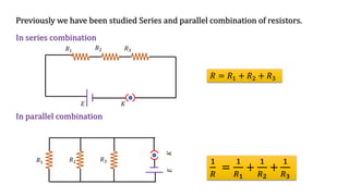

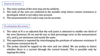

![A) To Compare emf of Cells
There are two methods to compare emf of cells.
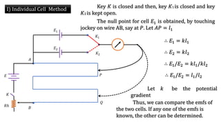
I] Direct Method/Individual Cell Method And
II] Sum and Difference Method](https://image.slidesharecdn.com/currentelectricity-230128124746-e7514844/85/Current-Electricity-pptx-24-320.jpg)
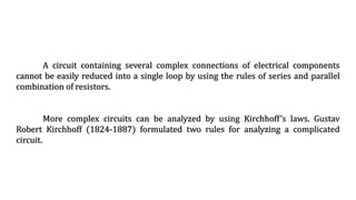
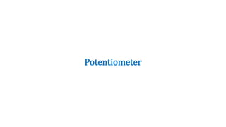
![As shown in the figure, potential 𝑉 is set up between
points 𝐴 and 𝐵 of a potentiometer wire. One end of a device is
connected to positive point A and the other end is connected to a
slider that can move along wire 𝐴𝐵. The voltage 𝑉 divides in
proportion of lengths 𝑙1 and 𝑙2 as shown in the figure.
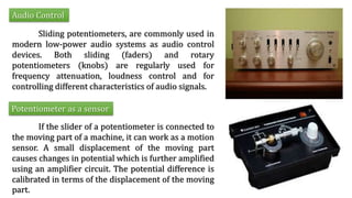
C] Applications of Potentiometer
Voltage Divider](https://image.slidesharecdn.com/currentelectricity-230128124746-e7514844/85/Current-Electricity-pptx-30-320.jpg)
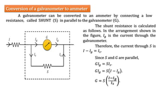
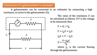
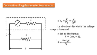
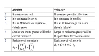

The document discusses various principles and laws related to current electricity, focusing on Kirchhoff's laws for analyzing complex circuits and the Wheatstone bridge for measuring resistances. It explains the applications of potentiometers and galvanometers in circuitry, including how to convert a galvanometer into an ammeter or voltmeter, emphasizing the importance of these devices in electrical measurements. Additionally, it addresses potential sources of errors and the advantages of potentiometers over traditional voltmeters.


![ppt current electricity -2developed [Autosaved] (1).pptx](https://cdn.slidesharecdn.com/ss_thumbnails/pptcurrentelectricity-2developedautosaved1-250724095217-f3899f3e-thumbnail.jpg?width=640&height=640&fit=bounds)


![potentiometer presentation slide [Autosaved].pptx](https://cdn.slidesharecdn.com/ss_thumbnails/potentiometerpresentationslideautosaved-240204142748-a5b488e5-thumbnail.jpg?width=640&height=640&fit=bounds)


