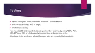
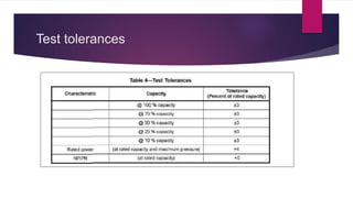
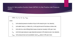
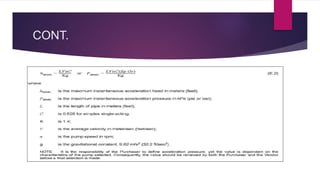
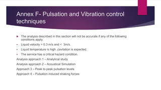
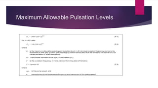
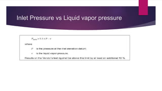
API 675 3rd Edition Over
view(Positive Displacement
Pumps Controlled Volume)
MAHENDRA PRABHU S
SENIOR ENGINEER - MECHANICAL
Scope
 Reciprocating and Controlled volume pumps
 Hydraulic diaphragm or packed plunger design
 Rotary Positive displacement pumps are not included
 Diaphragm Pumps that use direct mechanical actuation are excluded
Terms and Definitions
 Acceleration Pressure – Anticipated System Acceleration Pressure
The estimated Pressure Change due to changes in velocity in the piping system.
It is an important factor in the application of reciprocating pumps because of the
pulsating nature of the flow in the pump suction line, in addition to NPSHr, Vapor
pressure and pressure required to overcome suction line losses.
Controlled volume pump
A reciprocating Pump in which precise volume control is provided by varying effective
stroke length.
 These pumps are also known as proportioning, chemical injection, dosing or
metering pumps.
Cont.….
 Diaphragm Pump
A pump designed such that the process fluid is isolated from the plunger by means of
a hydraulically actuated flat or shaped diaphragm.
Displacement
Volume displaced per stroke. Displacement depends only on the physical dimensions of
the pumping element.
Net Positive Inlet Pressure (NPIP)
Minimum instantaneous pressure determined at the datum elevation (Under side of the
pump mounting plate) during pressure pulsations, Minus the vapor pressure of the fluid at
the maximum operating temperature and at any specified operating point.
Cont.….
 NPIPA- Net Positive Inlet Pressure Available determined by the Purchaser from
NPSHA and system design data including the acceleration losses.
 NPIPR – Net Positive Inlet Pressure Required determined by vendor including the
acceleration losses.
 Packed Plunger pump (or) Packed Piston Pump – The Process Fluid is in
direct contact with the Plunger.
 Volumetric efficiency - Ratio of the pump rated point flow to the total theoretical
displacement per unit time.
Pump Designations (Liquid End)
CONT.
Pump Designations (Drive End Pumps)
CONT.
Design
 Equipment shall be able to run at maximum rated input speed and relief valve
setting conditions simultaneously.
 The pump flow rate shall be adjustable over specified range of turndown ratio.
 Rated capacity shall be at least 110% of Maximum capacity specified.
 The steady state flow accuracy shall be with in plus or minus 1%.
 The Flow repeatability shall be with in Plus or Minus 3% at rated flow and
specified turn down ratio.
 Deviation from linearity shall not exceed Plus or Minus 3% of rated flow at
specified turn down ratio.
CONT.
 Suction and Discharge Check valves seats or cartridges shall field replaceable.
 If specified double check valves shall be furnished.
 Double diaphragm designs shall be provided with tapped hole connected to
conductivity probe in hydraulic type or Pressure type detector in dry design for
detecting diaphragm failure detection.
 Diaphragm pumps shall have an integral , adjustable hydraulic relief valve to
prevent failure of drive mechanism from excess discharge pressure.
 The relief valve setting pressure shall be 10% or 175 kPa (25 psi) above the rated
discharge pressure.
CONT.
 Packed Plunger pumps requires external relief valves at purchaser piping.
 Gears used in pump assembly shall be metal.
 Service factor shall be 1.5
 AGMA 6022 or AGMA 6013.
Capacity Adjustment
 Changing the actual or effective stroke length or stroking speed.
 Pump shall be capable of accepting manual or automatic stroke control
 Device used to change the capacity shall have visual indicator.
 Visual indicator shall have % of effective stroke length indication.
 Manual control shall be provided with positive locking device to retain capacity
setting.
Driver - Motors
 Motor power requirements less than 1 hp , motor specification shall be agreed
between Vendor and purchaser.
 Motor power above 1 hp – IEEE 841.
 The motor rating shall be at least 110% of the maximum power required.
 The motor rating shall be suitable for 100% of PLV accumulation pressure.
 PLV- Pressure Limiting valve.
Pressure Limiting Valves -PLV
 Positive displacement pumps shall be provided with pressure limiting valves or
other protective devices.
 PLV shall meet the requirements specified in API 520 or API 526.
Pulsation Suppression Devices
 Pulsation suppression devices are located in Suction and / or discharge.
 Three types of suppression devices are as follows.
 Volume bottles without internals.
 Pulsation dampeners using gas filled chamber isolated from pumped fluid by
piston or elastomeric diaphragm.
 Pulsation filters or attenuators and other proprietary designs based on acoustic
suppression techniques.
Testing
 Hydro stating test pressure shall be minimum 1.5 times MAWP
 But not less than 150 kPa or 20 psi.
 Performance testing
Flow repeatability and linearity tests are specified they shall run by using 100%, 75%,
50%, 25% and 10% of rated capacity in descending and ascending order.
Adjustable stroke length and adjustable speed tests are contected independently.
Test tolerances
Annex
 Annex A- Data Sheets
 Annex B - Materials
 Annex C – Inspector Check List
 Annex D – Controlled Volume Pumps vendor drawing and data requirements.
 Annex E- NPSH vs NPIP
 Annex F- Pulsation and Vibration control techniques
Annex E- Net positive Suction Head (NPSH) Vs Net Positive inlet Pressure
(NPIP)
CONT.
Annex F- Pulsation and Vibration control
techniques
 The analysis described in this section will not be accurate if any of the following
conditions apply.
 Liquid velocity > 0.3 m/s and < 3m/s.
 Liquid temperature is high ,cavitation is expected.
 The service has a critical hazard condition.
Analysis approach 1 – Analytical study
Analysis approach 2 – Acoustical Simulation
Approach 3 – Peak to peak pulsation levels
Approach 4 – Pulsation induced shaking forces
Maximum Allowable Pulsation Levels
Inlet Pressure vs Liquid vapor pressure

API 675 over view

  • 1.
    API 675 3rdEdition Over view(Positive Displacement Pumps Controlled Volume) MAHENDRA PRABHU S SENIOR ENGINEER - MECHANICAL
  • 2.
    Scope  Reciprocating andControlled volume pumps  Hydraulic diaphragm or packed plunger design  Rotary Positive displacement pumps are not included  Diaphragm Pumps that use direct mechanical actuation are excluded
  • 3.
    Terms and Definitions Acceleration Pressure – Anticipated System Acceleration Pressure The estimated Pressure Change due to changes in velocity in the piping system. It is an important factor in the application of reciprocating pumps because of the pulsating nature of the flow in the pump suction line, in addition to NPSHr, Vapor pressure and pressure required to overcome suction line losses. Controlled volume pump A reciprocating Pump in which precise volume control is provided by varying effective stroke length.  These pumps are also known as proportioning, chemical injection, dosing or metering pumps.
  • 4.
    Cont.….  Diaphragm Pump Apump designed such that the process fluid is isolated from the plunger by means of a hydraulically actuated flat or shaped diaphragm. Displacement Volume displaced per stroke. Displacement depends only on the physical dimensions of the pumping element. Net Positive Inlet Pressure (NPIP) Minimum instantaneous pressure determined at the datum elevation (Under side of the pump mounting plate) during pressure pulsations, Minus the vapor pressure of the fluid at the maximum operating temperature and at any specified operating point.
  • 5.
    Cont.….  NPIPA- NetPositive Inlet Pressure Available determined by the Purchaser from NPSHA and system design data including the acceleration losses.  NPIPR – Net Positive Inlet Pressure Required determined by vendor including the acceleration losses.  Packed Plunger pump (or) Packed Piston Pump – The Process Fluid is in direct contact with the Plunger.  Volumetric efficiency - Ratio of the pump rated point flow to the total theoretical displacement per unit time.
  • 6.
  • 7.
  • 8.
  • 9.
  • 10.
    Design  Equipment shallbe able to run at maximum rated input speed and relief valve setting conditions simultaneously.  The pump flow rate shall be adjustable over specified range of turndown ratio.  Rated capacity shall be at least 110% of Maximum capacity specified.  The steady state flow accuracy shall be with in plus or minus 1%.  The Flow repeatability shall be with in Plus or Minus 3% at rated flow and specified turn down ratio.  Deviation from linearity shall not exceed Plus or Minus 3% of rated flow at specified turn down ratio.
  • 11.
    CONT.  Suction andDischarge Check valves seats or cartridges shall field replaceable.  If specified double check valves shall be furnished.  Double diaphragm designs shall be provided with tapped hole connected to conductivity probe in hydraulic type or Pressure type detector in dry design for detecting diaphragm failure detection.  Diaphragm pumps shall have an integral , adjustable hydraulic relief valve to prevent failure of drive mechanism from excess discharge pressure.  The relief valve setting pressure shall be 10% or 175 kPa (25 psi) above the rated discharge pressure.
  • 12.
    CONT.  Packed Plungerpumps requires external relief valves at purchaser piping.  Gears used in pump assembly shall be metal.  Service factor shall be 1.5  AGMA 6022 or AGMA 6013.
  • 13.
    Capacity Adjustment  Changingthe actual or effective stroke length or stroking speed.  Pump shall be capable of accepting manual or automatic stroke control  Device used to change the capacity shall have visual indicator.  Visual indicator shall have % of effective stroke length indication.  Manual control shall be provided with positive locking device to retain capacity setting.
  • 14.
    Driver - Motors Motor power requirements less than 1 hp , motor specification shall be agreed between Vendor and purchaser.  Motor power above 1 hp – IEEE 841.  The motor rating shall be at least 110% of the maximum power required.  The motor rating shall be suitable for 100% of PLV accumulation pressure.  PLV- Pressure Limiting valve.
  • 15.
    Pressure Limiting Valves-PLV  Positive displacement pumps shall be provided with pressure limiting valves or other protective devices.  PLV shall meet the requirements specified in API 520 or API 526.
  • 16.
    Pulsation Suppression Devices Pulsation suppression devices are located in Suction and / or discharge.  Three types of suppression devices are as follows.  Volume bottles without internals.  Pulsation dampeners using gas filled chamber isolated from pumped fluid by piston or elastomeric diaphragm.  Pulsation filters or attenuators and other proprietary designs based on acoustic suppression techniques.
  • 17.
    Testing  Hydro statingtest pressure shall be minimum 1.5 times MAWP  But not less than 150 kPa or 20 psi.  Performance testing Flow repeatability and linearity tests are specified they shall run by using 100%, 75%, 50%, 25% and 10% of rated capacity in descending and ascending order. Adjustable stroke length and adjustable speed tests are contected independently.
  • 18.
  • 19.
    Annex  Annex A-Data Sheets  Annex B - Materials  Annex C – Inspector Check List  Annex D – Controlled Volume Pumps vendor drawing and data requirements.  Annex E- NPSH vs NPIP  Annex F- Pulsation and Vibration control techniques
  • 20.
    Annex E- Netpositive Suction Head (NPSH) Vs Net Positive inlet Pressure (NPIP)
  • 21.
  • 22.
    Annex F- Pulsationand Vibration control techniques  The analysis described in this section will not be accurate if any of the following conditions apply.  Liquid velocity > 0.3 m/s and < 3m/s.  Liquid temperature is high ,cavitation is expected.  The service has a critical hazard condition. Analysis approach 1 – Analytical study Analysis approach 2 – Acoustical Simulation Approach 3 – Peak to peak pulsation levels Approach 4 – Pulsation induced shaking forces
  • 23.
  • 24.
    Inlet Pressure vsLiquid vapor pressure