Download to read offline


![254 VIBRATION PROBLEMS IN ENGINEERING
Adding these equations together we get
n<f>n
= 0, (tt
which means that the moment of momentum of the system about the
axis of the shaft remains constant during the free vibration. In the fol-
lowing this moiftent of momentum will be taken equal to zero. In this
manner any rotation of the shaft as a rigid body will be excluded and only
vibratory motion due to twist of the shaft will be considered. To find the
frequencies of the natural vibrations of this system we proceed as before
and take the solutions of equations (a) in the form
<?1
= Xi COS pt, <P2
= X2 COS ptj
Substituting in equations (a) we obtain
= Xa cos
- X2 )
=
- X2 )
- A; 2 (X2
- X3 )
=
fcn_l(X n -l ~ X w)
= 0. (c)
Eliminating Xi, X2 ,
from
these equations, we obtain an equation
of the nth degree in p
2
called the fre-
quency equation. The n roots of this
equation give us the n frequencies cor-
VM4
^mjj]j| j
x3 responding to the n principal modes of
vibration of the system.
The System of Three Discs. Let
us apply the above given general dis-
cussion to the problem of three discs,
Fig. 148. The system of equations (c)
in this case becomes:
- fci(Xi
- X2)
=
+ fci(Xi
- X2)
- /b 2 (X2
- X3 )
=
/3X3 p
2
+ fc 2 (X2
- Xs)
= 0.
From the. first and the third of these equations we find that :
FIG. 148.
X3
=-](https://image.slidesharecdn.com/timoshenko-vibrationproblemsinengineeringe-bookpart-2-200710113836/85/Timoshenko-Vibration-Problems-in-Engineering-E-book-Part-2-3-320.jpg)


![268 VIBRATION PROBLEMS IN ENGINEERING
oscillation must be equal to the energy absorbed at the damping point.
In this manner we obtain
2* 2r
/P
d<f> m d<p m f
'
,*,.C
~~^T ~^7 * = / Mt cos pt~dt,
at at J$ at
or substituting
<Pm
= X m Sin pt] <p n
= Xn SU1 pt,
we obtain
M Xn
Xm = , (e)
cp X m
and the amplitude of vibration for the first mass will be
Knowing the damping constant c and taking the ratios Xn/X m and Xi/X m
from the normal elastic curve (see Fig. 151) the amplitudes of forced vibra-
tion may be calculated for the case of a simple harmonic torque with damp-
ing applied at a certain section of the shaft.
Consider again the example of the four discs shown in Fig. 152. By
using the method of successive approximation we shall find with sufficient
accuracy that the circular frequency of the lowest mode of vibration is
approximately p = 235 radians per second, and that the ratios of the
amplitudes for this mode of vibration are X2/Xi
= 0.752, Xs/Xi = 1.33,
X4/Xi = 1.66. The corresponding normal elastic curve is shown in
Fig. 1526. Assume now that the periodic torque M cos pt is applied at
the first disc and that the damping is applied at the fourth disc.* Then
from equation (/)
x = ^
Cp X4 X4
Substituting the value from the normal elastic curve for the ratio
Xi/X4 we find
Xi-0.38
'
cp
From this equation the amplitude Xi can be calculated for any given torque
Mt and any given value of damping factor c.
* The same reasoning holds if damping is applied to any other disc.](https://image.slidesharecdn.com/timoshenko-vibrationproblemsinengineeringe-bookpart-2-200710113836/85/Timoshenko-Vibration-Problems-in-Engineering-E-book-Part-2-17-320.jpg)


![276 VIBRATION PROBLEMS IN ENGINEERING
In calculating the amount of energy dissipated per cycle we note that the two shaded
areas in Fig. 156a are equal. Hence
^r
/
JQ
E = M/(wh
- <*f)dt
= 2
Q
or, substituting from (6) and (c),
# = 2M/
~+/2r jj/Y]
/ Xo> cos w(* *o)
--~ dt.
J-*/*<* L l J
Performing the integration we obtain
E = 4A//X cos wto,
or by using (d) we find the final expression for the amount of energy dissipated per cycle:
By a change in the adjustable nuts d the friction torque M/ can be properly chosen.
If the force exerted by the loading springs is very small the friction force is also small and
its damping effect on the torsional vibrations of the crankshaft will be negligible. By
tightening up the nuts we can get another extreme case when the friction torque is so
large that the flywheel does not slide at all and no dissipation of energy takes place.
The most effective damping action is obtained when the friction torque has the magni-
tude at which expression (e) becomes a maximum. Taking the derivative of this expres-
sion with respect to M/ and equating it to zero we find the most favorable value for the
torque
A/2
Mf = -* A 2
/. (/)
With this value substituted in (e) the energy dissipated per cycle becomes
Having this expression we may calculate the amplitude of the forced vibration at
resonance in the same manner as in the case of a viscous damping acting on one of the
vibrating discs (see p. 268). If a pulsating torque M cos a>(t to) is acting on a disc of
which the amplitude of torsional vibration is Xm,
the work done by this torque per
cycle is (see p. 45) MXm7r. Equating this work to the energy dissipated (g) we find
The ratio Xn/X can be taken from the normal elastic curve of the vibrating shaft so
that if M and I are given the amplitude X can be calculated from equation (h). Usually
equation (h) may be applied for determining the necessary moment of inertia / of the
damper. In such a case the amplitude X should be taken of such a magnitude as to have
the maximum torsional stress in the shaft below the allowable stress for the material of
the shaft. Then the corresponding value of / may be calculated from equation (h).](https://image.slidesharecdn.com/timoshenko-vibrationproblemsinengineeringe-bookpart-2-200710113836/85/Timoshenko-Vibration-Problems-in-Engineering-E-book-Part-2-25-320.jpg)


![TORSIONAL AND LATERAL VIBRATION OF SHAFTS 281
as the equations of statics. It is only necessary to add to the loads acting
on the shaft the inertia forces. Denoting as before, by y and t/2 the deflec-
tions of the shaft from the position of equilibrium under the loads W
and W2, respectively, the inertia forces will be (W/g)yi and (WVfiOife.
'These inertia forces must be in equilibrium with the elastic forces due to
the additional deflection and two equations equivalent to (a) and (6) can
be written down as follows.
Wi .. . W* ..
= - a
9
, Wi .. W2 ..
2/2
= ~ o -
?/i
- c 2/2-
9 Q
Assuming, as before,
2/i
= Xi cos pt] 7/2
= ^2 cos pty
and substituting in eqs. (I) we obtain,
9
(0
Wi
9
On)
Putting the determinant of these two equations equal to zero, the fre-
quency equation (A-), which we had before, will be obtained.
Hf
Fia. 160.
The methods developed above for calculating the frequencies of the
lateral vibrations can be used also in cases where the number of discs or
the number of spans is greater than two. Take, for instance, the case
shown in Fig. 160. By using a method analogous to the one employed
in the previous example, the statical deflections of the shaft under the
discs can be represented in the following form :
63 =
+ CL22W2 + 023TF3,
+ 032^2 +](https://image.slidesharecdn.com/timoshenko-vibrationproblemsinengineeringe-bookpart-2-200710113836/85/Timoshenko-Vibration-Problems-in-Engineering-E-book-Part-2-30-320.jpg)
![282 VIBRATION PROBLEMS IN ENGINEERING
in which an, 012, . - are constants depending on the distances between
the supports, the distances of the discs from the supports and on the
flexural rigidity of the shaft. From the reciprocal theorem it can be
concluded at once that ai2 = 021, ais = asi and am = 032. Applying
now D'Alembert's principle and denoting by yi, y2 and ys the displace-
ments of the discs during vibration from the position of equilibrium, the
following equations of vibration will be derived from the statical equa-
tions (n).
Wi .. W2 .. W3 ..
2/1
= an 2/1 ai2 2/2 ais 2/3,
9 9 9
Wi .. W2 .. Wz ..
i/2
= a2 i i/i 022 2/2 #23 2/3,
999Wi .. W2 .. W3 ..
2/3
= #31 2/1 #32 2/2 33 2/3,
999from which the frequency equation, a cubic in p
2
,
can be gotten in the
usual manner. The three roots of this equation will give the frequencies
of the three principal modes of vibration of the system under considera-
tion.*
It should be noted that the frequency equations for the lateral vibra-
tions of shafts can be used also for calculating critical speeds of rotation.
A critical speed of rotation is a speed at which the centrifugal forces of the
rotating masses are sufficiently large to keep the shaft in a bent condition
(see Art. 17). Take again the case of two discs (Fig. 155a) and assume
that 2/1 and y2 are the deflections, produced by the centrifugal forces |
(Wi/g)<*>
2
yi and (W2 /g)u'
2
y2 of the rotating discs. Such deflections can
exist only if the centrifugal forces satisfy the following conditions of equi-
librium [see eqs. (a) and (6)],
Wi 2 ,
W2
2
2/i
= an CO^T/I + a !2 u2
y%,
9 9
Wi W2
^
2/2
= 2i w2
2/i + 022 a>
2
i/2.
9 9
These equations can give for y and 2/2 solutions different from zero only
in the case when their determinant vanishes. Observing that the equa-
*
A graphical method of solution of frequency equations has been developed by
C. R. Soderberg, Phil. Mag., Vol. 5, 1928, p. 47.
f The effect of the weight of the shaft on the critical speeds will be considered later.](https://image.slidesharecdn.com/timoshenko-vibrationproblemsinengineeringe-bookpart-2-200710113836/85/Timoshenko-Vibration-Problems-in-Engineering-E-book-Part-2-31-320.jpg)
![TORSIONAL AND LATERAL VIBRATION OF SHAFTS 283
tions (o) are identical with the equations (m) above and equating their
determinant to zero, an equation identical with eq. (fc) will be obtained for
calculating the critical speeds of rotation.
Graphical Method. In the case of shafts of variable cross section or
those having many discs the analytical method of calculating the critical
speeds, described above, becomes very complicated and recourse should
be made to graphical methods. As a simple example, a shaft supported
at the ends will now be considered (Fig. 62). Assume some initial deflection
of the rotating shaft satisfying the end conditions where t/i, 3/2, . . . are
the deflections at the discs W, W2, ... If be the angular velocity then
the corresponding centrifugal forces will be (Wi/g)u
2
yi, (W2/g)u
2
y2, . .
Considering these forces as statically applied to the shaft, the corre-
sponding deflection curve can be obtained graphically as was explained in
Art. 17. If our assumption about the shape of the initial deflection curve
was correct, the deflections y ', 7/2', ., as obtained graphically, should be
proportional to the deflections 2/1, 2/2, ... initially assumed, and the critical
speed will be found from the equation
(90)
This can be explained in the following manner.
By taking ucr as given by (90) instead of w, in calculating the cen-
trifugal forces as above, all these forces will increase in the ratio y/yi]
the deflections graphically derived will now also increase in the same
proportion and the deflection curve, as obtained graphically, will 'now
coincide with the initially assumed deflection curve. This means that
at a speed given by eq. (90), the centrifugal forces are sufficient to keep the
rotating shaft in a deflected form. Such a speed is called a critical speed
(see p. 282).
It was assumed in the previous discussion that the deflection curve, as
obtained graphically, had deflections proportional to those of the curve
initially taken. If there is a considerable difference in the shape of these
two curves and a closer approximation for wcr is desired, the construction
described above should be repeated by taking the deflection curve, obtained
graphically, as the initial deflection curve.*
The case of a shaft on three supports and having one disc on each span
(Fig. 157) will now be considered. In the solution of this problem we may
*
It was pointed out in considering Rayleigh's method (see Art. 16), that a con-
siderable error in the shape of the assumed deflection curve produces only a small effect
on the magnitude of wcr provided the conditions at the ends are satisfied.](https://image.slidesharecdn.com/timoshenko-vibrationproblemsinengineeringe-bookpart-2-200710113836/85/Timoshenko-Vibration-Problems-in-Engineering-E-book-Part-2-32-320.jpg)


![TORSIONAL AND LATERAL VIBRATION OF SHAFTS 297
The four equations (v) and (w) completely describe the free vibrations
of a rigid rotor on flexible pedestals. Substituting in these equations
i/i
= A sin pt 1/2
= B sin pi; z = C cos pi] z<2
= D cos pt,
four homogeneous linear equations in A, B, C, and D will be obtained.
Equating the determinant of these equations to zero, we get the frequency
equation from which the frequencies of the four natural modes of vibra-
tion of the rotor can be calculated.
Consider now a forced vibration of the rotor produced by some eccen-
trically attached mass. The effect of such an unbalance will be equivalent
to the action of a disturbing force with the components
Y = A cos co; Z = B sin ut,
applied to the center of gravity and to a couple with the components,
My = C sin cot ;
Mz
= D cos w.
Instead of the eqs. (v) and (w) we obtain
W
ky + 1^2) + ciyi + c2?/2 =A cos at,
gi
w
~T ('221 + h'z2) + dizi + d<2Z2
= B sin wt,
gi
(a')
~~
21 , 7 j i t n j
zidih + C sin at,
I
1J2 yi 7 , i , rk j
h 11
-;
= yzczlz + yicih + D cos ut.
I i
The particular solution of these equations representing the forced
vibration of the rotor will be of the form
y
= A' cos ut; y<2
= B1
cos ut ; z = C' sin co; 22 = -D' sin ut.
Substituting in eqs. (a)', tiie amplitude of the forced vibration will be
found. During this vibration the axis of the rotor describes a surface
given by the equations
y = (a + bx) cos ut,
z = (c + dx) sin ut,](https://image.slidesharecdn.com/timoshenko-vibrationproblemsinengineeringe-bookpart-2-200710113836/85/Timoshenko-Vibration-Problems-in-Engineering-E-book-Part-2-46-320.jpg)


![300 VIBRATION PROBLEMS IN ENGINEERING
<p
= the angle of rotation of the disc equal to the angle between the radius
SC and x axis.
= the angle of rotation of the vertical plane OC.
l/
= the angle of rotation of the disc with respect to the plane OC.
Then <p
= ^ + 6. The coordinates x and y of the center of gravity C
and the angle of rotation <p will be taken as coordinates determining the
position of the disc in the plane xy.
The differential equations of motion of the center of gravity C can
easily be written in the usual way if we note that only one force, the
elastic reaction of the shaft, is acting on the disc in the xy plane. This
force is proportional to the deflection OS of the shaft and its components
in the x and y directions, proportional to the coordinates of the point S, will
be k(x e cos <p) and k(y e sin <p) respectively. Then the differ-
ential equations of motion of the center C will be
mx = k(x e cos <p) ; my = k(y e sin <p)
or
mx + kx = ke cos <p,
(a)
my + ky = ke sin <p.
The third equation will be obtained by using the principle of angular
momentum. The angular momentum of the disc about the axis con-
sists (1) of the angular momentum mi2
# of the disc rotating with the
angular velocity about its center of gravity and (2) of the angular
momentum m(xy yx) of the mass m of the disc concentrated at its
center of gravity. Then the principle of angular momentum gives the
equation
-
mi
2
v + m(xy y%) }
= M,
at
or
mi2
'<p + m(xy yx)
= M, (6)
in which M is the torque transmitted to the disc by the shaft.
The equations (a) and (6) completely describe the motion of the disc.
When M = a particular solution of the equations (a) and (6) will be
obtained by assuming that the center of gravity C of the disc remains in
the plane OS of the deflection curve of the shaft and describes while rotating
at constant angular velocity
= w, a circle of radius r. Then substituting
in equations (a) x = r cos ut] y = r sin ut and taking <p
= ut for the case](https://image.slidesharecdn.com/timoshenko-vibrationproblemsinengineeringe-bookpart-2-200710113836/85/Timoshenko-Vibration-Problems-in-Engineering-E-book-Part-2-49-320.jpg)


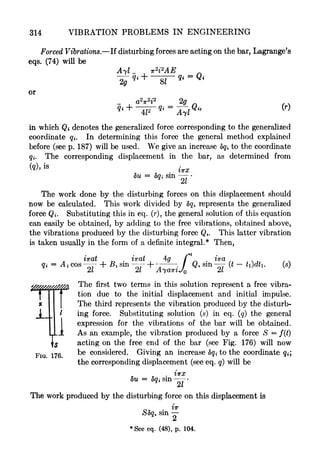
![VIBRATIONS OF ELASTIC BODIES 313
This result coincides completely with what was obtained before (see eq. e).
We see that the equations (p) contain each only one coordinate #. The
chosen coordinates are independent of each other and the corresponding
vibrations are "principal" modes of vibration of the bar (see p. 197).
The application of generalized coordinates is especially useful in the dis-
cussion of forced vibrations. As an example, let us consider here the case of
a bar with one end built in and another end free. The solution for this
case can be obtained at once from expression (99). It is only necessary to
assume in the previous case that the bar with free ends performs vibrations
symmetrical about the middle of the bar. This condition will be satisfied
by taking i = 1, 3, 5 in solution (99). Then the middle section can
be considered as fixed and each half of the bar will be exactly in the same
condition as a bar with one end fixed and another free. Denoting by /
the length of such a bar and putting the origin of coordinates at the fixed
end, the solution for this case will be obtained by substituting 21 for I and
sin iirx/21 for cos iirx/l in eq. (99). In this manner we obtain
.
.
n . ,+ *^
u = 2^ sm l^cos + B,sin ] (100)
<- 1,3,5,.-.
Al M Ll /
Now, if we consider the expressions in the brackets of the above solu-
tion as generalized coordinates and use the symbols <?
for them, we obtain,
*" / j f "*"
07 W/
4-1,3,5,... ^
Substituting this in the expressions for the potential and kinetic energy
we obtain :
AE
E it. (102)
1,3,5,..-
Lagrange's equation for free vibration corresponding to any coordinate
ji will be as follows:
from which
iwat ,
_ .
iirat
Aicos- -
+ Bism -
This coincides with what we had before (see eq. (100)).](https://image.slidesharecdn.com/timoshenko-vibrationproblemsinengineeringe-bookpart-2-200710113836/85/Timoshenko-Vibration-Problems-in-Engineering-E-book-Part-2-62-320.jpg)


![VIBRATIONS OF ELASTIC BODIES 327
The constants C and D should be determined in such a manner as to
satisfy the end conditions. Substituting (d) in eqs. (a) and (6) we obtain
p* (ccos
Pl
+ D sin ?l
] I2 = P
GIP (- Csin^ + Dcos^Y (e)
a a / a a a I
Eliminating the constants C and D the following frequency equation
will be obtained,
/ pi pali . pl p / pi pali pl ...
p
2
lcos - -sin- 1/2=-' G/p (sm-+ cos~J- (/)
a GIP a/ a a GIP a/
Letting
pl a Iig II /2 / - = 0;
-
= - = m; T = n> (d
a ytlp /o /o
where 7o = (yU r /g) is the moment of inertia of the shaft about its axis,
we obtain, from eq. (/) the frequency equation in the following form:
pn(l
- m/3 tan jS)
= (tan ft + m$)
or
tan^ =
^-^. (112)
mn@2
1
Let
01, 02, 03,
'
be the consecutive roots of this transcendental equation, then the corre-
sponding normal functions, from (d) and (e) will be
v n ( &x o ^A = C I cos -- mpi sin I
and we obtain for the general solution in this case
* ^f ^ a ^V^ ^^_LPo = 2_j
cos
~7
m^ sm ~T / 1
cos
T" "^ * sm
If the moments of inertia /i and /2 of the discs are small in comparison
with the moment of inertia /o of the shaft, the quantities m and n in eq.
112 become small, the consecutive roots of this equation will approach
the values TT, 2?r, and the general solution (113) approaches the solution
(111) given above for a shaft with free ends.](https://image.slidesharecdn.com/timoshenko-vibrationproblemsinengineeringe-bookpart-2-200710113836/85/Timoshenko-Vibration-Problems-in-Engineering-E-book-Part-2-76-320.jpg)


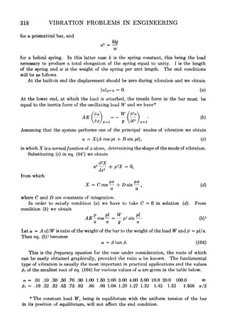
![338 VIBRATION PROBLEMS IN ENGINEERING
From the elementary theory of bending we have for bending moment and shearing force
the following equations,
M = - El ; Q = k'pAG = k' (
- * ) AG,
dx dx I
In which k
f
is a numerical factor depending on the shape of the cross section; A is the
cross sectional area and G is modulus of elasticity in shear. The differential equation
of rotation of an element mnmn (Fig. 179) will be
dM j ,
^ d * 7
dx + Qdx = dx.
dx g dt2
Substituting (6) we obtain
dx'2
dx I g dt'
2
The differential equation for the translatory motion of the same element in a vertical
direction will be
dQ yA Vy
dx = dx,
dx g dt'
2
or
.. .
- - }AG = 0. (d)
g dt* dx'
2
dx/
'
Eliminating fy from equations (c) and (d) the following more complete differential
equation for the lateral vibration of prismatical bars will be obtained
_ ..- .
dx* g dt'
2
g
^
gk'G] dx'W g gk'G dt*
The application of this equation in calculating the frequencies will be shown in the
following article.
66. Free Vibration of a Bar with Hinged Ends. General Solution.
In considering particular cases of vibration it is useful to present the
general solution (127) in the following form
X = Ci(cos kx + cosh kx) + 2 (cos kx cosh kx)
+ Ca(sin kx + sinh kx) + C^sin kx sinh kx)
-
.
(140)
In the case of hinged ends the end conditions are
(1) (X),. = 0; (2) (ff) =0;
rfx
2
/ z _
(3) (Z),.,-0; (4) =0. (a)](https://image.slidesharecdn.com/timoshenko-vibrationproblemsinengineeringe-bookpart-2-200710113836/85/Timoshenko-Vibration-Problems-in-Engineering-E-book-Part-2-87-320.jpg)


![362 VIBRATION PROBLEMS IN ENGINEERING
Ibs., the additional deflection, calculated from eq. (161), will be
(2i
3
/EIir
4
) (300,000). Adding this to the statical deflection, calculated
above for the case of the locomotive approaching the end of the bridge, we
obtain for the complete deflection at the center (2P/EIw*) (506,000).
Comparing this with the maximum statical central deflection (ZP/EIir
4
)
X (275,000), given above, it can be concluded that the increase in deflec-
tion due to impact is in this case about 84 per cent. Assuming the number
of revolutions n equal to 6 (the diameter of driving wheels equal to 6J^
feet) and assuming again a condition of resonance, we will obtain for the
same numerical example an increase in deflection equal to 56 per cent.
In the case of bridges of shorter spans, when the frequency of natural
vibration is considerably larger than the number of revolutions per second
of the driving wheels, a satisfactory approximation can be obtained by
taking only the first term in the series (157) and assuming the most un-
favorable condition, namely, that sin ([irv/l] + co) and sin ([wv/l] o>)
become equal to 1 and sin ir'
2
at/l
2
equal to 1 at the moment t = l/2v
when the pulsating force arrives at the middle of the spun. Then the
additional deflection, from (157), will be
1
.
*
,
<*
,
l-(/3+a)
2
l-(/3-a)
2
(l-0)
2
-a2
"*
2PP 1 - a (162)
Consider, for instance, a 60-foot span bridge and assume the same
kind of loading as in the previous example, then the maximum statical
deflection is (2l
3
/EIw
4
) (173,000) approximately. If the driving wheels
have a circumference of 20 feet and make 6 revolutions per second, the
maximum downwards force on the girder will be 18,750(6/5)
2 = 27,000
Ibs. Assuming the natural frequency of the bridge equal to 9, we obtain
from eq. (153)
2/3 9Z3
5 = (27>
000 x 2' 5?)
Hence,
dynamical deflection 173 + 69.4 ^ ^--_. --- _..
i 4Qt
statical deflection 173
The impact effect of the balancing weights in this case amounts to 40
per cent.](https://image.slidesharecdn.com/timoshenko-vibrationproblemsinengineeringe-bookpart-2-200710113836/85/Timoshenko-Vibration-Problems-in-Engineering-E-book-Part-2-111-320.jpg)


![VIBRATIONS OF ELASTIC BODIES 381
Other Cases of Vibration of a Cantilever of Variable Cross Section. In
the general case the frequency of the lateral vibrations of a cantilever can
be represented by the equation
in which i is radius of gyration of the built-in section,
I is length of the cantilever,
a is constant depending on the shape of the bar and on the mode
of vibration.
In the following the values of this constant a for certain particular
cases of practical importance are given.
1. If the variations of the cross sectional area and of the moment of
inertia, along the axis a-, can be expressed in the form,
A = axm
]
I = bxm
, (183)
x being measured from the free end, i remains constant along the length
of the cantilever and the constant a, in eq. (182) can be represented for
the fundamental mode with sufficient accuracy by the equation
*
a = 3.47(1 + 1.05ra).
2. If the variation of the cross sectional area and of the moment of
inertia along the axis x can be expressed in the form
(184)
x being measured from the built-in end, then i remains constant along the
length of the rod and the quantity a, in eq. (182), will be as given in the
table below. f
c = .4 .6 .8 1.0
a =3. 515 4.098 4.585 5.398 7.16
Bar of Variable, Cross Section with Free Ends. Let us consider now the
case of a laterally vibrating free-free bar consisting of two equal halves
*
See Akimasa Ono, Journal of the Society of Mechanical Engineers, Tokyo, Vol.
27 (1924), p. 467.
t Akimasa Ono, Journal of the Society of Mechanical Engineers, Vol. 28 (1925), p.
429.](https://image.slidesharecdn.com/timoshenko-vibrationproblemsinengineeringe-bookpart-2-200710113836/85/Timoshenko-Vibration-Problems-in-Engineering-E-book-Part-2-130-320.jpg)


![388 VIBRATION PROBLEMS IN ENGINEERING
It should be noted that the blades are usually connected in groups by
means of shrouding wires. These wires do not always substantially
affect the frequencies of the axial vibrations but they may change the
frequencies of the tangential vibrations considerably.*
65. Vibration of Hulls of Ships. As another example of the application
of the theory of vibration of bars of variable section, the problem of the
vibration of the hull of a ship will now be considered. The disturbing
force in this case is usually due to unbalance in the engine or to the action
of propellersf and, if the frequency of the disturbing force coincides with
the frequency of one of the natural modes of vibration of the hull, large
forced vibrations may be produced. If the hull of the ship be taken as a
bar of variable section with free ends and Ritz's method (see Art. 62) be
applied, the frequencies of the various modes can always be calculated with
sufficient accuracy from the eqs. (178).
To simplify the problem let us assume that the bar is symmetrical
with respect to the middle cross section and that, by putting the origin of
coordinates in this section, the cross sectional area and moment of inertia
for any cross section can be represented, respectively, by the equations
A = Ao(l
- ex2
)] I = J (l
- 6z2
), (a)
in which AQ and 7o denote the cross sectional area and the moment of
inertia of the middle cross section, respectively. It is understood that x
may vary from x = I to x = +1,21 being the length of the ship.
We will further assume that the deflection during vibration may be
represented by
y = X cos pt,
in which X is taken in the form of the series,
X = ai<pi(x) + a<2,<p2(x) + d3<f>z(x) + .
(6)
We must choose for <pi, <p2 ,
suitable functions, satisfying the end
conditions. The ratios between the coefficients a 9 #2, 03 and the
frequencies will be then obtained from the equations (178).
*
See Stodola's book, loc. cit. p. 277. See also W. Hort, V. D. I. Vol. 70 (1926),
p. 1422, E. Schwerin, Uber die Eigenfrequenzen der Schaufelgruppen von Dampftur-
binen, Zeitschr. f. techn. Physik, Vol. 8, 1927, p. 312, and R. P. Kroon, Trans. Am. Soc.
Mech. Engrs., V. 56, p. 109, 1934.
f Propeller Vibration is discussed in the paper by F. M. Lewis presented before the
"
Society of Naval Architects and Marine Engineers," November, 1935, New York.](https://image.slidesharecdn.com/timoshenko-vibrationproblemsinengineeringe-bookpart-2-200710113836/85/Timoshenko-Vibration-Problems-in-Engineering-E-book-Part-2-137-320.jpg)

![390 VIBRATION PROBLEMS IN ENGINEERING
Taking the normal functions, obtained in this manner, as suitable
functions <p(x) in the series (6) we obtain
~, 1 cos k%x cosh k%l + cosh k2X cos k%l , .
X = ai TT-- + a2 , 1
.
(0)
V 2 V cos2
fc 2Z + cosh2
k2l
Substituting the above in eq. (178), we obtain
a f f
+l
^ ^ , fJ
1
/o / (1 bx2
) / J / j
ala] (pi <f>j
ax
dan [ J-i 1=1.2.3^-1.2.3
!(i ,_J2) ^.^efai.o
<-l. 2. 3, ... >1. 2. 3. ... J
and denoting
/ /
J i
* *; '
</_ ^
* ; t;
we obtain, from (A),
I] a% (ain
- X^in)
= 0, (0
<-l,2,3,...
in which
x -
W' w
For determining the fundamental mode of vibration two terms of
the series (g) are practically sufficient. The equations (I) in this case
become
ftn) + &2(<*21 X/32 i)
= 0,
i(ai2 X/3i 2) + 02(0:22 Xfe) = 0. (n)
In our case,
.. _ cos k2X cosh kzl + cosh fc2x cos fc 2t
^>i
= 0; ^2
" = fc2
2
/
Vcos2
k%l + cosh2
k%l
Substituting this in (fc) and performing the integration, we obtain
<*ii
= 0; ai2 = 0; 2i = 0,
/
+l
^1 98
(1
- 6z2
)(v>2")
2
^ = ^(1
- .0876Z2
), (p)
*
^u = 1(1
- .333cZ2
); /3 12 = /321 = .297d3
; /322 = 1(1
- .481cZ2
). (g)](https://image.slidesharecdn.com/timoshenko-vibrationproblemsinengineeringe-bookpart-2-200710113836/85/Timoshenko-Vibration-Problems-in-Engineering-E-book-Part-2-139-320.jpg)


![VIBRATIONS OF ELASTIC BODIES 413
and of the corresponding velocities, hence the coordinates chosen are prin-
cipal coordinates and the corresponding vibrations are normal modes of
vibration of the membrane.
The differential equation of a normal vibration, from (d) and (e), will be
w ab .. abw2
/m2
n2
g 4 4 a2
from which,
The lowest mode of vibration will be obtained by putting m = n = 1.
Then
The deflection surface of the membrane in this case is
TTX TT]j
v = C sin sin ~-
(g)
In the same manner the higher modes of vibration can be obtained.
Take, for instance, the case of a square membrane, when a = b. The
frequency of the lowest tone is
'
(205)
-
aV2
The frequency is directly proportional to the square root of the tension S
and inversely proportional to the length of sides of the membrane and to
the square root of the load per unit area.
The next two higher modes of vibration will be obtained by taking
one of the numbers ra, n equal to 2 and the other to 1. These two modes
have the same frequency, but show different shapes of deflection surface.
In Fig. 201, a and b the node lines of these two modes of vibration are
shown. Because of the fact that the frequencies are the same it is possible
to superimpose these two surfaces on each other in any ratio of their
maximum deflections. Such a combination is expressed by
/ . 2irx . try .
TTX .
2iry
v = I C sin -- sin --h D sin sin - I
,
a a a a /](https://image.slidesharecdn.com/timoshenko-vibrationproblemsinengineeringe-bookpart-2-200710113836/85/Timoshenko-Vibration-Problems-in-Engineering-E-book-Part-2-162-320.jpg)


![424 VIBRATION PROBLEMS IN ENGINEERING
From this the frequencies of the lowest mode and of the higher modes of
vibration can be easily calculated. Taking, for instance, a square plate
we obtain for the lowest mode of vibration
rH
(215)
In considering higher modes of vibration and their nodal lines, the dis-
cussion previously given for the vibration of a rectangular membrane can
be used. Also the case of forced vibrations of a rectangular plate with
simply supported edges can be solved without any difficulty. It should
be noted that the cases of vibration of a rectangular plate, of which two
opposite edges are supported while the other two edges are free or clamped,
can also be solved without great mathematical difficulty.
*
The problems of the vibration of a rectangular plate, of which all the
edges are free or clamped, are, however, much more complicated. For
the solution of these problems, Ritz' method has been found to be very
useful, f In using this method we assume
v = VQ cos pty (e)
where VQ is a function of x and y which determines the mode of vibration.
Substituting (e) in the equations (210) and (211), the following expressions
for the maximum potential and kinetic energy of vibration will be obtained :
p
2
I I v
2
dxdy,
^lj- -
+ 2(1 v)
-- ] dxdy
dx2
dy
2 ^ '
dxdy/
J
-r
J J ^
from which
Now we take the function VQ in the form of a series
vo = ai<t>i(x, y) + d2<p2(x, y) H----
, (f)
*
See Voigt, Gottinger Nachrichten, 1893, p. 225.
t See W. Ritz, Annalen der Physik, Vol. 28 (1909), p. 737. See also "Gesammelte
Werke" (1911), p. 265.](https://image.slidesharecdn.com/timoshenko-vibrationproblemsinengineeringe-bookpart-2-200710113836/85/Timoshenko-Vibration-Problems-in-Engineering-E-book-Part-2-173-320.jpg)


This document discusses methods for calculating the natural frequencies of torsional vibration in shafts with multiple rotating masses. It first presents the general differential equations of motion for a shaft with n rotating masses connected by spring-like sections. Solving these equations yields a frequency equation with n roots, corresponding to the n natural frequencies of the system. It then applies this approach to specific examples, such as a shaft with three discs. The natural frequencies are calculated from a cubic frequency equation. Approximate methods are also described to estimate the lowest frequencies in more complex systems by treating them as simpler subsystems.


![Bujias champion-2009[1]](https://cdn.slidesharecdn.com/ss_thumbnails/bujias-champion-20091-130607170434-phpapp02-thumbnail.jpg?width=640&height=640&fit=bounds)


