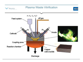
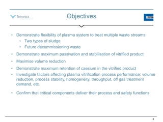
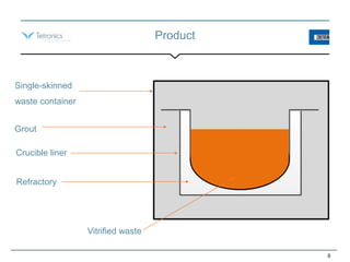
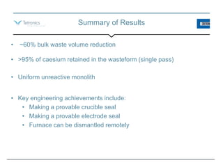
PLASMA WASTE VITRIFICATION
Dr Bryony Livesey*, Dr Tim Johnson+, Mark Rogers*
*Costain, +Tetronics International
International Workshop on Plasmas for Energy and Environmental Applications
Meeting national needs through people and innovation
Nuclear waste – long term storage
Plasma Waste Vitrification
Objectives
4
• Demonstrate flexibility of plasma system to treat multiple waste streams:
• Two types of sludge
• Future decommissioning waste
• Demonstrate maximum passivation and stabilisation of vitrified product
• Maximise volume reduction
• Demonstrate maximum retention of caesium in the vitrified product
• Investigate factors affecting plasma vitrification process performance: volume
reduction, process stability, homogeneity, throughput, off gas treatment
demand, etc.
• Confirm that critical components deliver their process and safety functions
Basis of Safety
• System is always a net-consumer of energy (i.e. no thermal runaway)
• Process prevents accumulation of explosive gases
• Standard nuclear ventilation and shielding suitable for dealing with
radiological hazard
• Criticality hazard managed by geometry
• Multi-layer containment of melt
• Avoidance of melt pouring – solidification in-situ
• Replaceable furnace refractory lining
• Melting crucible suitable for loading directly into final waste container for
ultimate disposal
5
Design of Demonstration Plant
• Based on concept design and corresponding safety case
• Key design features include:
• Remote loading of crucible into cooling jacket
• Remote vertical and horizontal movement of crucible
• Monitoring of furnace seal integrity
• Furnace clamp mechanisms
• Replaceable roof refractory
6
Demonstration Plant
• Feeding of sludges
and fluxes
• Twin electrodes
• Plant cell (cage)
• Plasma furnace
• Water-cooled ‘clam
shell’ and base
• Remote loading and
unloading of
crucible
• Simulated final
waste container
7
Product
8
Single-skinned
waste container
Vitrified waste
Grout
Crucible liner
Refractory
Slag Composition Control
9
• Fluxes are added to ensure low melting point
and good fluidity
• Allowing the material to solidify in-situ
reduces accuracy of composition control
required
Species SIXEP Magnox FD waste
Raw waste simulants 100 % 59% 92%
Silica sand, flux - 30% -
Aluminium oxide, flux - 11% -
Calcium Carbonate, flux - - 8%
Total 100 % 100 % 100 %
Mass Balance – SIXEP Sludge
10
Inputs: Mass, kg % of Input
Solid in waste simulant 553.51 63.0%
Water in waste simulant 325.08 37.0%
Flux in blended waste simulant 0.00 0.00%
Total mass input 878.59 100.0%
Outputs:
Vitrified slag 446 50.8%
Furnace exit duct dust 1.51 0.2%
Combustion chamber dust 0.12 0.0%
Filter bag-house dust 9.14 1.0%
Total solid mass output 456.77 52.0%
Volume Reduction
11
SIXEP Trial No SIXEP001 SIXEP002 SIXEP003 SIXEP004 SIXEP005
Feeding method Batch Continuous Continuous Continuous Continuous
Sludge fed during trial, m3 0.112 0.112 0.112 0.112 0.139
Vitrified slag volume, m3 0.076 0.043 0.043 0.043 0.065
Volume reduction (without crucible) 32% 61% 61% 61% 53%
Maximum vitrifed slag volume, m3 0.108 0.108 0.108 0.108 0.108
Sludge volume required, m3 0.158 0.280 0.280 0.280 0.231
Maximum final wasteform volume, m3 0.278 0.278 0.278 0.278 0.278
Volume reduction (with crucible) -76% 1% 1% 1% -20%
These values are following initial demonstration
trials designed with conservative assumptions and
limited optimisation studies. Further design
modifications for specific waste streams will result
in improved volume reduction performance.
Summary of Results
• ~60% bulk waste volume reduction
• >95% of caesium retained in the wasteform (single pass)
• Uniform unreactive monolith
• Key engineering achievements include:
• Making a provable crucible seal
• Making a provable electrode seal
• Furnace can be dismantled remotely
Next Steps
13
• Pursuing low hazard industrial implementation opportunities at full
scale
• Pursuing funding for active demonstration as the next step towards
commercial-scale implementation
• Developing the existing business case to explore the benefits of this
approach across the nuclear industry
Summary
14

Plasma Waste Vitrification

  • 1.
    PLASMA WASTE VITRIFICATION DrBryony Livesey*, Dr Tim Johnson+, Mark Rogers* *Costain, +Tetronics International International Workshop on Plasmas for Energy and Environmental Applications Meeting national needs through people and innovation
  • 2.
    Nuclear waste –long term storage
  • 3.
  • 4.
    Objectives 4 • Demonstrate flexibilityof plasma system to treat multiple waste streams: • Two types of sludge • Future decommissioning waste • Demonstrate maximum passivation and stabilisation of vitrified product • Maximise volume reduction • Demonstrate maximum retention of caesium in the vitrified product • Investigate factors affecting plasma vitrification process performance: volume reduction, process stability, homogeneity, throughput, off gas treatment demand, etc. • Confirm that critical components deliver their process and safety functions
  • 5.
    Basis of Safety •System is always a net-consumer of energy (i.e. no thermal runaway) • Process prevents accumulation of explosive gases • Standard nuclear ventilation and shielding suitable for dealing with radiological hazard • Criticality hazard managed by geometry • Multi-layer containment of melt • Avoidance of melt pouring – solidification in-situ • Replaceable furnace refractory lining • Melting crucible suitable for loading directly into final waste container for ultimate disposal 5
  • 6.
    Design of DemonstrationPlant • Based on concept design and corresponding safety case • Key design features include: • Remote loading of crucible into cooling jacket • Remote vertical and horizontal movement of crucible • Monitoring of furnace seal integrity • Furnace clamp mechanisms • Replaceable roof refractory 6
  • 7.
    Demonstration Plant • Feedingof sludges and fluxes • Twin electrodes • Plant cell (cage) • Plasma furnace • Water-cooled ‘clam shell’ and base • Remote loading and unloading of crucible • Simulated final waste container 7
  • 8.
  • 9.
    Slag Composition Control 9 •Fluxes are added to ensure low melting point and good fluidity • Allowing the material to solidify in-situ reduces accuracy of composition control required Species SIXEP Magnox FD waste Raw waste simulants 100 % 59% 92% Silica sand, flux - 30% - Aluminium oxide, flux - 11% - Calcium Carbonate, flux - - 8% Total 100 % 100 % 100 %
  • 10.
    Mass Balance –SIXEP Sludge 10 Inputs: Mass, kg % of Input Solid in waste simulant 553.51 63.0% Water in waste simulant 325.08 37.0% Flux in blended waste simulant 0.00 0.00% Total mass input 878.59 100.0% Outputs: Vitrified slag 446 50.8% Furnace exit duct dust 1.51 0.2% Combustion chamber dust 0.12 0.0% Filter bag-house dust 9.14 1.0% Total solid mass output 456.77 52.0%
  • 11.
    Volume Reduction 11 SIXEP TrialNo SIXEP001 SIXEP002 SIXEP003 SIXEP004 SIXEP005 Feeding method Batch Continuous Continuous Continuous Continuous Sludge fed during trial, m3 0.112 0.112 0.112 0.112 0.139 Vitrified slag volume, m3 0.076 0.043 0.043 0.043 0.065 Volume reduction (without crucible) 32% 61% 61% 61% 53% Maximum vitrifed slag volume, m3 0.108 0.108 0.108 0.108 0.108 Sludge volume required, m3 0.158 0.280 0.280 0.280 0.231 Maximum final wasteform volume, m3 0.278 0.278 0.278 0.278 0.278 Volume reduction (with crucible) -76% 1% 1% 1% -20% These values are following initial demonstration trials designed with conservative assumptions and limited optimisation studies. Further design modifications for specific waste streams will result in improved volume reduction performance.
  • 12.
    Summary of Results •~60% bulk waste volume reduction • >95% of caesium retained in the wasteform (single pass) • Uniform unreactive monolith • Key engineering achievements include: • Making a provable crucible seal • Making a provable electrode seal • Furnace can be dismantled remotely
  • 13.
    Next Steps 13 • Pursuinglow hazard industrial implementation opportunities at full scale • Pursuing funding for active demonstration as the next step towards commercial-scale implementation • Developing the existing business case to explore the benefits of this approach across the nuclear industry
  • 14.