This document describes the sulfur removal system for a natural gas plant. It contains the following key points:
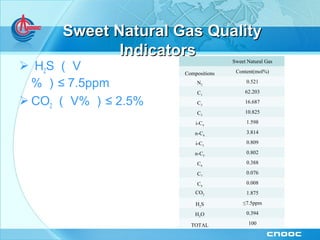
1. The system has a processing capacity of 71 mmscfd of sour natural gas and uses MDEA to selectively remove H2S and produce sweet natural gas containing less than 7.5 ppm of H2S.
2. The process flow involves absorption of acid gases like H2S in an amine absorber, flashing of the rich amine, amine regeneration, and preparation and recycling of the lean amine.
3. Safety systems include safety valves, interlock shutdown systems, gas detection alarms, purging lines, and fire hydrants to safely handle startup, shutdown and operation