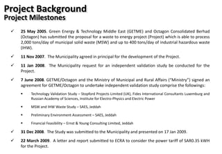
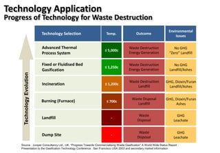
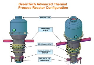
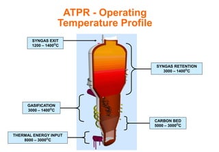
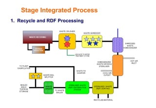
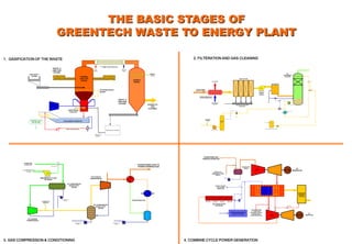
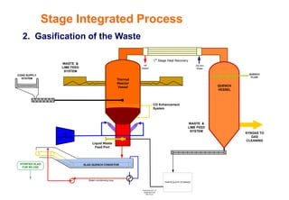
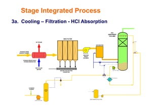
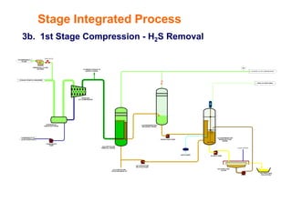
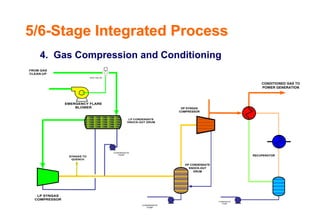
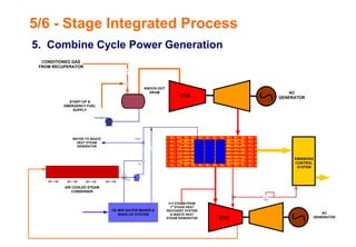
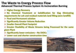
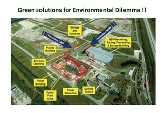
Proposed Development of a Waste to Energy Plant for
Jeddah Municipality, KSA
A PRESENTATION TO
Gulf Environment Forum (7-9 March 2010)
By
Prof. Dr Mamdouh F. Abdel-Sabour
Head of Environmental Studies Department
Saudi ASMA Environmental Solution (SAES)
S T R I C T L Y P R I V A T E & C O N F I D E N T I A L
In Collaboration
Ministry of Municipal and Rural Affairs
Municipality of Jeddah Province
Project Background
Project Milestones
 25 May 2005. Green Energy & Technology Middle East (GETME) and Octagon Consolidated Berhad
(Octagon) has submitted the proposal for a waste to energy project (Project) which is able to process
2,000 tons/day of municipal solid waste (MSW) and up to 400 tons/day of industrial hazardous waste
(IHW).
 11 Nov 2007. The Municipality agreed in principal for the development of the Project.
 11 Jan 2008. The Municipality request for an independent validation study be conducted for the
Project.
 7 June 2008. GETME/Octagon and the Ministry of Municipal and Rural Affairs (“Ministry”) signed an
agreement for GETME/Octagon to undertake independent validation study comprise the followings:
 Technology Validation Study – Stopford Projects Limited (UK), Fides International Consultants Luxemburg and
Russian Academy of Sciences, Institute for Electro-Physics and Electric Power
 MSW and IHW Waste Study – SAES, Jeddah
 Preliminary Environment Assessment – SAES, Jeddah
 Financial Feasibility – Ernst & Young Consulting Limited, Jeddah
 31 Dec 2008. The Study was submitted to the Municipality and presented on 17 Jan 2009.
 22 March 2009. A letter and report submitted to ECRA to consider the power tariff of SAR0.35 kWH
for the Project.
 Improve the environmental and health standards in the city of and
its suburbs through hygienic treatment of MSW.
 The project will convert untreated MSW and IHW into renewable
energy. This will reduce methane (a potent greenhouse gas)
generation from landfills, odour, health hazards and leachate
contamination of ground water that are currently being caused as a
result of disposal of MSW and IHW.
 The project is consistent with government objectives in promoting
an environmentally beneficial project that will significantly improve
waste management, promote renewable energy generation and
reduce the emissions of green house gases.
 Reduce requirement of landfill area for dumping of MSW and IHW,
thereby freeing up land resources for other socially beneficial usage.
 Expand the range of energy generation sources by promoting the
development of renewable energy projects to meet a part of the
energy requirements.
 Promote private sector participation and investment in clean and
renewable energy projects.
Project Benefits
Source : Juniper Consultancy Ltd., UK. “Progress Towards Commercialising Waste Gasification” A World Wide Status Report :
Presentation to the Gasification Technology Conference : San Francisco USA 2003 and secondary market information
≤ 5,000c
≤ 1,250c
≤ 1,200c
≤ 700c
-
Advanced Thermal
Process System
Fixed or Fluidised Bed
Gasification
Incineration
Burning (Furnace)
Landfill
Waste Destruction
Energy Generation
Waste Destruction
Energy Generation
Waste Destruction
Landfill
Waste Disposal
Landfill
Waste
Disposal
-Dump Site
Waste
Disposal
No GHG
“Zero” Landfill
No GHG
Landfill/Ashes
GHG, Dioxin/Furan
Landfill/Ashes
GHG, Dioxin/Furan
Ashes
GHG
Leachate
GHG
Leachate
Temp.Technology Selection Outcome
Environmental
Issues
TechnologyEvolution
Technology Application
Progress of Technology for Waste Destruction
Technology improvement naturally draws increased capital cost but … the
improvements minimize or mitigate adverse environmental and health
impacts
Dumping Landfill Sanitary
Landfill
Incinerator Gasification Advanced Thermal
Process System
Water source
contamination
Air pollution
impacts
Overall
environmental
costs
Various waste
disposal
technologies
Uncontrolled leachate: high risk
of water contamination
Moderate risk of water
contamination
Controlled leachate:
Minimised water contamination
Moderate to high risk of air
pollution from methane
Moderate risk of air
pollution from methane
Risk of air pollution from
furans & dioxins presents
No risk of
air pollution
Prospect for
energy
recovery
No prospect of recovery of
energy waste
Minimal prospect of recovery
of energy from waste
HIGH
High prospect of recovery of energy waste
(energy recovery is maximised)
MODERATE LOW NEGLIGLIBLE
Tipping Fees
per Ton
Technology Application
Progress of Technology for Waste Destruction
 Higher awareness of environmental, safety and health
impacts
 More stringent requirement for compliance with emission
standards
 Land scarcity
 Drawing the most efficient recovery of energy from wastes
 Not least, escalating fuel prices which makes fossil fuel
more expensive for power generation
 Competitive cost of technology over time
Waste disposal technology improves over time as a result of,
inter-alia :-
Technology Application
Progress of Technology for Waste Destruction
Plasma Torch
GreenTech Advanced Thermal
Process Reactor Configuration
SYNGAS EXIT
WASTE FEED
PORTS
CO ENHANCEMENT
THERMAL ENERGY
SYSTEM
MOLTEN SLAG
TAPPING PORT
ATPR - Operating
Temperature Profile
SYNGAS EXIT
1200 – 1400O
C
GASIFICATION
3000 – 1400O
C
SYNGAS RETENTION
3000 – 1400O
C
CARBON BED
5000 – 3000O
C
THERMAL ENERGY INPUT
8000 – 3000O
C
1. Recycle and RDF Processing
Stage Integrated Process
1. GASIFICATION OF THE WASTE 2. FILTERATION AND GAS CLEANING
3. GAS COMPRESSION & CONDITIONING 4. COMBINE CYCLE POWER GENERATION
THE BASIC STAGES OF
GREENTECH WASTE TO ENERGY PLANT
LP SYNGAS
COMPRESSOR
ESD VALVE
EMERGENCY FLARE
BLOWER
LP CONDENSATE
KNOCK-OUT
DRUM
CONDENSATE
PUMP
HP CONDENSATE
KNOCK-OUT
DRUM
HP SYNGAS
COMPRESSOR
CONDENSATE
PUMP
TO EMERGENCY
FLARE
SYNGAS TO
QUENCH
FROM GAS
CLEAN-UP
RECUPERATOR
CONDENSATE
PUMP
CONDITIONED GAS TO
POWER GENERATION
FC on pH
LC
SATURATOR
BAG FILTER
INDUCED
DRAFT
BLOWER
HCl
ABSORBER
COLUMN
QUENCH
SOLUTION
DRUM
QUENCH FEED PUMP
RE-CYCLE PUMP
RE-CYCLE HEAT-X
FCV
FCV
FCV
SOLIDS COLLECTION
CONVEYOR
NAOH MAKEUP SOLUTION
SYNGAS WASTE HEAT
STEAM GENERATOR
SYNGAS FROM
QUENCH VESSEL
HP STEAM
ATOMIZED
SYNGAS
RE-CYCLED
WATER
VITIRFIED SLAG
FOR RE-USE
THERMAL
REACTOR
VESSEL
SLAG QUENCH CONVEYOR
QUENCH
VESSEL
PARTICULATE STORAGE
PARTICULATE TO
GASIFIER FOR
RECYCLE
COKE SUPPLY
SYSTEM
WASTE &
LIME FEED
SYSTEM
SYNGAS TO
GAS
CLEANING
QUENCH
FLUID
CO Enhancement
System
WASTE &
LIME FEED
SYSTEM
Torch Air
Compressor
1st
Stage Heat Recovery
HP
Steam
De-min
Water
Steam condensing loop
Liquid Waste
Feed Port
DE-MIN WATER MAKER &
MAKE-UP SYSTEM
FC
FCV
AIR COOLED STEAM
CONDENSER
EMISSIONS
CONTROL
SYSTEM
PCV
START-UP &
EMERGENCY FUEL
SUPPLY
4
KNOCK-OUT
DRUM
HEAT RECOVERY
STEAM GENERATOR
STG
AC
GENERATOR
FCDV
CONDITIONED GAS
FROM RECUPERATOR
CTG
AC
GENERATOR
H P STEAM FROM
1st
STAGE HEAT
RECOVERY SYSTEM
& WASTE HEAT
STEAM GENERATOR
WATER TO WASTE
HEAT STEAM
GENERATOR
2. Gasification of the Waste
VITIRFIED SLAG
FOR RE-USE
Thermal
Reactor
Vessel
SLAG QUENCH CONVEYOR
QUENCH
VESSEL
PARTICULATE STORAGE
PARTICULATE TO
GASIFIER FOR
RECYCLE
COKE SUPPLY
SYSTEM
WASTE &
LIME FEED
SYSTEM
SYNGAS TO
GAS
CLEANING
QUENCH
FLUID
CO Enhancement
System
WASTE &
LIME FEED
SYSTEM
Air
Compressor
1st
Stage Heat Recovery
HP
Steam
De-min
Water
Steam condensing loop
Liquid Waste
Feed Port
Stage Integrated Process
FC on pH
LC
SATURATOR
BAG FILTER
INDUCED
DRAFT
BLOWER
HCl
ABSORBER
COLUMN
QUENCH
SOLUTION
DRUM
QUENCH FEED PUMP
RE-CYCLE PUMP
RE-CYCLE HEAT-X
FCV
FCV
FCV
SOLIDS COLLECTION
CONVEYOR
NAOH MAKEUP SOLUTION
SYNGAS WASTE HEAT
STEAM GENERATOR
SYNGAS FROM
QUENCH VESSEL
HP STEAM
ATOMIZED
SYNGAS
RE-CYCLED
WATER
3a. Cooling – Filtration - HCl Absorption
Stage Integrated Process
SYNGAS FROM HCl ABSORBER
CONDENSATE TO
SLAG CONVEYOR
SOUR GAS
(LP) COMPRESSOR
TO EMERGENCY
FLARE
ESD VALVE
EMERGENCY FLARE
BLOWER
CONDENSATE
KNOCK-OUT DRUM
FLUSH WATER
SLURRY PUMP
AIR BLOWER
VENT TO SAFE AREA
SYNGAS TO HP COMPRESSOR
H2S CONTACTOR
REMOVAL VESSEL
H2S REGENERATION
DEGASSER VESSEL
H2
S REGENERATION
SURGE SETTLER
VESSEL
SULPHER CAKE
FILTER
SULPHER CAKE
COLLECTION
REGEN FEED PUMP
H2S CONTACTOR
RE-CYCLE PUMP
H2S CONTACTOR
SOLUTION MAKE-UP
28
CONDENSATE
PUMP
M
ATOMIZED SYNGAS TO
QUENCH VESSEL
3b. 1st Stage Compression - H2S Removal
Stage Integrated Process
HP CONDENSATE
KNOCK-OUT
DRUM
HP SYNGAS
COMPRESSOR
RECUPERATOR
CONDENSATE
PUMP
CONDITIONED GAS TO
POWER GENERATION
LP SYNGAS
COMPRESSOR
ESD VALVE
EMERGENCY FLARE
BLOWER
LP CONDENSATE
KNOCK-OUT DRUM
CONDENSATE
PUMP
CONDENSATE
PUMP
SYNGAS TO
QUENCH
FROM GAS
CLEAN-UP
5/6-Stage Integrated Process
4. Gas Compression and Conditioning
5. Combine Cycle Power Generation
5/6 - Stage Integrated Process
DE-MIN WATER MAKER &
MAKE-UP SYSTEM
FC
FCV
AIR COOLED STEAM
CONDENSER
EMISSIONS
CONTROL
SYSTEM
PCV
START-UP &
EMERGENCY FUEL
SUPPLY
4
KNOCK-OUT
DRUM
HEAT RECOVERY
STEAM GENERATOR
STG
AC
GENERATOR
FCDV
CONDITIONED GAS
FROM RECUPERATOR
CTG
AC
GENERATOR
H P STEAM FROM
1st
STAGE HEAT
RECOVERY SYSTEM
& WASTE HEAT
STEAM GENERATOR
WATER TO WASTE
HEAT STEAM
GENERATOR
DCS & System Monitoring
Z Z Z Z Z
V A Hz
HV/LV Switch Room
VSA Oxygen
Generation
Plant start-up
& Emergency
Power System PSA Nitrogen
Generation
Water Treatment
& Storage
Diesel Day Tank
Water
Storage
Firewater
Storage
Fire & Gas Detection
& Safety Systems
Water Cooling & Re-cycling
Safety Support and
Utility System
 Higher Energy Recovery
 No Chemical Treatment or Solidification for Slag Eliminating
requirements for ash and residual materials land filling (zero landfill)
 Final and Permanent solution
 Significantly Greater Volume Reduction
 Smaller Overall Plant Footprint
 Greater Flexibility of Waste Streams being Processed for the same
given Plant
 Significantly lower emissions – No SVOCs
 Lower cost and shorter construction time
The Waste to Energy Process Flow
Advanced Thermal Process System Vs Incineration Burning
Green solutions for Environmental Dilemma !!
Toyohashi, Japan Mitsui R1 2002 120,000 TPY
Kawaguchi, Japan Ebara 2002 125,000 TPY
Kazusa, Japan Nippon Steel 2002 60,000 TPY
Aomori, Japan Ebara 2001 135,000 TPY
Technology Track Record
Independent Validation and Experience
WTE Plants produce electricity “with less
environmental impact than almost any other source
of electricity” – US EPA
22
Technology Track Record
Independent Validation and Experience
 Russian Academy of Sciences, Institute for Electro-Physics and Electric Power.
“Calculations and experiments prove that plasma methods of waste and coal
treatment are economically beneficial and ecologically friendly. Plasma generators
operating on water vapour are the most promising for treatment of organic-containing
waste for syngas production”.
 Concept Engineering Design validated by Simon Carves Limited, UK.
 Front End Engineering Design undertaken by Stopford Projects Limited, UK (completed)
 Detailed engineering design undertaken by Stopford Projects Limited, UK (work in progress)
 Gasification Vessel Design and CO Enhancement validated by Stopford Projects Limited and
PSE, UK.
 Individual process is proven technologies undertaken by companies with strong track
record including: Fairport, UK (Waste Receiving, Sorting and RDF Production), Europlasma,
FR (Plasma Torches and Reactor Design), La Gas Integral, FR (Gas Processing), Peter
Brotherhood, UK (Gas Compression), General Electric, USA (MV Power Generation),
Caterpillar, USA (LV Power Generation), EPCC contractors in KSA (Civil and Utilities)
Technology Suitability
 Multiple feedstock capability
 Capable of receiving, handling, processing and disposing, different types of wastes (e.g., MSW, IHW) concurrently.
 Complete destruction of wastes
 Plasma gasification process is a NO BURN process hence, it does produce residuals, i.e., fly & bottom ashes as
typically found with incinerators.
 Fly & bottom ashes are harmful, may contain heavy metals and require secure landfilling. Since plasma gasification
does not produced ash, landfilling will no longer be a requirement.
 Maximum energy recovery from wastes
 Plasma gasification process is designed and engineered to ensure efficient energy recovery from wastes.
 Environmentally friendly
 Operating at temperature range of about 3,000oC in the Gasification Zone in an oxygen starved environment, are
realised in the plasma reactor therefore, plasma gasification process presents no opportunity for formation of
hazardous flue gases, e.g., dioxin & furans, SOx and Nox.
 Clean Development Mechanism under Kyoto Protocol
 Capable for qualification as CDM project, i.e., reduction of emission of methane typically from landfills and reduction
of CO2 emission from avoidance of use of fossil fuels for power generation.
Project Feasibility
Technology Suitability
 25 May 2005. Project Proposal
 11 Nov 2007. Agreement in Principal by the Municipality
 11 Jan 2008. Request for GETME/Octagon to undertake Independent Validation Study
(Study)
 7 June 2008. Agreement between GETME/Octagon and the Ministry of Municipal and
Rural Affairs (“Ministry”) for the Study
 31 Dec 2008. The Study submitted to Municipality and presented on 17 Jan 2009.
 22 March 2009. Report submitted to ECRA to consider power tariff of SAR0.35 kWH
 19 April 2009. Request Approval-in-Principal for Feed in Power Tariff subject to further
approvals from the relevant authorities
 May – Dec 2009. Municipality Award Process and Engineering Work
 Jan 2010. Execute Concession Agreement for MSW/IHW and Power Purchase Agreement
 March 2010. Commence Project Construction
 March 2012. Construction Completed
 June 2012. Plant Commissioning
Moving Forward
Request to ECRA
Thank You

WtE-Gulf forum presentation

  • 1.
    Proposed Development ofa Waste to Energy Plant for Jeddah Municipality, KSA A PRESENTATION TO Gulf Environment Forum (7-9 March 2010) By Prof. Dr Mamdouh F. Abdel-Sabour Head of Environmental Studies Department Saudi ASMA Environmental Solution (SAES) S T R I C T L Y P R I V A T E & C O N F I D E N T I A L In Collaboration Ministry of Municipal and Rural Affairs Municipality of Jeddah Province
  • 2.
    Project Background Project Milestones 25 May 2005. Green Energy & Technology Middle East (GETME) and Octagon Consolidated Berhad (Octagon) has submitted the proposal for a waste to energy project (Project) which is able to process 2,000 tons/day of municipal solid waste (MSW) and up to 400 tons/day of industrial hazardous waste (IHW).  11 Nov 2007. The Municipality agreed in principal for the development of the Project.  11 Jan 2008. The Municipality request for an independent validation study be conducted for the Project.  7 June 2008. GETME/Octagon and the Ministry of Municipal and Rural Affairs (“Ministry”) signed an agreement for GETME/Octagon to undertake independent validation study comprise the followings:  Technology Validation Study – Stopford Projects Limited (UK), Fides International Consultants Luxemburg and Russian Academy of Sciences, Institute for Electro-Physics and Electric Power  MSW and IHW Waste Study – SAES, Jeddah  Preliminary Environment Assessment – SAES, Jeddah  Financial Feasibility – Ernst & Young Consulting Limited, Jeddah  31 Dec 2008. The Study was submitted to the Municipality and presented on 17 Jan 2009.  22 March 2009. A letter and report submitted to ECRA to consider the power tariff of SAR0.35 kWH for the Project.
  • 3.
     Improve theenvironmental and health standards in the city of and its suburbs through hygienic treatment of MSW.  The project will convert untreated MSW and IHW into renewable energy. This will reduce methane (a potent greenhouse gas) generation from landfills, odour, health hazards and leachate contamination of ground water that are currently being caused as a result of disposal of MSW and IHW.  The project is consistent with government objectives in promoting an environmentally beneficial project that will significantly improve waste management, promote renewable energy generation and reduce the emissions of green house gases.  Reduce requirement of landfill area for dumping of MSW and IHW, thereby freeing up land resources for other socially beneficial usage.  Expand the range of energy generation sources by promoting the development of renewable energy projects to meet a part of the energy requirements.  Promote private sector participation and investment in clean and renewable energy projects. Project Benefits
  • 4.
    Source : JuniperConsultancy Ltd., UK. “Progress Towards Commercialising Waste Gasification” A World Wide Status Report : Presentation to the Gasification Technology Conference : San Francisco USA 2003 and secondary market information ≤ 5,000c ≤ 1,250c ≤ 1,200c ≤ 700c - Advanced Thermal Process System Fixed or Fluidised Bed Gasification Incineration Burning (Furnace) Landfill Waste Destruction Energy Generation Waste Destruction Energy Generation Waste Destruction Landfill Waste Disposal Landfill Waste Disposal -Dump Site Waste Disposal No GHG “Zero” Landfill No GHG Landfill/Ashes GHG, Dioxin/Furan Landfill/Ashes GHG, Dioxin/Furan Ashes GHG Leachate GHG Leachate Temp.Technology Selection Outcome Environmental Issues TechnologyEvolution Technology Application Progress of Technology for Waste Destruction
  • 5.
    Technology improvement naturallydraws increased capital cost but … the improvements minimize or mitigate adverse environmental and health impacts Dumping Landfill Sanitary Landfill Incinerator Gasification Advanced Thermal Process System Water source contamination Air pollution impacts Overall environmental costs Various waste disposal technologies Uncontrolled leachate: high risk of water contamination Moderate risk of water contamination Controlled leachate: Minimised water contamination Moderate to high risk of air pollution from methane Moderate risk of air pollution from methane Risk of air pollution from furans & dioxins presents No risk of air pollution Prospect for energy recovery No prospect of recovery of energy waste Minimal prospect of recovery of energy from waste HIGH High prospect of recovery of energy waste (energy recovery is maximised) MODERATE LOW NEGLIGLIBLE Tipping Fees per Ton Technology Application Progress of Technology for Waste Destruction
  • 6.
     Higher awarenessof environmental, safety and health impacts  More stringent requirement for compliance with emission standards  Land scarcity  Drawing the most efficient recovery of energy from wastes  Not least, escalating fuel prices which makes fossil fuel more expensive for power generation  Competitive cost of technology over time Waste disposal technology improves over time as a result of, inter-alia :- Technology Application Progress of Technology for Waste Destruction
  • 7.
  • 9.
    GreenTech Advanced Thermal ProcessReactor Configuration SYNGAS EXIT WASTE FEED PORTS CO ENHANCEMENT THERMAL ENERGY SYSTEM MOLTEN SLAG TAPPING PORT
  • 10.
    ATPR - Operating TemperatureProfile SYNGAS EXIT 1200 – 1400O C GASIFICATION 3000 – 1400O C SYNGAS RETENTION 3000 – 1400O C CARBON BED 5000 – 3000O C THERMAL ENERGY INPUT 8000 – 3000O C
  • 11.
    1. Recycle andRDF Processing Stage Integrated Process
  • 12.
    1. GASIFICATION OFTHE WASTE 2. FILTERATION AND GAS CLEANING 3. GAS COMPRESSION & CONDITIONING 4. COMBINE CYCLE POWER GENERATION THE BASIC STAGES OF GREENTECH WASTE TO ENERGY PLANT LP SYNGAS COMPRESSOR ESD VALVE EMERGENCY FLARE BLOWER LP CONDENSATE KNOCK-OUT DRUM CONDENSATE PUMP HP CONDENSATE KNOCK-OUT DRUM HP SYNGAS COMPRESSOR CONDENSATE PUMP TO EMERGENCY FLARE SYNGAS TO QUENCH FROM GAS CLEAN-UP RECUPERATOR CONDENSATE PUMP CONDITIONED GAS TO POWER GENERATION FC on pH LC SATURATOR BAG FILTER INDUCED DRAFT BLOWER HCl ABSORBER COLUMN QUENCH SOLUTION DRUM QUENCH FEED PUMP RE-CYCLE PUMP RE-CYCLE HEAT-X FCV FCV FCV SOLIDS COLLECTION CONVEYOR NAOH MAKEUP SOLUTION SYNGAS WASTE HEAT STEAM GENERATOR SYNGAS FROM QUENCH VESSEL HP STEAM ATOMIZED SYNGAS RE-CYCLED WATER VITIRFIED SLAG FOR RE-USE THERMAL REACTOR VESSEL SLAG QUENCH CONVEYOR QUENCH VESSEL PARTICULATE STORAGE PARTICULATE TO GASIFIER FOR RECYCLE COKE SUPPLY SYSTEM WASTE & LIME FEED SYSTEM SYNGAS TO GAS CLEANING QUENCH FLUID CO Enhancement System WASTE & LIME FEED SYSTEM Torch Air Compressor 1st Stage Heat Recovery HP Steam De-min Water Steam condensing loop Liquid Waste Feed Port DE-MIN WATER MAKER & MAKE-UP SYSTEM FC FCV AIR COOLED STEAM CONDENSER EMISSIONS CONTROL SYSTEM PCV START-UP & EMERGENCY FUEL SUPPLY 4 KNOCK-OUT DRUM HEAT RECOVERY STEAM GENERATOR STG AC GENERATOR FCDV CONDITIONED GAS FROM RECUPERATOR CTG AC GENERATOR H P STEAM FROM 1st STAGE HEAT RECOVERY SYSTEM & WASTE HEAT STEAM GENERATOR WATER TO WASTE HEAT STEAM GENERATOR
  • 13.
    2. Gasification ofthe Waste VITIRFIED SLAG FOR RE-USE Thermal Reactor Vessel SLAG QUENCH CONVEYOR QUENCH VESSEL PARTICULATE STORAGE PARTICULATE TO GASIFIER FOR RECYCLE COKE SUPPLY SYSTEM WASTE & LIME FEED SYSTEM SYNGAS TO GAS CLEANING QUENCH FLUID CO Enhancement System WASTE & LIME FEED SYSTEM Air Compressor 1st Stage Heat Recovery HP Steam De-min Water Steam condensing loop Liquid Waste Feed Port Stage Integrated Process
  • 14.
    FC on pH LC SATURATOR BAGFILTER INDUCED DRAFT BLOWER HCl ABSORBER COLUMN QUENCH SOLUTION DRUM QUENCH FEED PUMP RE-CYCLE PUMP RE-CYCLE HEAT-X FCV FCV FCV SOLIDS COLLECTION CONVEYOR NAOH MAKEUP SOLUTION SYNGAS WASTE HEAT STEAM GENERATOR SYNGAS FROM QUENCH VESSEL HP STEAM ATOMIZED SYNGAS RE-CYCLED WATER 3a. Cooling – Filtration - HCl Absorption Stage Integrated Process
  • 15.
    SYNGAS FROM HClABSORBER CONDENSATE TO SLAG CONVEYOR SOUR GAS (LP) COMPRESSOR TO EMERGENCY FLARE ESD VALVE EMERGENCY FLARE BLOWER CONDENSATE KNOCK-OUT DRUM FLUSH WATER SLURRY PUMP AIR BLOWER VENT TO SAFE AREA SYNGAS TO HP COMPRESSOR H2S CONTACTOR REMOVAL VESSEL H2S REGENERATION DEGASSER VESSEL H2 S REGENERATION SURGE SETTLER VESSEL SULPHER CAKE FILTER SULPHER CAKE COLLECTION REGEN FEED PUMP H2S CONTACTOR RE-CYCLE PUMP H2S CONTACTOR SOLUTION MAKE-UP 28 CONDENSATE PUMP M ATOMIZED SYNGAS TO QUENCH VESSEL 3b. 1st Stage Compression - H2S Removal Stage Integrated Process
  • 16.
    HP CONDENSATE KNOCK-OUT DRUM HP SYNGAS COMPRESSOR RECUPERATOR CONDENSATE PUMP CONDITIONEDGAS TO POWER GENERATION LP SYNGAS COMPRESSOR ESD VALVE EMERGENCY FLARE BLOWER LP CONDENSATE KNOCK-OUT DRUM CONDENSATE PUMP CONDENSATE PUMP SYNGAS TO QUENCH FROM GAS CLEAN-UP 5/6-Stage Integrated Process 4. Gas Compression and Conditioning
  • 17.
    5. Combine CyclePower Generation 5/6 - Stage Integrated Process DE-MIN WATER MAKER & MAKE-UP SYSTEM FC FCV AIR COOLED STEAM CONDENSER EMISSIONS CONTROL SYSTEM PCV START-UP & EMERGENCY FUEL SUPPLY 4 KNOCK-OUT DRUM HEAT RECOVERY STEAM GENERATOR STG AC GENERATOR FCDV CONDITIONED GAS FROM RECUPERATOR CTG AC GENERATOR H P STEAM FROM 1st STAGE HEAT RECOVERY SYSTEM & WASTE HEAT STEAM GENERATOR WATER TO WASTE HEAT STEAM GENERATOR
  • 18.
    DCS & SystemMonitoring Z Z Z Z Z V A Hz HV/LV Switch Room VSA Oxygen Generation Plant start-up & Emergency Power System PSA Nitrogen Generation Water Treatment & Storage Diesel Day Tank Water Storage Firewater Storage Fire & Gas Detection & Safety Systems Water Cooling & Re-cycling Safety Support and Utility System
  • 19.
     Higher EnergyRecovery  No Chemical Treatment or Solidification for Slag Eliminating requirements for ash and residual materials land filling (zero landfill)  Final and Permanent solution  Significantly Greater Volume Reduction  Smaller Overall Plant Footprint  Greater Flexibility of Waste Streams being Processed for the same given Plant  Significantly lower emissions – No SVOCs  Lower cost and shorter construction time The Waste to Energy Process Flow Advanced Thermal Process System Vs Incineration Burning
  • 20.
    Green solutions forEnvironmental Dilemma !!
  • 21.
    Toyohashi, Japan MitsuiR1 2002 120,000 TPY Kawaguchi, Japan Ebara 2002 125,000 TPY Kazusa, Japan Nippon Steel 2002 60,000 TPY Aomori, Japan Ebara 2001 135,000 TPY Technology Track Record Independent Validation and Experience
  • 22.
    WTE Plants produceelectricity “with less environmental impact than almost any other source of electricity” – US EPA 22
  • 23.
    Technology Track Record IndependentValidation and Experience  Russian Academy of Sciences, Institute for Electro-Physics and Electric Power. “Calculations and experiments prove that plasma methods of waste and coal treatment are economically beneficial and ecologically friendly. Plasma generators operating on water vapour are the most promising for treatment of organic-containing waste for syngas production”.  Concept Engineering Design validated by Simon Carves Limited, UK.  Front End Engineering Design undertaken by Stopford Projects Limited, UK (completed)  Detailed engineering design undertaken by Stopford Projects Limited, UK (work in progress)  Gasification Vessel Design and CO Enhancement validated by Stopford Projects Limited and PSE, UK.  Individual process is proven technologies undertaken by companies with strong track record including: Fairport, UK (Waste Receiving, Sorting and RDF Production), Europlasma, FR (Plasma Torches and Reactor Design), La Gas Integral, FR (Gas Processing), Peter Brotherhood, UK (Gas Compression), General Electric, USA (MV Power Generation), Caterpillar, USA (LV Power Generation), EPCC contractors in KSA (Civil and Utilities)
  • 24.
    Technology Suitability  Multiplefeedstock capability  Capable of receiving, handling, processing and disposing, different types of wastes (e.g., MSW, IHW) concurrently.  Complete destruction of wastes  Plasma gasification process is a NO BURN process hence, it does produce residuals, i.e., fly & bottom ashes as typically found with incinerators.  Fly & bottom ashes are harmful, may contain heavy metals and require secure landfilling. Since plasma gasification does not produced ash, landfilling will no longer be a requirement.  Maximum energy recovery from wastes  Plasma gasification process is designed and engineered to ensure efficient energy recovery from wastes.  Environmentally friendly  Operating at temperature range of about 3,000oC in the Gasification Zone in an oxygen starved environment, are realised in the plasma reactor therefore, plasma gasification process presents no opportunity for formation of hazardous flue gases, e.g., dioxin & furans, SOx and Nox.  Clean Development Mechanism under Kyoto Protocol  Capable for qualification as CDM project, i.e., reduction of emission of methane typically from landfills and reduction of CO2 emission from avoidance of use of fossil fuels for power generation. Project Feasibility Technology Suitability
  • 25.
     25 May2005. Project Proposal  11 Nov 2007. Agreement in Principal by the Municipality  11 Jan 2008. Request for GETME/Octagon to undertake Independent Validation Study (Study)  7 June 2008. Agreement between GETME/Octagon and the Ministry of Municipal and Rural Affairs (“Ministry”) for the Study  31 Dec 2008. The Study submitted to Municipality and presented on 17 Jan 2009.  22 March 2009. Report submitted to ECRA to consider power tariff of SAR0.35 kWH  19 April 2009. Request Approval-in-Principal for Feed in Power Tariff subject to further approvals from the relevant authorities  May – Dec 2009. Municipality Award Process and Engineering Work  Jan 2010. Execute Concession Agreement for MSW/IHW and Power Purchase Agreement  March 2010. Commence Project Construction  March 2012. Construction Completed  June 2012. Plant Commissioning Moving Forward Request to ECRA
  • 26.