Definition
Piping:
…assemblies ofpiping components used…[for] fluid flows. Piping also
includes pipe supporting elements, but does not include support structures…
or equipment…
Piping system:
…interconnected piping subject to the same design conditions
Piping components:
…mechanical elements suitable for joining or assembly into pressure tight
fluid-containing piping systems…pipes, fittings, flanges, gaskets, bolting,
valves and special devices such as expansion joints.
5.
Codes & Standardsfor Piping
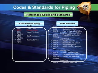
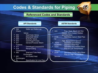
Referenced Codes and Standards
ASME Standards
B16.5 Pipe Flanges & Flange Fitting
B16.9 Buttwelding Fitting
B16.10 Face to Face & End to End
Dimension of Ferrous Valves
B16.11 Forged Fittings, Socket
Welding
and Threaded
B16.20 Metallic Gaskets
B16.21 Nonmetallic Flat Gasket
B16.25 Butt Welding Ends
B16.34 Valve – Flange, Threaded
and
Welding End
B16.36 Steel Orifice Flanges
B16.47 Large Diameter Steel Flange
B36.10M Welded and Seamless
Wrought
Steel Pipe
B36.19 Stainless Steel Pipe
B31.1 Power Piping
B31.3 Process Piping
B31.4 Liquid Petroleum
Pipeline
B31.8 Gas Transmission
Pipeline
B31.9 Building Services
Piping
ASME Pressure Piping
Code
6.
Codes & Standardsfor Piping
ASTM Standards
A53 Pipe, Steel, Black and Hot-
Dipped, Zinc-Coated Welded
and Seamless
A106 Seamless Carbon Steel Pipe
for
High Temperature Service
A312 Seamless and Welded
Austenitic Stainless Steel Pipe
A333 Seamless and Welded Steel
Pipe for Low Temperature
Service
A335 Seamless Ferritic Alloy-Steel
Pipe for High Temperature
Service
594 Wafer and Wafer-Lug
Check
Valves
600 Steel Gate Valves
608 Metal Ball Valves
609 Butterfly Valves
610 Centrifugal Pumps
611 General Purpose Steam
Turbines
617 Centrifugal Compressors
618 Reciprocating
Compressors
660 Shell and Tube Heat
Exchangers
661 Air Cooled Heat
Exchangers
5L Specification for Line Pipe
API Standards
Referenced Codes and Standards
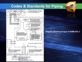
Codes & Standardsfor Piping
Scope of ASME B31.3
Rules for the Process Piping Code Section B31.3 have been developed considering piping
typically found in petroleum refineries; chemical, pharmaceutical, textile, paper, semiconductor,
and cryogenic plants; and related processing plants and terminals. [300.1]
This Code applies for all fluids including:
Row, intermediate and finished chemicals
Petroleum products
Gas, steam, air and water
Fluidized solids
Refrigerants
Cryogenic fluids
This Code excludes the following:
Piping systems designed for internal gage pressures at or above zero but less than 105
kPa (15 psi)
Fluid handled is nonflammable, nontoxic, and not damaging to human tissues
Power boilers in accordance with BPV Code Section I and boiler external piping which is
required to conform to B31.1
Tube headers and manifolds of fired heaters
Pressure vessels, heat exchangers, pumps, compressors and processing equipment,
including internal piping and connections for external piping
9.
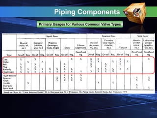
Piping Components
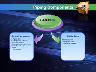
General Components
2Components
Special Items
Pipe & Tube
Fittings (e.g. elbows,
reducers, branch,
connections, flanges, etc.)
Gaskets, bolt & nut
Valves
Pipe support
Spring support
Expansion joint
Low friction device
10.
Piping Components
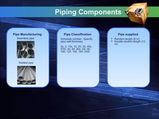
Pipe Manufacturing
Seamlesspipe
Welded pipe
Pipe Classification Pipe supplied
Schedule number : Specify
pipe wall thickness
5s, 5, 10s, 10, 20, 30, 40s,
STD, 40, 60, 80s, XS, 80,
100, 120, 140, 160, XXS
Random length (6 m)
Double random length (12
m)
11.
Piping Components
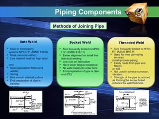
Butt Weld
Used in most piping
systems NPS ≥ 2” (ASME B16.9)
Most common method
Low material cost but high labor
cost
Need specialized fitters and
welder
Strong
Has smooth internal surface
End preparation of pipe is
beveled
end (BE)
Used generally not restricted
Threaded Weld
Size frequently limited to NPS≤
1½” (ASME B16.11)
Used for lines conveying
services
(small process piping)
Easily made from pipe and
fittings
on site
Not used in service corrosion,
vibration
Strength of the pipe is reduced,
as forming the screw thread
reduces the wall thickness
Socket Weld
Size frequently limited to NPS≤
1 ½” (ASME B16.11)
Easier alignment on small line
than butt welding
Low cost on fabrication
Have lower fatigue resistance
No weld metal can enter bore
End preparation of pipe is plain
end (PE)
Methods of Joining Pipe
12.
Piping Components
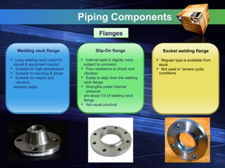
Welding neckflange
Long welding neck (used for
vessel & equipment nozzle)
Suitable for high temperature
Suitable for bending & Shear
Suitable for impact and
vibration
stresses apply
Socket welding flange
Regular type is available from
stock
Not used in “severe cyclic
conditions
Slip-On flange
Internal weld is slightly more
subject to corrosion
Poor resistance to chock and
vibration
Easily to align than the welding
neck flange
Strengths under internal
pressure
are about 1/3 of welding neck
flange
Not usual practical
Flanges
13.
Piping Components
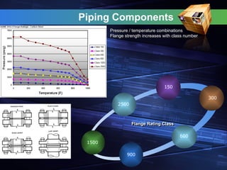
Pressure /temperature combinations
Flange strength increases with class number
150
300
600
900
Flange Rating Class
1500
2500
14.
Piping Components
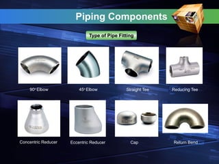
Type ofPipe Fitting
90o
Elbow 45o
Elbow Straight Tee Reducing Tee
Concentric Reducer Eccentric Reducer Cap Return Bend
Piping Components
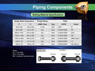
Bolting MaterialSpecifications
Design Metal Temperature Flange Rating Bolts
o
F o
C ASME Class Type ASTM Grade
-20 to 400 -29 to 204 ≤ 150 Bolt A307 B
-20 to 800 -29 to 427 Any Stud A193/A193M B7
800 to 1100 427 to 593 Any Stud A193/A193M B16
1100 to 1200 593 to 650 Any Stud A193/A193M B5
1100 to 1500 593 to 815 ≤ 300 Stud A193/A193M B8M Class 1
-150 to -20 -101 to -29 Any Stud A320/A320M L7
-325 to -20 -198 to -29 Any Stud A320/A320M B8 Class 2
Notes :
B7 = Low alloy
B16 = Low alloy
B8 = Austenitic stainless steel
18.
Piping Components
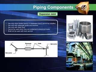
Useonly when limited space or expansion bend cannot be installed
Use only with adequate guide and anchors
Use only with clean fluid
Cannot be used when they are subjected to tensional loads
Shall not be used with toxic service
Expansion Joint
19.
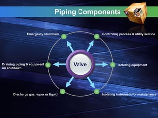
Controlling process &utility service
Emergency shutdown
Isolating equipment
Isolating instrument for maintenance
Draining piping & equipment
on shutdown
Discharge gas, vapor or liquid
Valve
Piping Components
20.
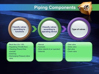
Piping Components
Classify valves
accordingto
functions
Classify valves
according to
operating device
Type of valves
- Block flow (On / Off)
- Regulating (Throttle flow)
- Checking (Prevent flow
reversal)
- Switching
- Discharging (Pressure relive
valve
- Manual
- Hydraulic
- Motor (electric & air operated)
- Solenoid
- Gate valve
- Globe valve
- Ball valve
- Check valve
21.
Piping Components
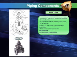
- Anoptimum engineering and economic choice
for on/off service
- Suitable for most fluids including steam, water,
oil, air and gas
- About 75% of all valves in process plants
Advantage:
- Small pressure drop across valve
Disadvantage:
- Poor throttling characteristics
Gate Valve
22.
Piping Components
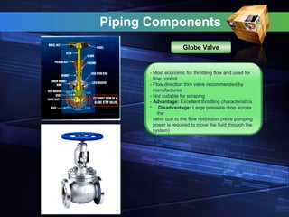
- Mosteconomic for throttling flow and used for
flow control
- Flow direction thru valve recommended by
manufactures
- Not suitable for scraping
- Advantage: Excellent throttling characteristics
- Disadvantage: Large pressure drop across
the
valve due to the flow restriction (more pumping
power is required to move the fluid through the
system)
Globe Valve
23.
Piping Components
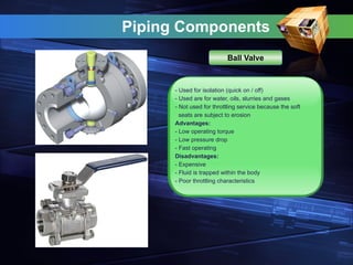
- Usedfor isolation (quick on / off)
- Used are for water, oils, slurries and gases
- Not used for throttling service because the soft
seats are subject to erosion
Advantages:
- Low operating torque
- Low pressure drop
- Fast operating
Disadvantages:
- Expensive
- Fluid is trapped within the body
- Poor throttling characteristics
Ball Valve
24.
Piping Components
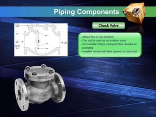
- Allowsflow in one direction
- Can not be used as an isolation valve
- Not suitable if there is frequent flow reversal as
pounding
- Installed vertical with flow upward, or horizontal
Check Valve
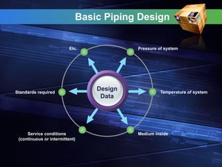
Pressure of system
Etc.
Temperatureof system
Medium inside
Standards required
Service conditions
(continuous or intermittent)
Design
Data
Basic Piping Design
27.
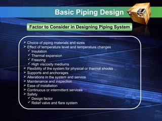
Basic Piping Design
Factorto Consider in Designing Piping System
Choice of piping materials and sizes
Effect of temperature level and temperature changes
Insulation
Thermal expansion
Freezing
High viscosity mediums
Flexibility of the system for physical or thermal shocks
Supports and anchorages
Alterations in the system and service
Maintenance and inspection
Ease of installation
Continuous or intermittent services
Safety
Design factor
Relief valve and flare system
28.
Basic Piping Design
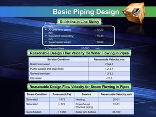
Guidelinein Line Sizing
Water and other liquids : 0.5-5
m/s
Air and other gases : 10-20
m/s
Saturated steam (Dry) : 15-30
m/s
Superheated steam : 30-60
m/s
Vacuum lines : 10-100 m/s
Reasonable Design Flow Velocity for Water Flowing in Pipes
Service Condition Reasonable Velocity, m/s
Boiler feed water 2.5-4.6
Pump suction and drain lines 1.2-2.1
General services 1.2-3.0
City water < 2.1
Reasonable Design Flow Velocity for Steam Flowing in Pipes
Steam Condition Pressure (kPa) Service Reasonable Velocity, m/s
Saturated 1-175 Heating 20-31
Saturated > 175 Powerhouse
Process piping
31-51
Superheated > 1380 Boiler and turbine 36-100
29.
Basic Piping Design
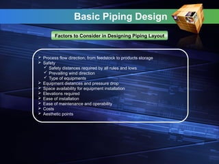
Factorsto Consider in Designing Piping Layout
Process flow direction; from feedstock to products storage
Safety
Safety distances required by all rules and lows
Prevailing wind direction
Type of equipments
Equipment distances and pressure drop
Space availability for equipment installation
Elevations required
Ease of installation
Ease of maintenance and operability
Costs
Aesthetic points
Basic Piping Design
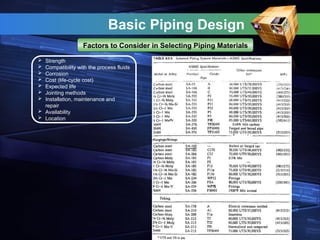
Factorsto Consider in Selecting Piping Materials
Strength
Compatibility with the process fluids
Corrosion
Cost (life-cycle cost)
Expected life
Jointing methods
Installation, maintenance and
repair
Availability
Location
34.
Basic Piping Design
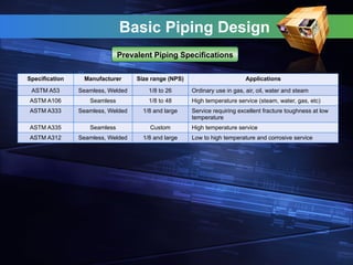
SpecificationManufacturer Size range (NPS) Applications
ASTM A53 Seamless, Welded 1/8 to 26 Ordinary use in gas, air, oil, water and steam
ASTM A106 Seamless 1/8 to 48 High temperature service (steam, water, gas, etc)
ASTM A333 Seamless, Welded 1/8 and large Service requiring excellent fracture toughness at low
temperature
ASTM A335 Seamless Custom High temperature service
ASTM A312 Seamless, Welded 1/8 and large Low to high temperature and corrosive service
Prevalent Piping Specifications
35.
Basic Piping Design
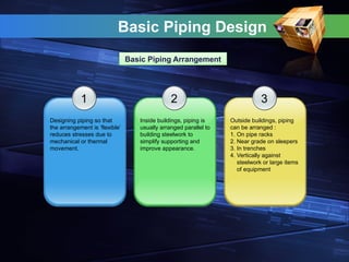
1
Designingpiping so that
the arrangement is ‘flexible’
reduces stresses due to
mechanical or thermal
movement.
2
Inside buildings, piping is
usually arranged parallel to
building steelwork to
simplify supporting and
improve appearance.
3
Outside buildings, piping
can be arranged :
1. On pipe racks
2. Near grade on sleepers
3. In trenches
4. Vertically against
steelwork or large items
of equipment
Basic Piping Arrangement
36.
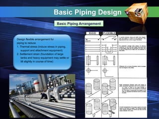
Design flexible arrangementfor
piping to reduce
1. Thermal stress (induce stress in piping,
support and attachment equipment)
2. Settlement strain (foundation of large
tanks and heavy equipment may settle or
tilt slightly in course of time)
Basic Piping Design
Basic Piping Arrangement
37.
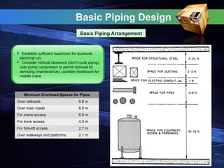
Establish sufficientheadroom for ductwork,
electrical run.
Consider vertical clearance (don’t route piping)
over pump compressor to permit removal for
servicing (maintenance), consider headroom for
mobile crane
Basic Piping Design
Basic Piping Arrangement
Minimum Overhead Spaces for Pipes
Over railroads 6.8 m
Over main roads 6.0 m
For crane access 6.0 m
For truck access 4.0 m
For fork-lift access 2.7 m
Over walkways and platforms 2.1 m
Basic Piping Design
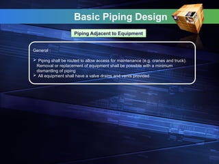
PipingAdjacent to Equipment
General :
Piping shall be routed to allow access for maintenance (e.g. cranes and truck).
Removal or replacement of equipment shall be possible with a minimum
dismantling of piping
All equipment shall have a valve drains and vents provided
40.
Basic Piping Design
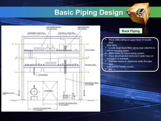
Place utility piping on upper lever of double-
deck
pipe racks
Locate large liquid-filled piping near columns to
reduce bending stress
Allow space for future piping system
Place electrical and instrument cable trays on
outriggers or brackets
Maintain minimum clearance under the pipe
rack
sufficient for mobile cranes
Etc.
Rack Piping
41.
Basic Piping Design
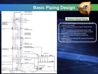
PressureVessel Piping
For tall vertical vessels, the piping will be supported
directly of the vessels
For economy and ease of support, piping should
drop
or rise immediately upon leaving the tower nozzle
and run parallel along the side of the vessel as close
as possible to limit wind-imposed loading
Thermal flexibility will need to consider the
differential
thermal expansion between the vessel and the piping
being supported
Etc.
42.
Basic Piping Design
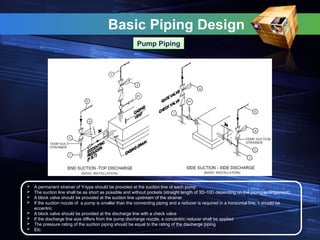
A permanent strainer of Y-type should be provided at the suction line of each pump
The suction line shall be as short as possible and without pockets (straight length of 3D-10D depending on the piping arrangement)
A block valve should be provided at the suction line upstream of the strainer
If the suction nozzle of a pump is smaller than the connecting piping and a reducer is required in a horizontal line, it should be
eccentric
A block valve should be provided at the discharge line with a check valve
If the discharge line size differs from the pump discharge nozzle, a concentric reducer shall be applied
The pressure rating of the suction piping should be equal to the rating of the discharge piping
Etc.
Pump Piping
43.
Basic Piping Design
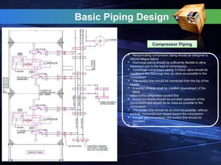
CompressorPiping
Reciprocating compressor piping should be designed to
reduce fatigue failure
Discharge piping should be sufficiently flexible to allow
expansion due to the heat of compression
Centrifugal compressor piping, a check valve should be
installed in the discharge line, as close as possible to the
compressor
The suction line should be connected from the top of the
header
A suction strainer shall be installed downstream of the
block
valve of the compressor suction line
Knock-out drums should be provided upstream of the
compressor and should be as close as possible to the
compressor
The suction line should be as short as possible, without
pockets, horizontal and sloped toward the compressor
For wet gas compressor, the suction line should be
insulated
Etc.
44.
Basic Piping Design
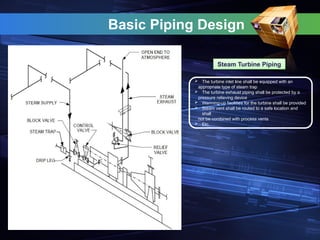
SteamTurbine Piping
The turbine inlet line shall be equipped with an
appropriate type of steam trap
The turbine exhaust piping shall be protected by a
pressure relieving device
Warming-up facilities for the turbine shall be provided
Steam vent shall be routed to a safe location and
shall
not be combined with process vents
Etc.
45.
Basic Piping Design
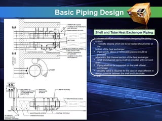
Shelland Tube Heat Exchanger Piping
Access shall be considered when designing the piping
system
Typically, steams which are to be heated should enter at
the
bottom of the heat exchanger
Pipe spools, elbow or removable pieces should be
provided
adjacent to the channel section of the heat exchanger
Shell and channel piping shall be provided with vent and
drain
Piping shall not be supported on the shell of heat
exchanger
A safety valve is required for the case of large different in
design pressure between the shell and tube sides
Etc.
46.
Basic Piping Design
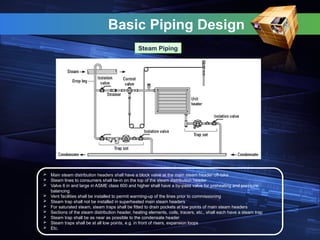
SteamPiping
Main steam distribution headers shall have a block valve at the main steam header off-take
Steam lines to consumers shall tie-in on the top of the steam distribution header
Valve 6 in and large in ASME class 600 and higher shall have a by-pass valve for preheating and pressure
balancing
Vent facilities shall be installed to permit warming-up of the lines prior to commissioning
Steam trap shall not be installed in superheated main steam headers
For saturated steam, steam traps shall be fitted to drain pockets at low points of main steam headers
Sections of the steam distribution header, heating elements, coils, tracers, etc., shall each have a steam trap
Steam trap shall be as near as possible to the condensate header
Steam traps shall be at all low points, e.g. in front of risers, expansion loops
Etc.
47.
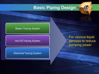
Steam Tracing System
HotOil Tracing System
Electrical Tracing System
For viscous liquid
services to reduce
pumping power
Basic Piping Design
48.
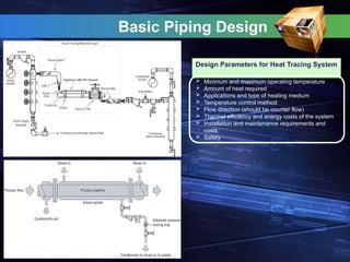
Design Parameters forHeat Tracing System
Minimum and maximum operating temperature
Amount of heat required
Applications and type of heating medium
Temperature control method
Flow direction (should be counter flow)
Thermal efficiency and energy costs of the system
Installation and maintenance requirements and
costs
Safety
Basic Piping Design
49.
Basic Piping Design
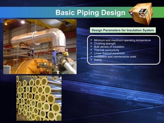
DesignParameters for Insulation System
Minimum and maximum operating temperature
Crushing strength
Bulk density of insulation
Thermal conductivity
Linear thermal expansion
Installation and maintenance costs
Safety
50.
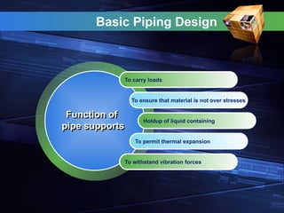
To carry loads
Toensure that material is not over stresses
Holdup of liquid containing
To permit thermal expansion
To withstand vibration forces
Function of
pipe supports
Basic Piping Design
51.
Weight load
Available attachmentclearance
Available of structural steel
Direction of loads and movement
Design temperature
Selection of
pipe supports
Basic Piping Design
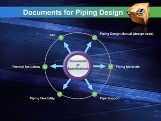
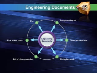
Piping Design Manual(design code)
Etc.
Piping Materials
Pipe Support
Thermal Insulation
Piping Flexibility
Documents
or
Specifications
Documents for Piping Design
54.
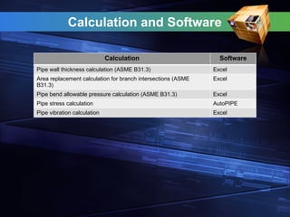
Calculation and Software
CalculationSoftware
Pipe wall thickness calculation (ASME B31.3) Excel
Area replacement calculation for branch intersections (ASME
B31.3)
Excel
Pipe bend allowable pressure calculation (ASME B31.3) Excel
Pipe stress calculation AutoPIPE
Pipe vibration calculation Excel
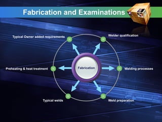
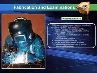
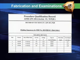
Fabrication and Examinations
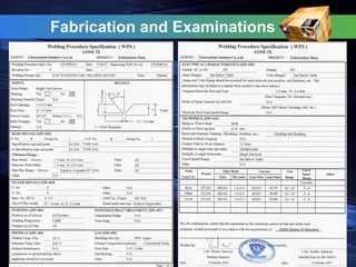
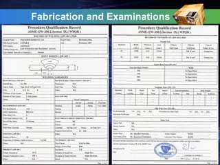
WelderQualification
Welders are required to use an approved procedure in
accordance with B&PV code section IX
Welding Procedure Specification (WPS)
Procedure Qualification Record (PQR), which is
retained by the employer
Welders are required to be qualified by test in
accordance
with B&PV code section IX
Performance Qualifications Test
The test record is documented as Welder
Performance Qualification (WPQ), which is
retained by the employer
58.
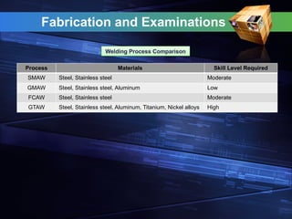
Fabrication and Examinations
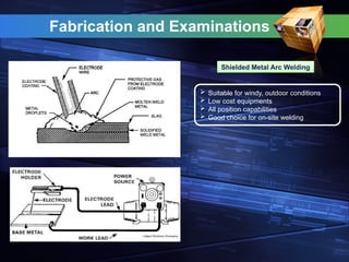
ShieldedMetal Arc Welding
Suitable for windy, outdoor conditions
Low cost equipments
All position capabilities
Good choice for on-site welding
59.
Fabrication and Examinations
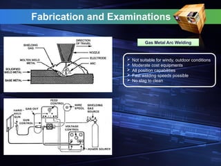
GasMetal Arc Welding
Not suitable for windy, outdoor conditions
Moderate cost equipments
All position capabilities
Fast welding speeds possible
No slag to clean
60.
Fabrication and Examinations
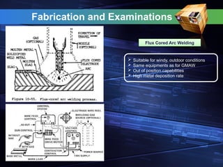
FluxCored Arc Welding
Suitable for windy, outdoor conditions
Same equipments as for GMAW
Out of position capabilities
High metal deposition rate
61.
Fabrication and Examinations
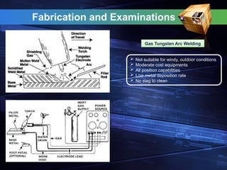
GasTungsten Arc Welding
Not suitable for windy, outdoor conditions
Moderate cost equipments
All position capabilities
Low metal deposition rate
No slag to clean
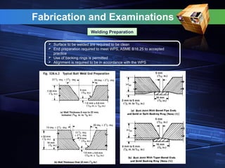
Fabrication and Examinations
WeldingPreparation
Surface to be welded are required to be clean
End preparation required to meet WPS, ASME B16.25 to accepted
practice
Use of backing rings is permitted
Alignment is required to be in accordance with the WPS
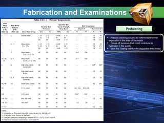
Fabrication and Examinations
Preheating
Prevent cracking caused by differential thermal
expansion in the area of the welds
Drives off moisture that cloud contribute to
hydrogen in the welds
Slow the cooling rate for the deposited weld metal
66.
Fabrication and Examinations
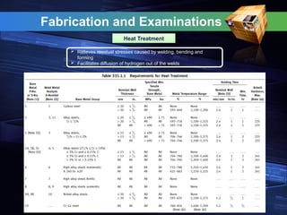
HeatTreatment
Relieves residual stresses caused by welding, bending and
forming
Facilitates diffusion of hydrogen out of the welds
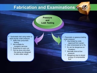
Hydrostatic testusing water or
other liquids under pressure
Safer than pneumatic
testing
Not suitable for
cryogenic services
Expansive to carry out
Can be done only when
the piping are designed
to take water weight
Pressure
and
Leak Testing
Pneumatic or gaseous testing
under pressure
Use limited by code
(approval from owner)
Use compressed air or N2
N2 can be dangerous on
inhalation
Normally done at low
pressure
Dangerous due to stored
energy of compressible
fluid
Fabrication and Examinations
72.
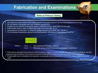
Fabrication and Examinations
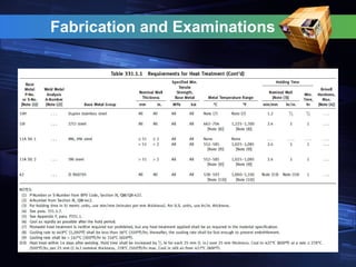
Ruleson Pressure Testing
Use water as a test medium and holding period 10 minutes minimum (do not hold pressure for too long)
Do not perform hydrostatic test near transition temperature
If water can be harmful to the piping system (refractory lining), other fluids can be used
If flammable liquid is used, its flash point shall not be less than 50 o
C
Use pressure not less than 1.5 times the design pressure (for ASME Sec. VIII Div.1)
For the design temperature above the test temperature, the minimum test pressure shall be:
Where PT,P = Test pressure and design pressure
ST,S = Allowable stress at test temperature and design temperature
If the above calculated test pressure would produce a stress in excess the yield strength at test temperature, the test
pressure may be reduce to the maximum pressure that will not excess the yield strength at test temperature
If hydrostatic test is considered not practical, a pneumatic test at pressure of 110% of the design pressure can be
used
S
S
P
P T
T 5
.
1

![Definition
Piping:
…assemblies of piping components used…[for] fluid flows. Piping also
includes pipe supporting elements, but does not include support structures…
or equipment…
Piping system:
…interconnected piping subject to the same design conditions
Piping components:
…mechanical elements suitable for joining or assembly into pressure tight
fluid-containing piping systems…pipes, fittings, flanges, gaskets, bolting,
valves and special devices such as expansion joints.](https://image.slidesharecdn.com/pipingdesignbasic-250718014937-02262ce9/85/Piping-Design-Basic-course-for-engineer-study-4-320.jpg)
![Codes & Standards for Piping
Scope of ASME B31.3
Rules for the Process Piping Code Section B31.3 have been developed considering piping
typically found in petroleum refineries; chemical, pharmaceutical, textile, paper, semiconductor,
and cryogenic plants; and related processing plants and terminals. [300.1]
This Code applies for all fluids including:
Row, intermediate and finished chemicals
Petroleum products
Gas, steam, air and water
Fluidized solids
Refrigerants
Cryogenic fluids
This Code excludes the following:
Piping systems designed for internal gage pressures at or above zero but less than 105
kPa (15 psi)
Fluid handled is nonflammable, nontoxic, and not damaging to human tissues
Power boilers in accordance with BPV Code Section I and boiler external piping which is
required to conform to B31.1
Tube headers and manifolds of fired heaters
Pressure vessels, heat exchangers, pumps, compressors and processing equipment,
including internal piping and connections for external piping](https://image.slidesharecdn.com/pipingdesignbasic-250718014937-02262ce9/85/Piping-Design-Basic-course-for-engineer-study-8-320.jpg)