Download as PDF, PPTX


![Sample Problem 2 - Solution
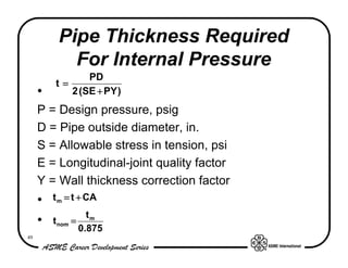
PD
t=
2(SE + PY )
1,380 × 14
t=
2[(16,200 × 1) + (1,380 × 0.4 )]
t = 0.577 in.
54](https://image.slidesharecdn.com/asmeprocessplantpipingoverview-120919024114-phpapp01/85/Simple-Piping-design-54-320.jpg)
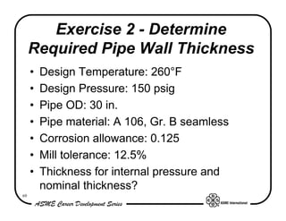
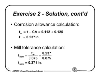
![Exercise 2 - Solution
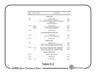
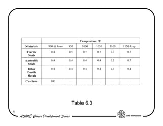
• From Tables 6.1, 6.2, and 6.3 obtain values:
– S = 20,000 psi
– E = 1.0
– Y = 0.4
• Thickness calculation:
PD 150 × 30
t= =
2(SE + PY ) 2[(20,000 × 1.0 ) + (150 × 0.04 )]
t = 0.112 in.
70](https://image.slidesharecdn.com/asmeprocessplantpipingoverview-120919024114-phpapp01/85/Simple-Piping-design-70-320.jpg)


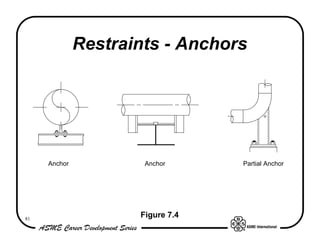
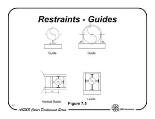
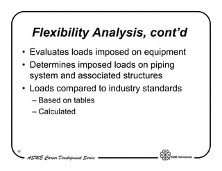
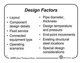
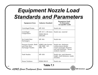
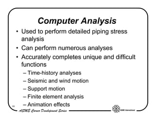
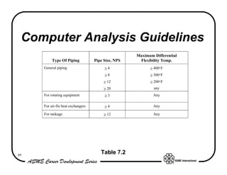
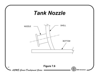
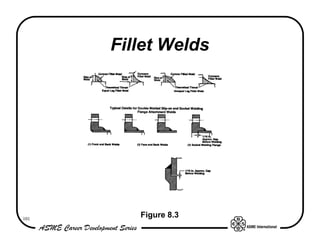


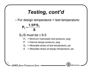

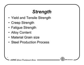
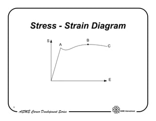
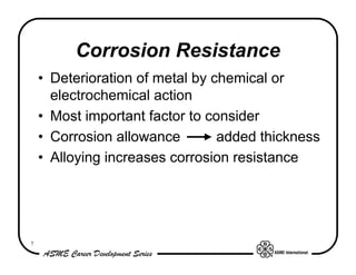
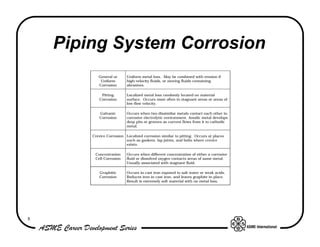
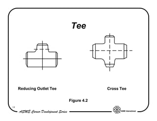
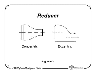
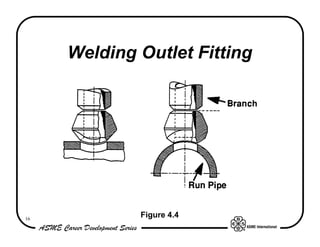
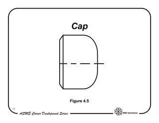
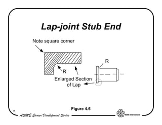
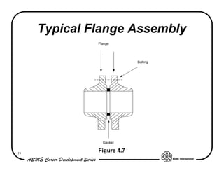
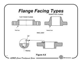
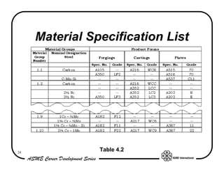
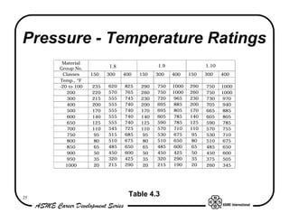
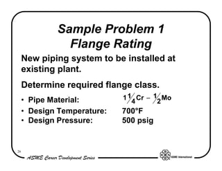
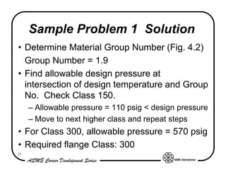
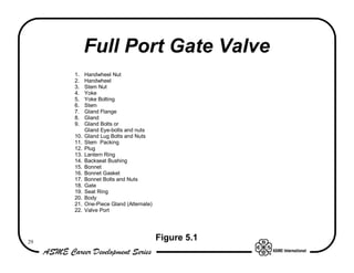
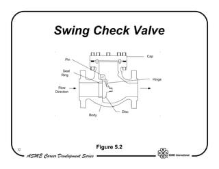
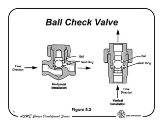
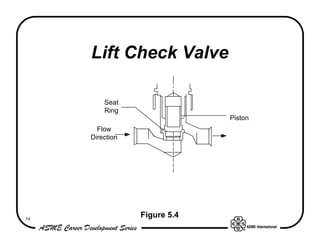
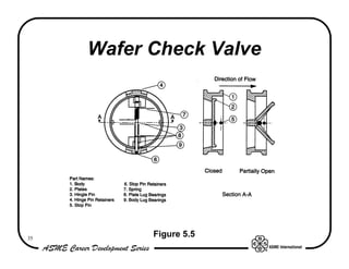
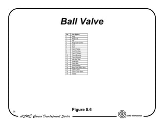
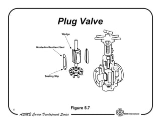
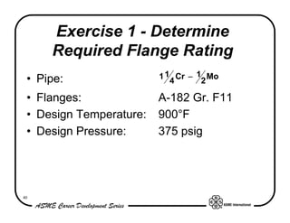
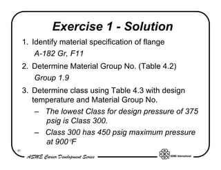
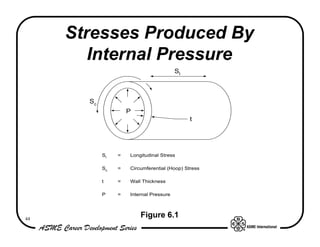
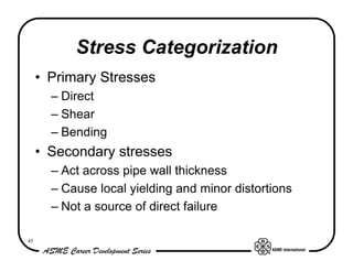
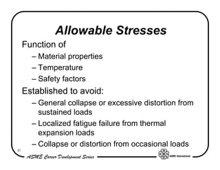
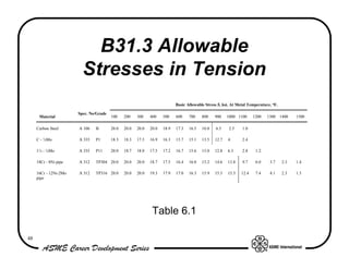
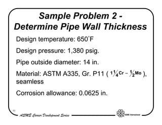
The document provides an overview of process plant piping system design. It discusses key components of piping systems including pipe, fittings, flanges, gaskets, bolting, valves and supports. It describes design requirements according to the ASME B31.3 code and considerations for material selection such as strength, corrosion resistance, toughness and cost. Examples of stress analysis, flange rating determination and valve selection are also provided.


![Protech presentation [new]](https://cdn.slidesharecdn.com/ss_thumbnails/protechpresentationnew-150421032547-conversion-gate01-thumbnail.jpg?width=640&height=640&fit=bounds)


