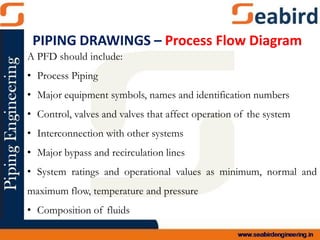
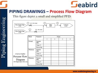
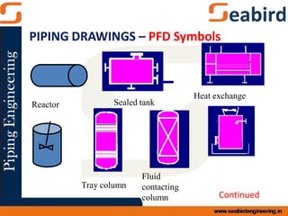
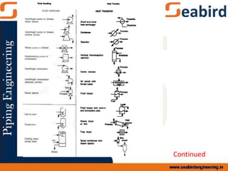
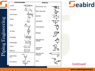
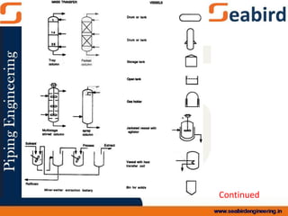
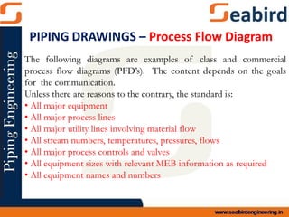
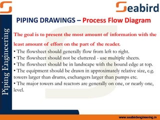
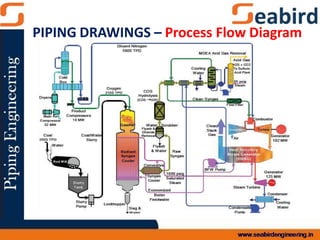
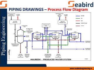
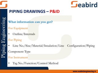
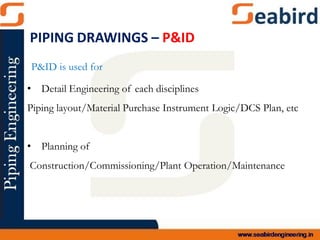
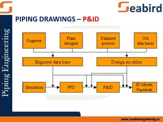
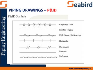
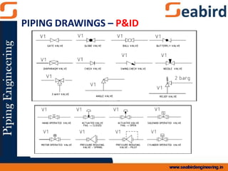
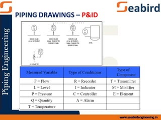
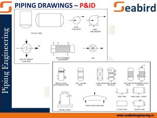
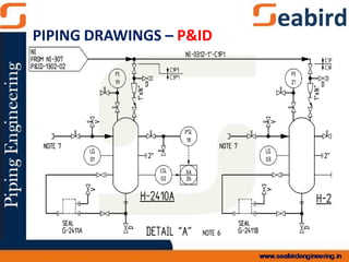
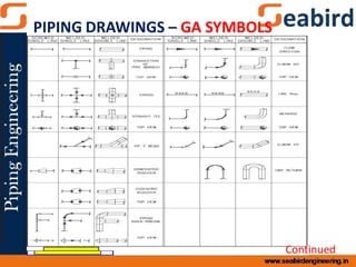
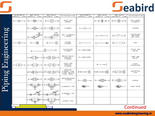
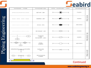
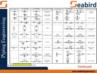
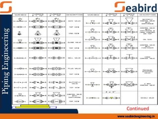
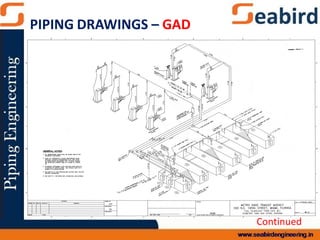
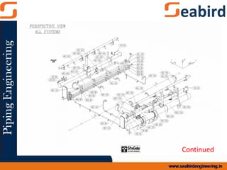
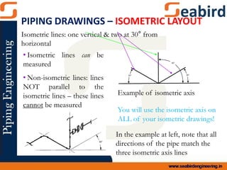
This document provides information on various piping drawings used in piping design and installation. It discusses process flow diagrams (PFDs), piping and instrumentation diagrams (P&IDs), piping isometrics, plot plans, and general arrangement drawings. PFDs show the major equipment and process flows at a high level, while P&IDs provide more detailed piping information along with instrumentation and control schemes. Piping isometrics are used for fabrication and show piping runs at an angle for clarity. General arrangement drawings indicate equipment locations and piping layouts from a plan view. Together these drawings provide the necessary information for proper piping system design, installation, and operation.