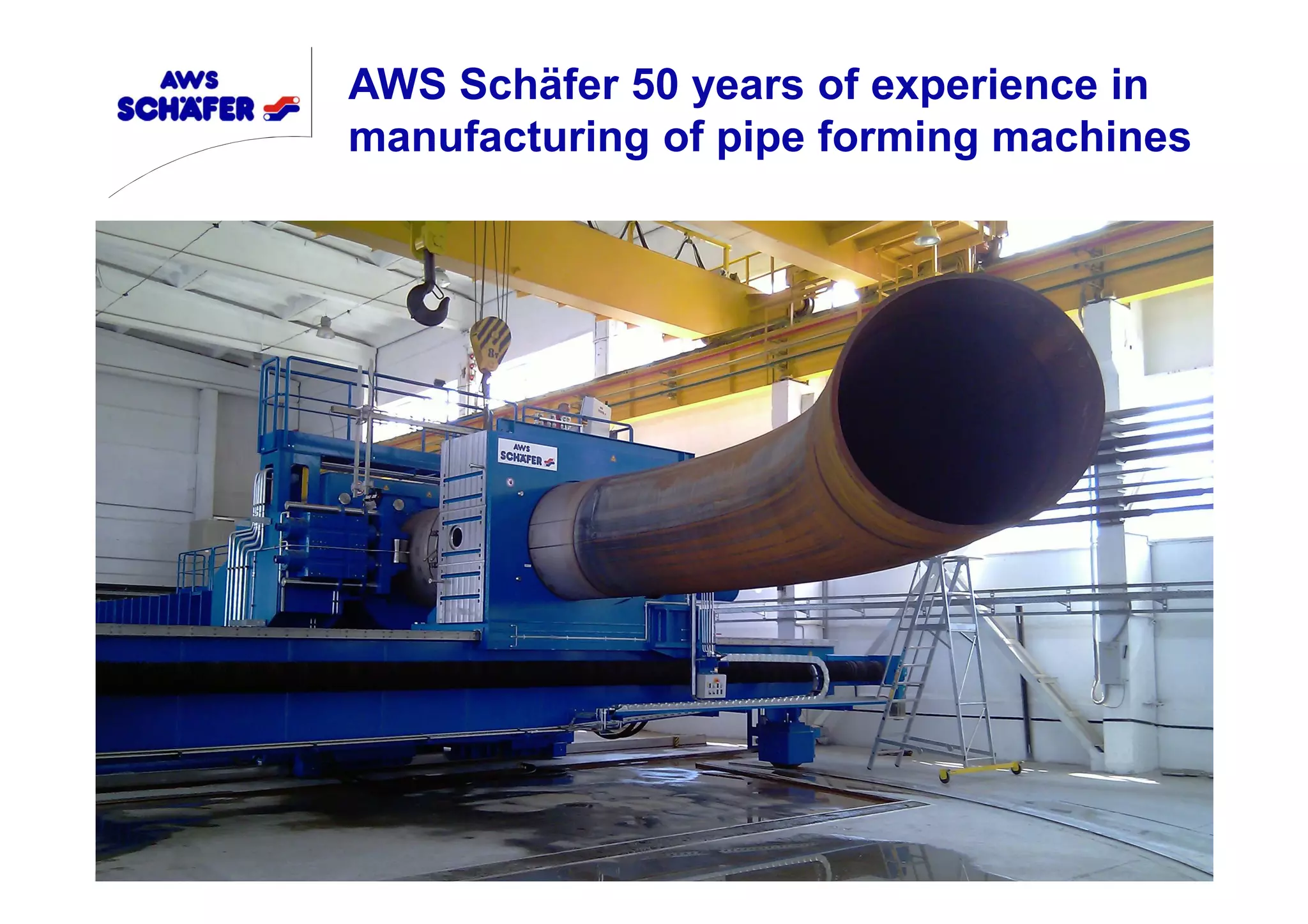
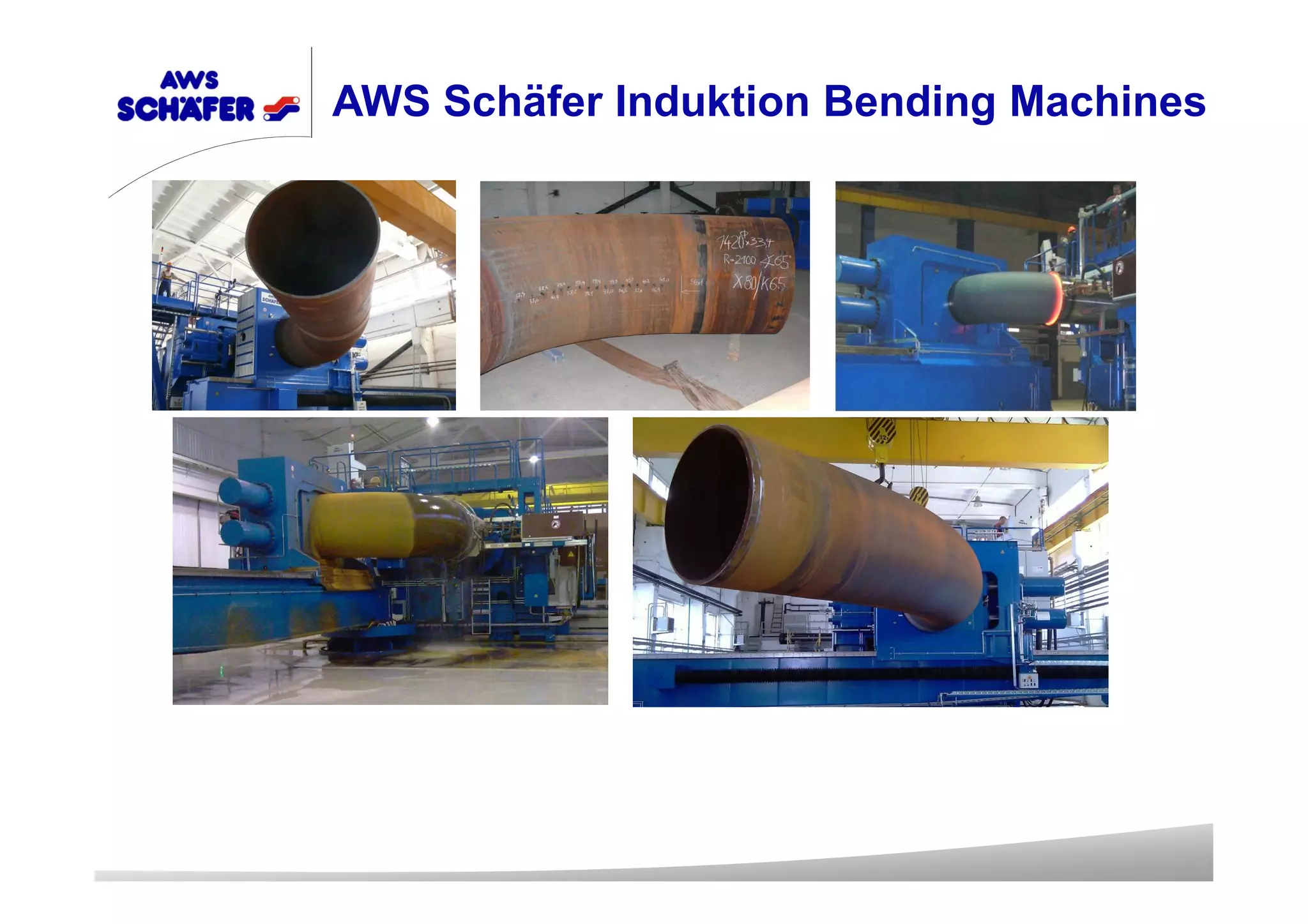
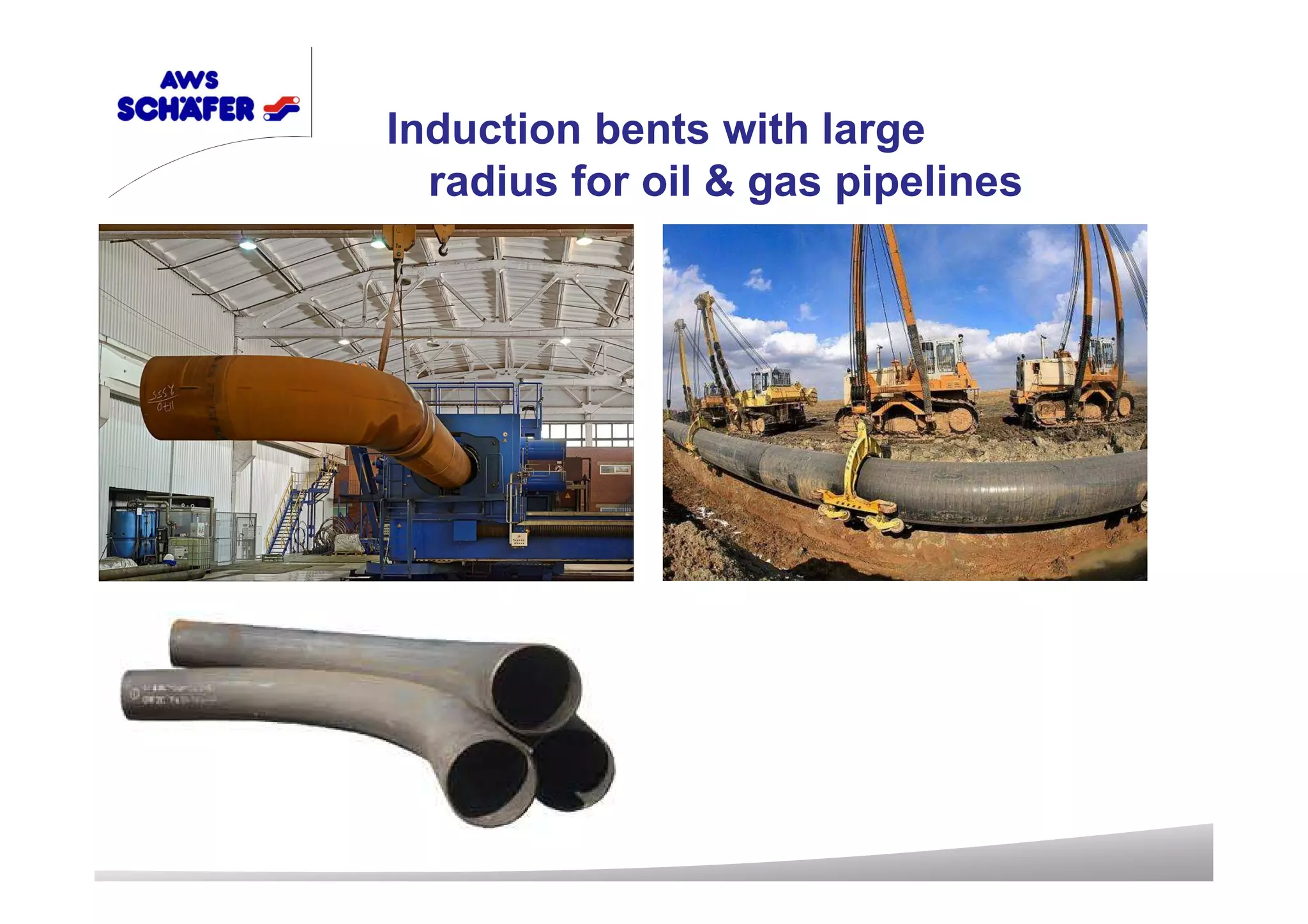
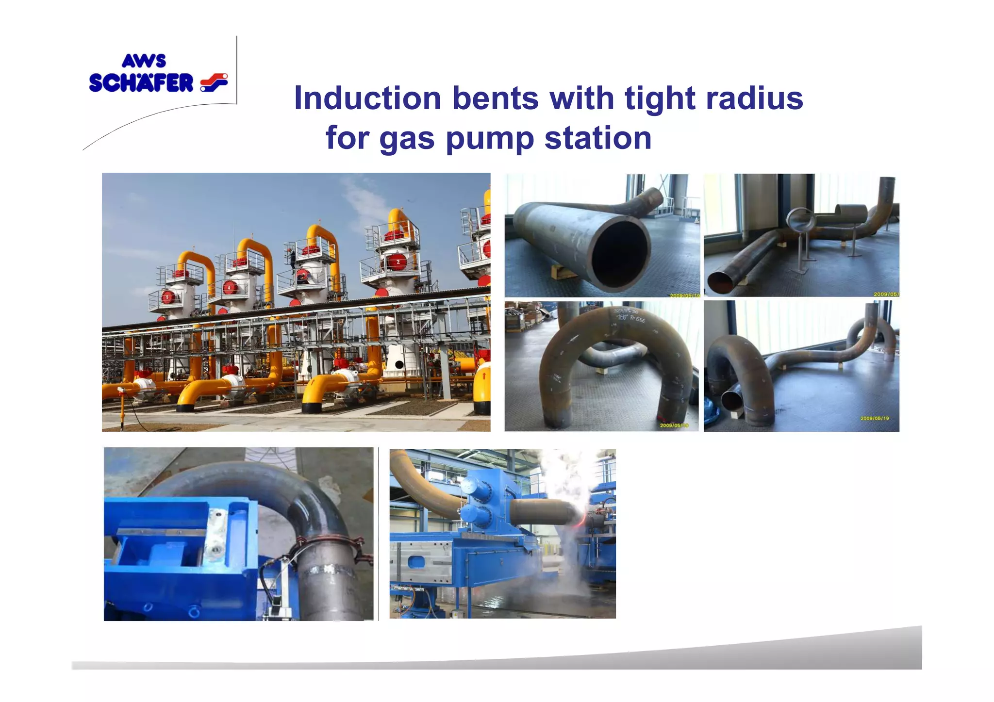
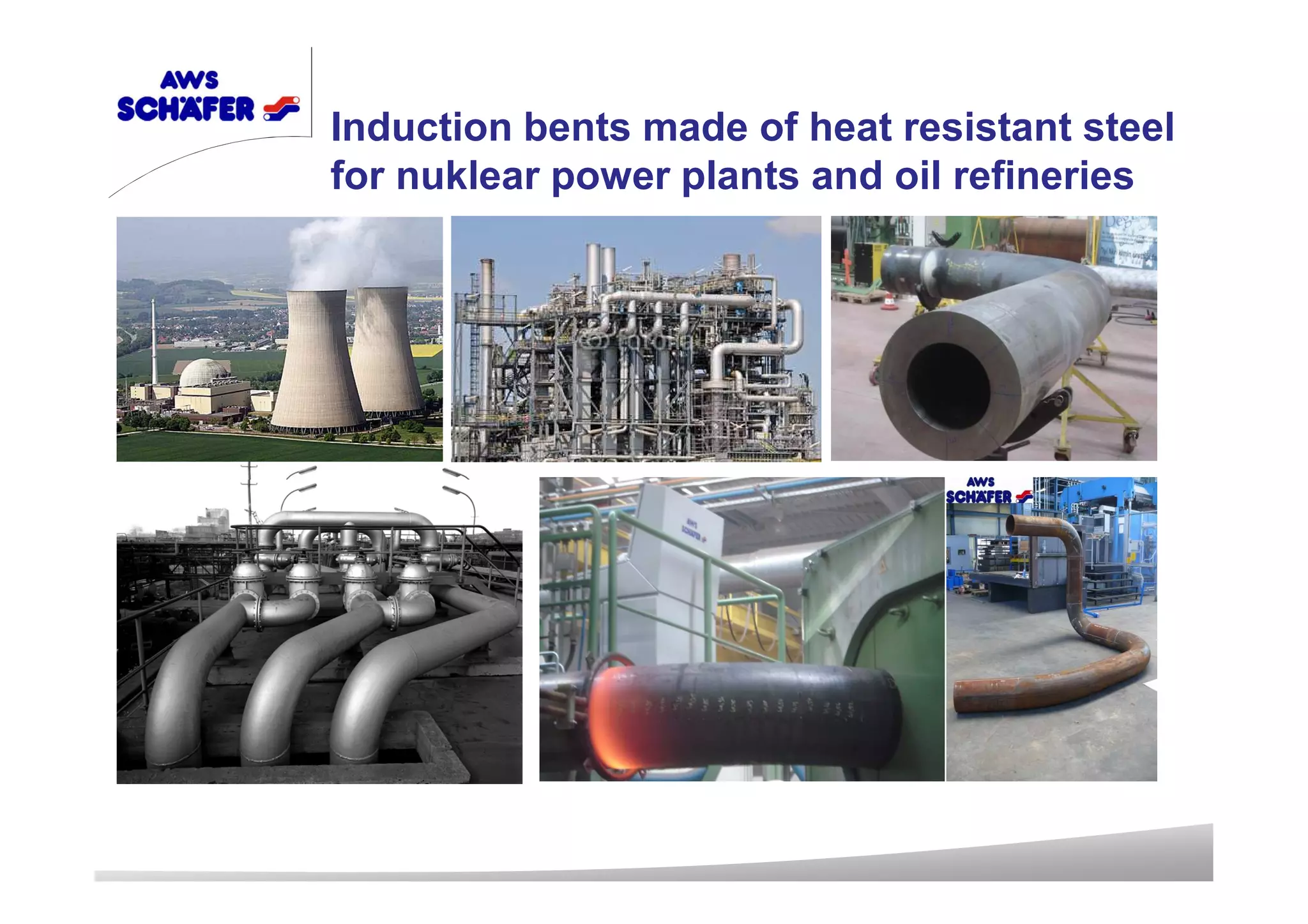
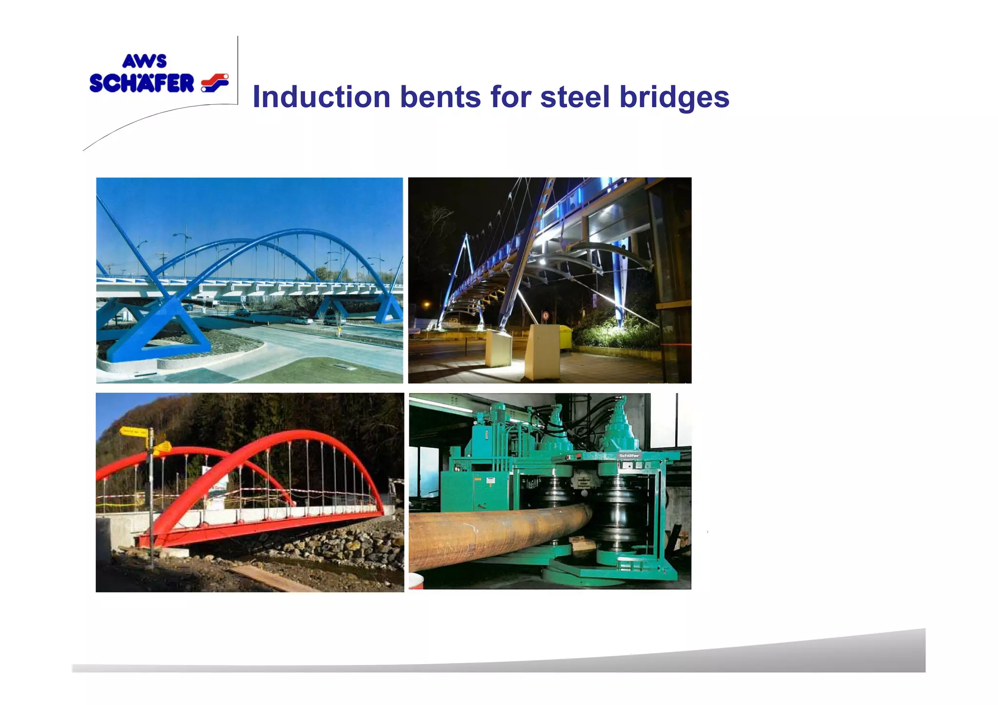
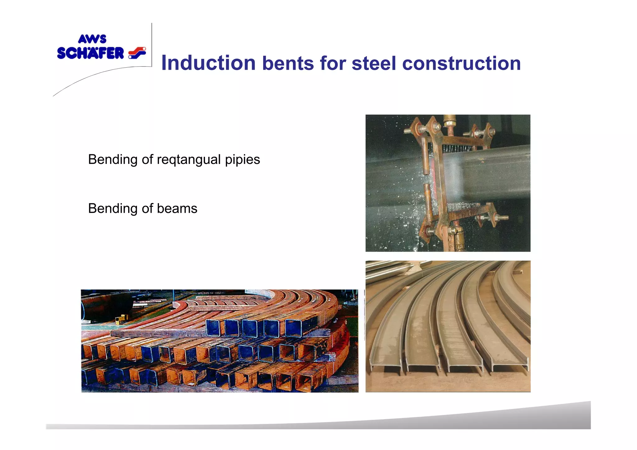
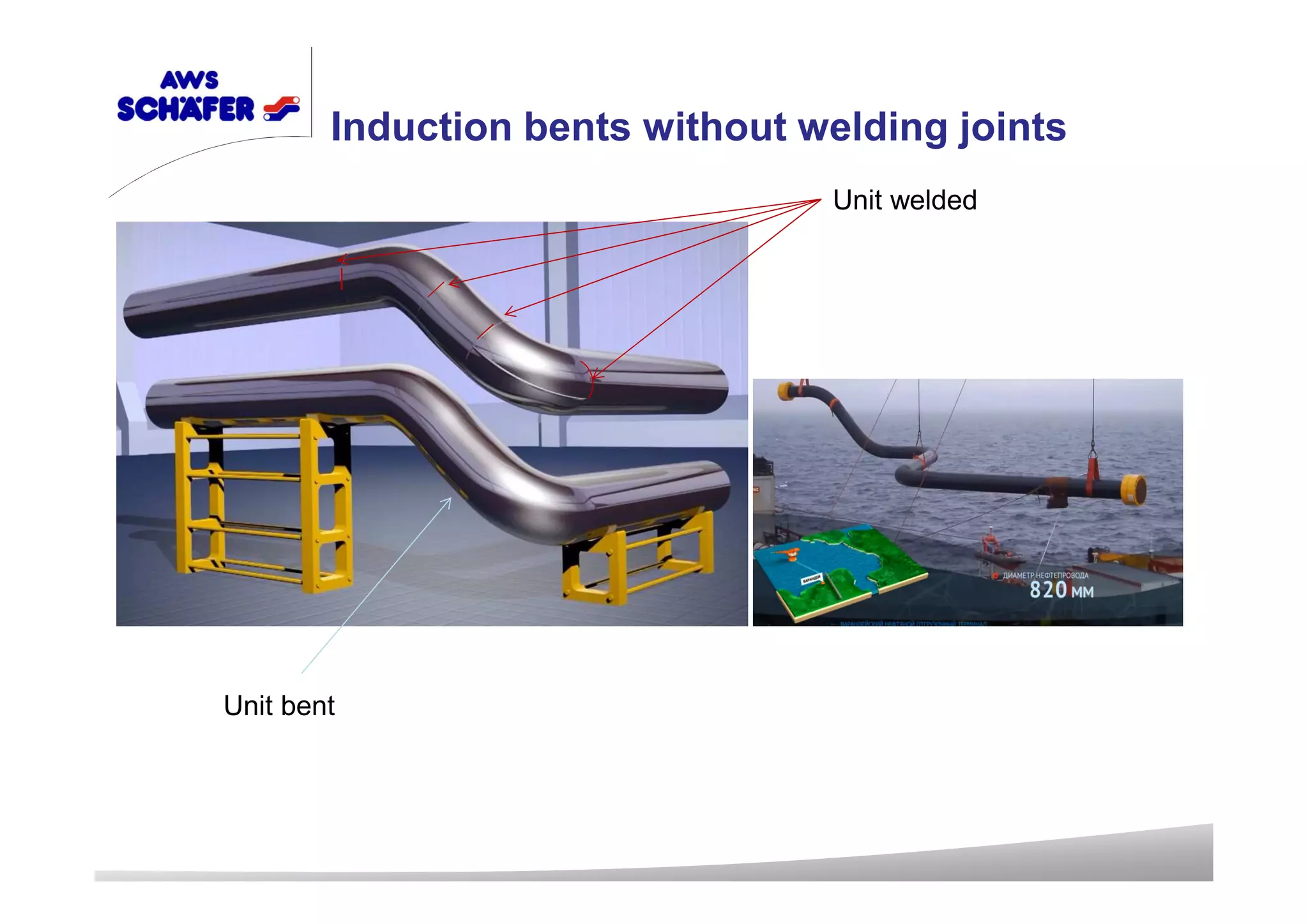
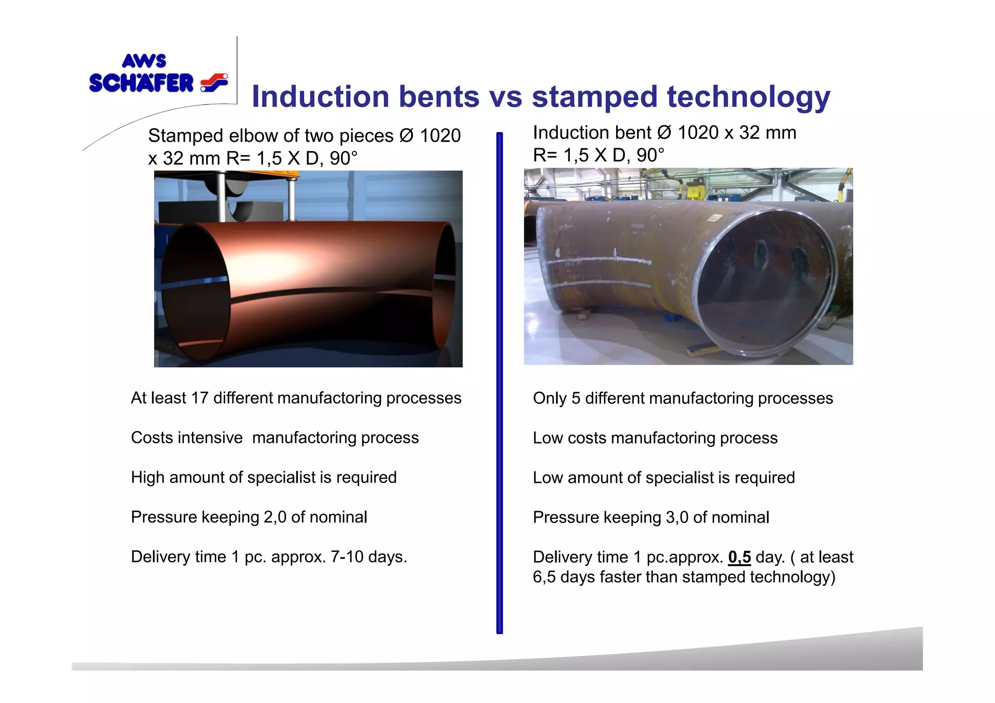
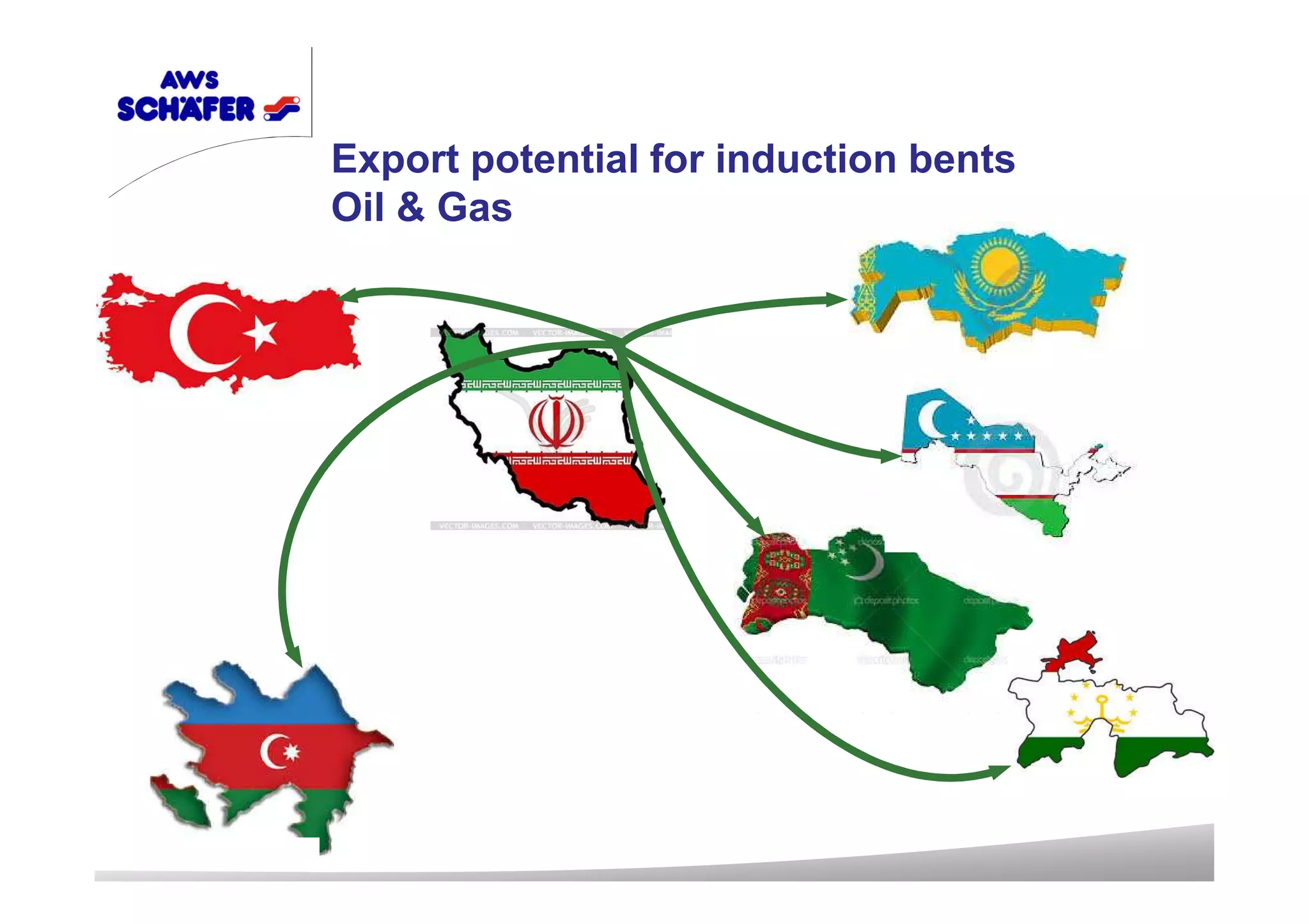
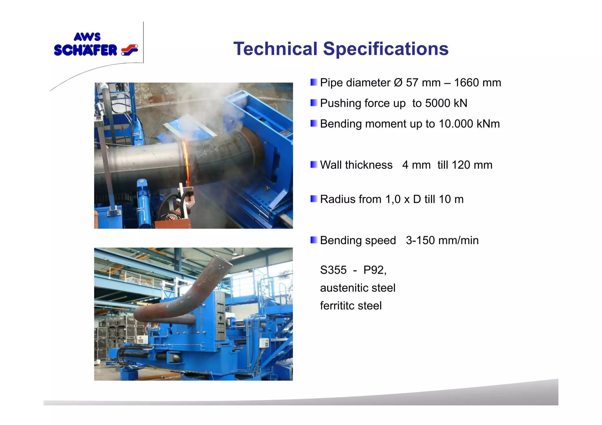
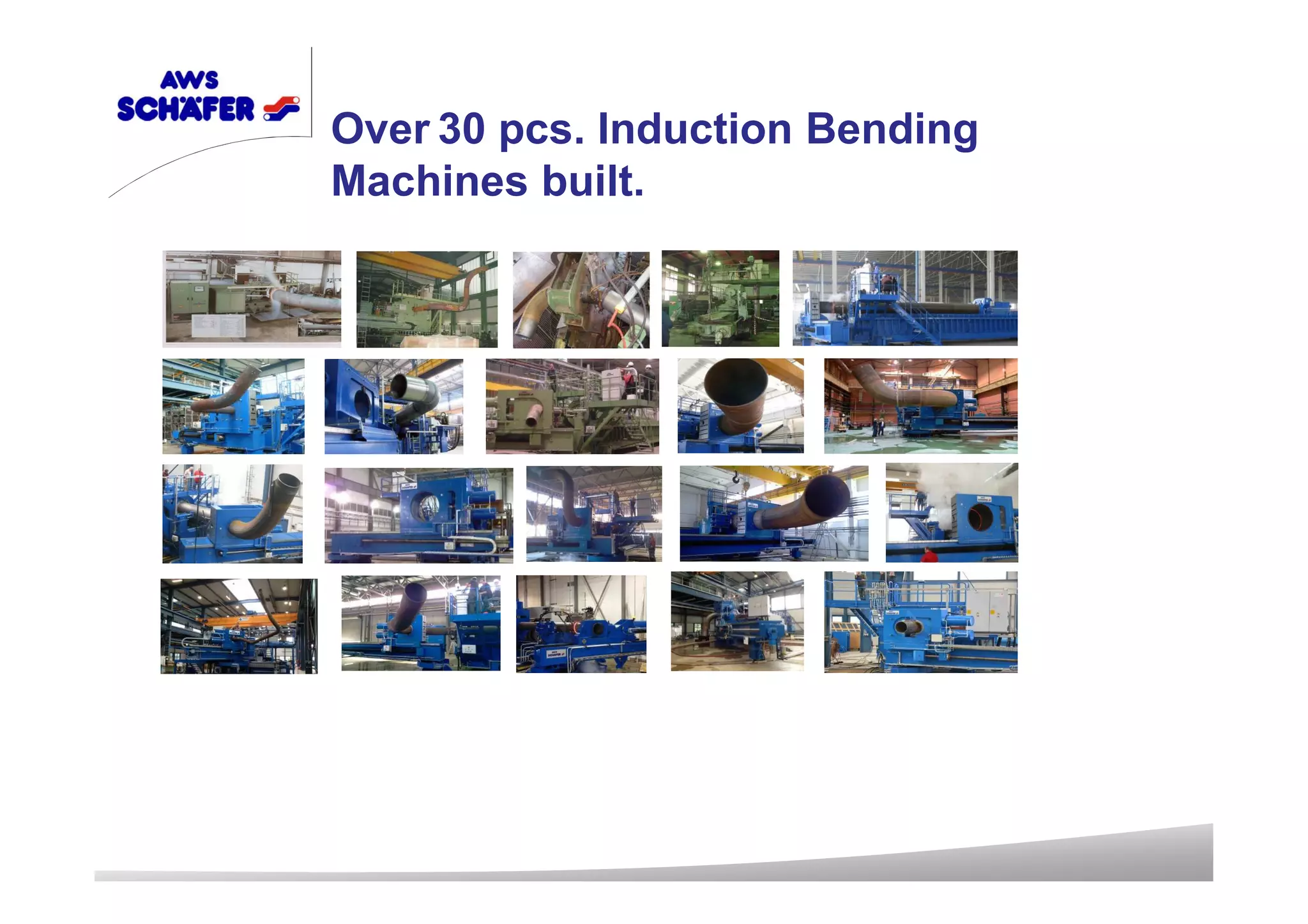
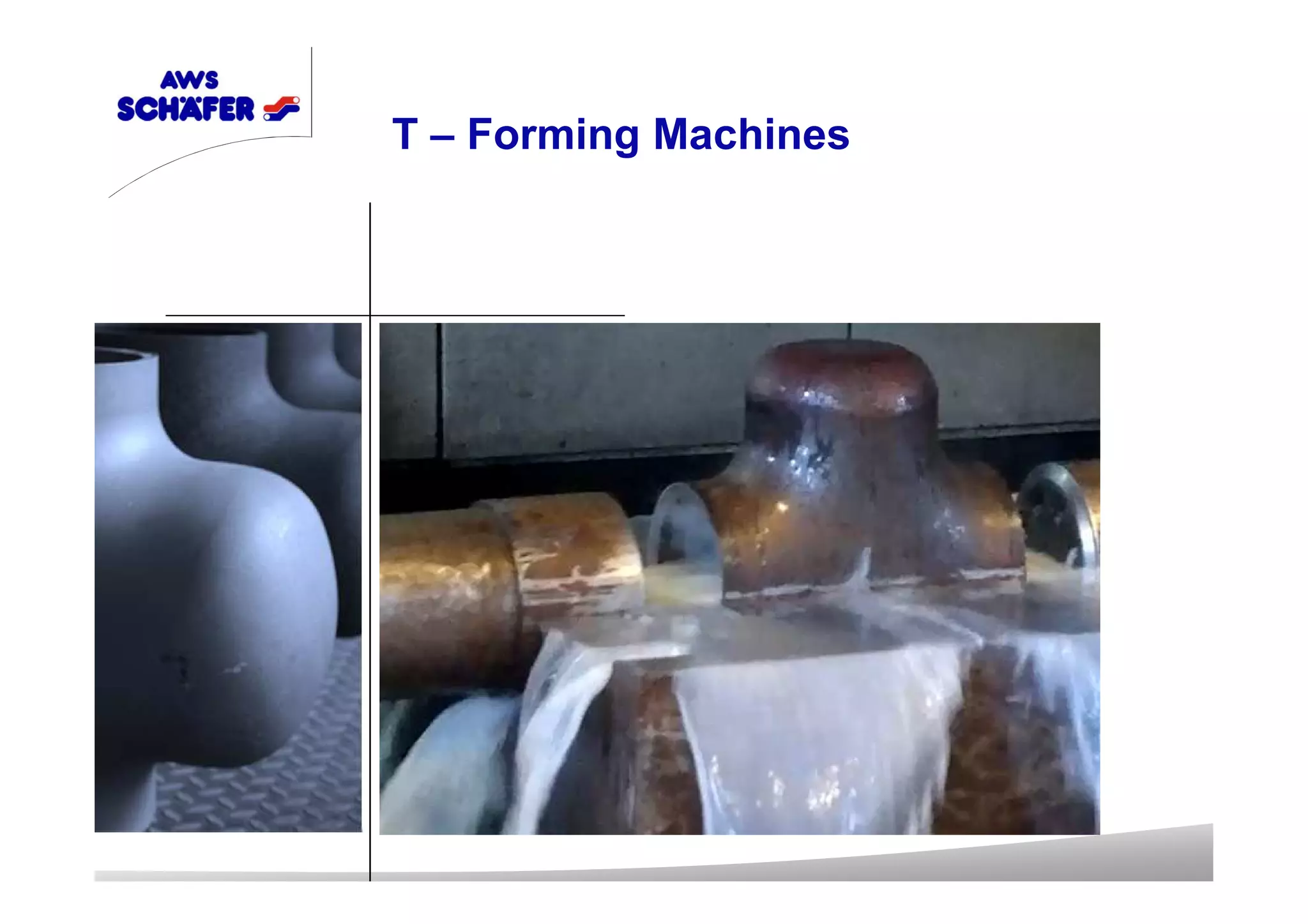
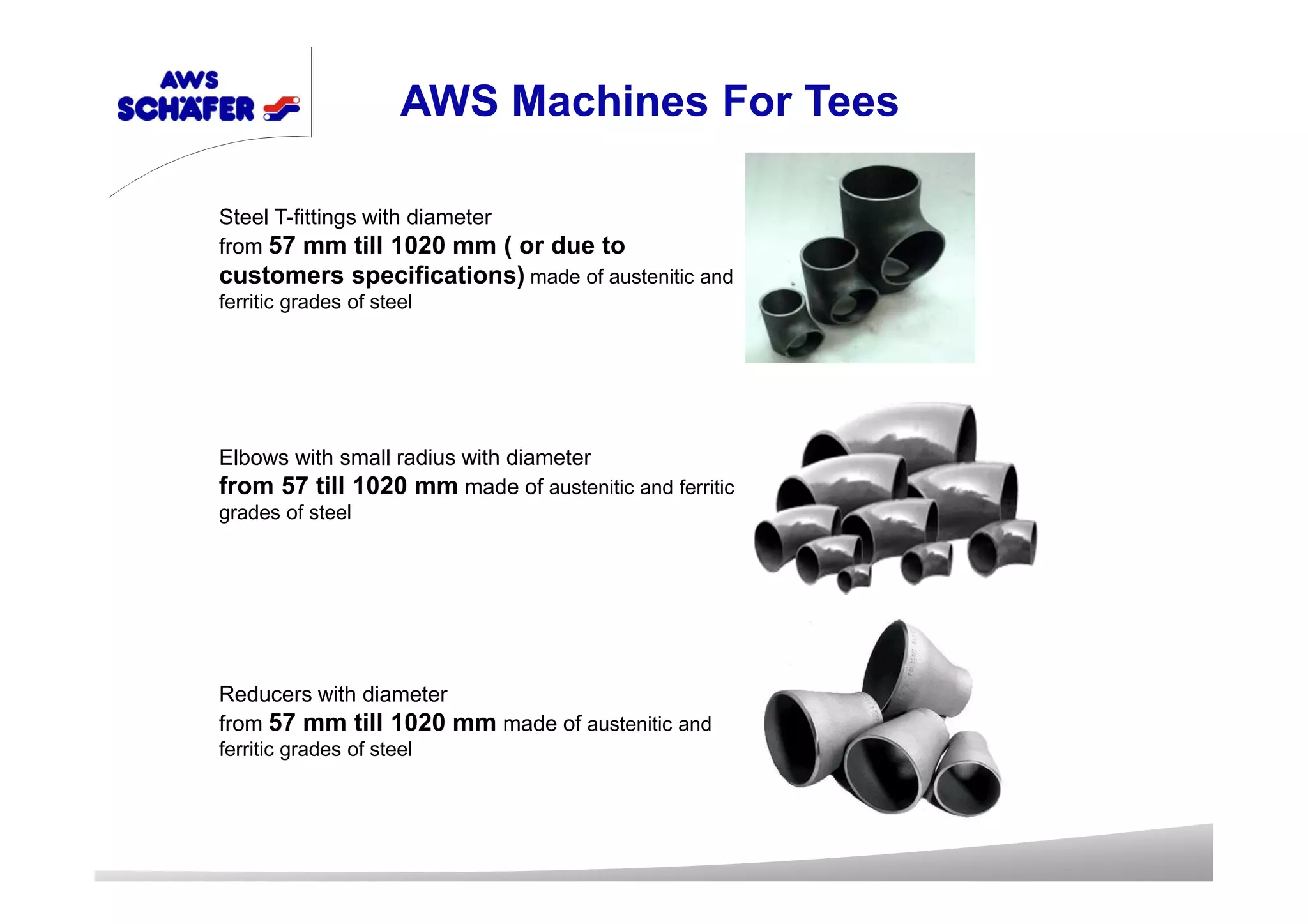
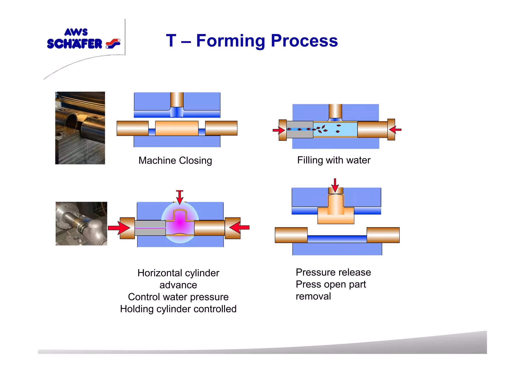
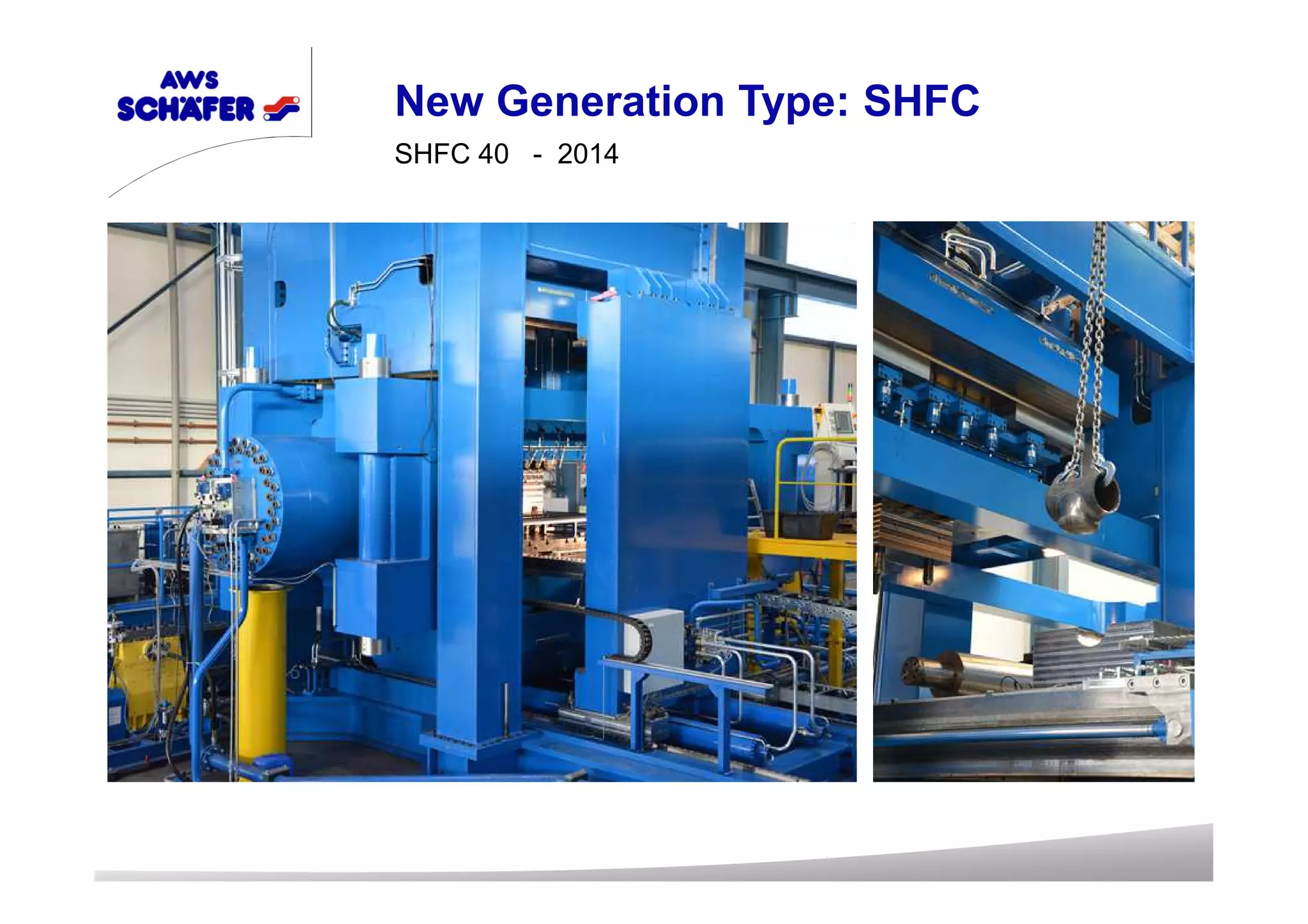
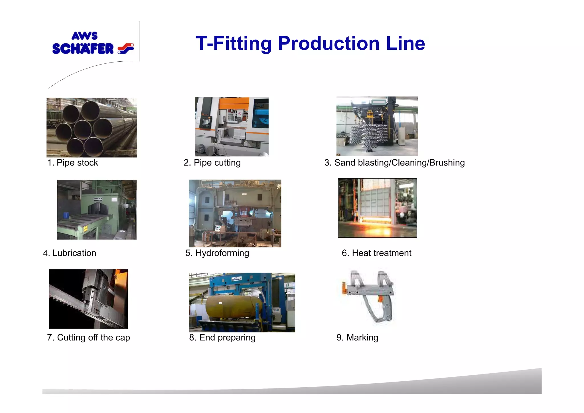
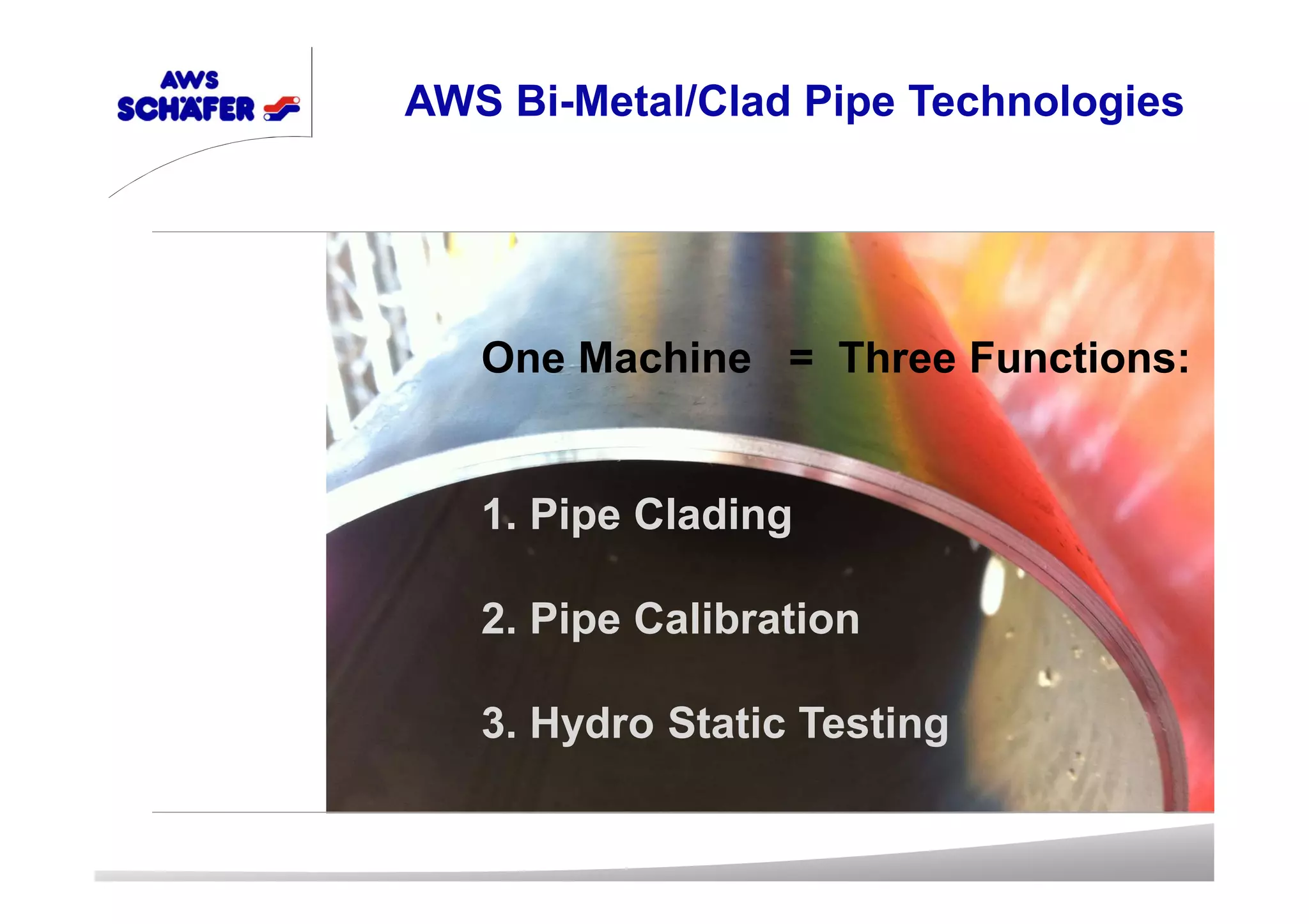
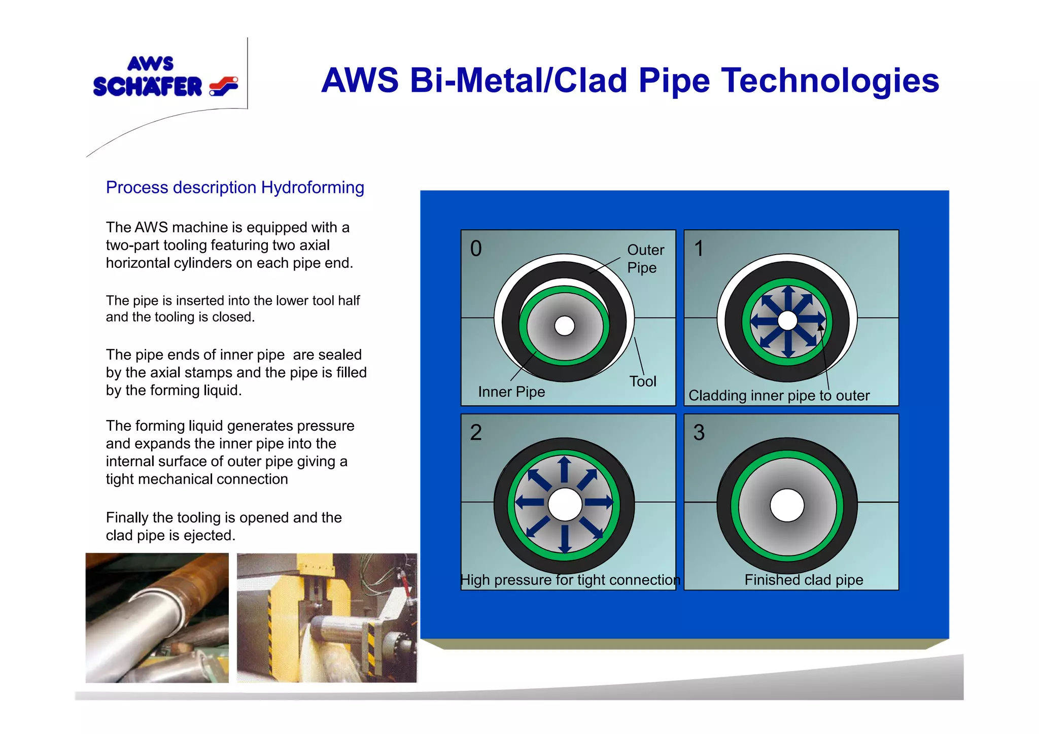
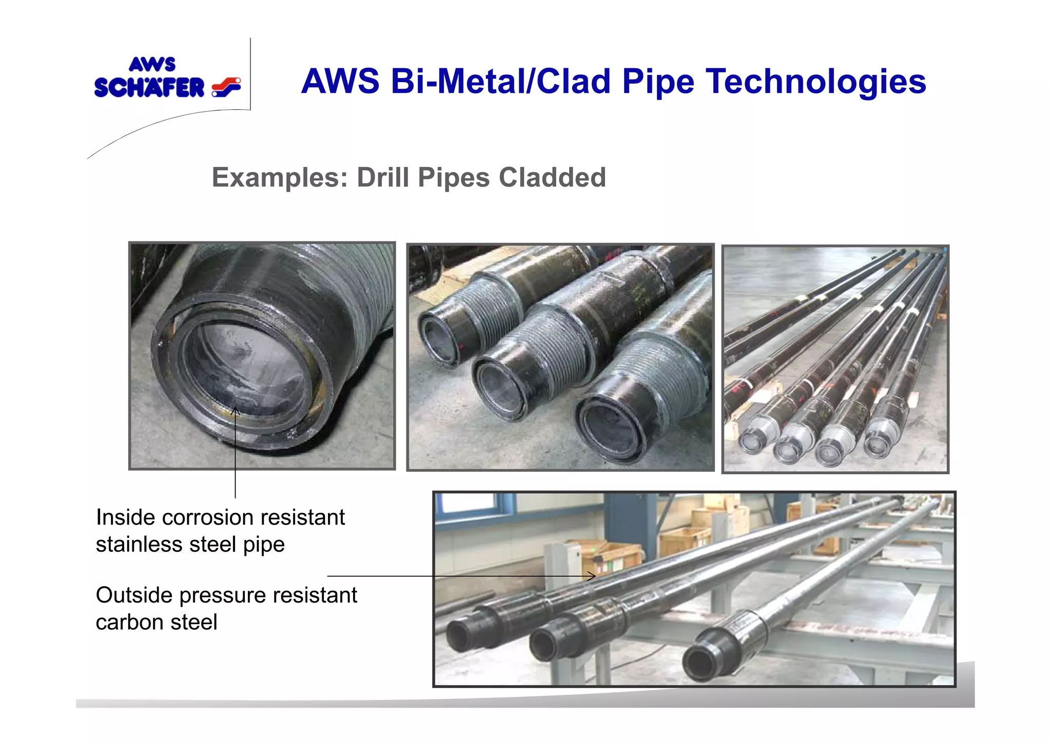
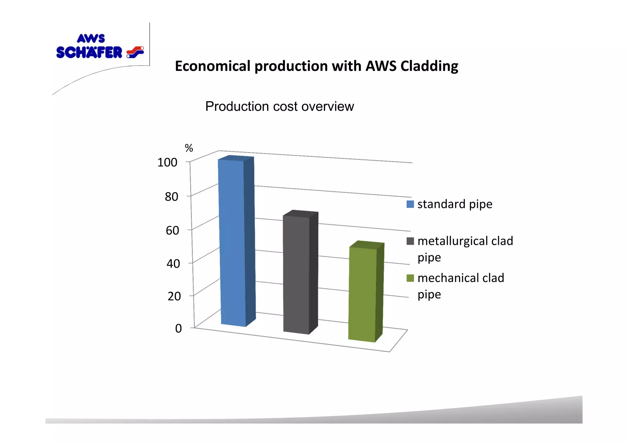
AWS Schäfer 50 years of experience in
manufacturing of pipe forming machines
AWS Schäfer Induktion Bending Machines
• Variable bending radius. The proposed technology enables manufacturing of elbows with
different radiuses within the length of the pipe, including radii less than 1.5 x D, using only
one set of tooling for the same diameter pipes. Bending radius can be anything from 1.5 to
40 DN
• Bending can be performed with preservation of some straight sections
length both before bending area and behind, as well as in between. It
reduces the number of welds in the system and prevents welding on
critical points (tangential), which can not be avoided in the manufacture of assembly
welding units
• High quality of elbow, low wall thinning and ovality, high performance
• Minimal required set of tools does not require large amounts of the expensive stamping
equipment as in the manufacture of stamped elbows.
• CNC system based on an industrial PC in combination with Hydraulic power and thanks to
a special algorithm of coordinated movements of the inductor and the pipes for great
quality with minimal human intervention
The advantage of the induction
bending
Induction bents with large
radius for oil & gas pipelines
Induction bents with tight radius
for gas pump station
Induction bents made of heat resistant steel
for nuklear power plants and oil refineries
Induction bents for steel bridges
Bending of reqtangual pipies
Bending of beams
Induction bents for steel construction
Unit bent
Unit welded
Induction bents without welding joints
Stamped elbow of two pieces Ø 1020
x 32 mm R= 1,5 X D, 90°
Induction bent Ø 1020 x 32 mm
R= 1,5 X D, 90°
At least 17 different manufactoring processes
Costs intensive manufactoring process
High amount of specialist is required
Pressure keeping 2,0 of nominal
Delivery time 1 pc. approx. 7-10 days.
Only 5 different manufactoring processes
Low costs manufactoring process
Low amount of specialist is required
Pressure keeping 3,0 of nominal
Delivery time 1 pc.approx. 0,5 day. ( at least
6,5 days faster than stamped technology)
Induction bents vs stamped technology
Export potential for induction bents
Oil & Gas
Pipe diameter Ø 57 mm – 1660 mm
Pushing force up to 5000 kN
Bending moment up to 10.000 kNm
Wall thickness 4 mm till 120 mm
Radius from 1,0 x D till 10 m
Bending speed 3-150 mm/min
S355 - P92,
austenitic steel
ferrititc steel
Technical Specifications
Over 30 pcs. Induction Bending
Machines built.
T – Forming Machines
Steel T-fittings with diameter
from 57 mm till 1020 mm ( or due to
customers specifications) made of austenitic and
ferritic grades of steel
Elbows with small radius with diameter
from 57 till 1020 mm made of austenitic and ferritic
grades of steel
Reducers with diameter
from 57 mm till 1020 mm made of austenitic and
ferritic grades of steel
AWS Machines For Tees
Machine Closing Filling with water
Horizontal cylinder
advance
Control water pressure
Holding cylinder controlled
Pressure release
Press open part
removal
T – Forming Process
SHFC 40 - 2014
New Generation Type: SHFC
1. Pipe stock 2. Pipe cutting 3. Sand blasting/Cleaning/Brushing
4. Lubrication 5. Hydroforming 6. Heat treatment
7. Cutting off the cap 8. End preparing 9. Marking
T-Fitting Production Line
0
50
100
Most cost effective production method
%
Hotforming
Hydroforming
Cost comparison with hot forming
technology
Advantages of Hydroforming
Proposal for creation of high-efficiency, highly effective and flexible production of
pipeline fittings which guaranties:
Reduction of a work cycle of manufacture of a product - cost price advantage
Increasing mechanical characteristics of a tee at the expense of a cold hardening
and the subsequent heat treatment
High efficiency,
Manufacturing of products according to all standards like DIN, ANSI, Gost
Minimal production time, in comparison with other technologies
100 % repeatability of the sizes and properties of dimensions
Less influence of the human factor on the basic processes, as a consequence of the
high quality output
The minimum requirement of the highly skilled personnel
One Machine = Three Functions:
1. Pipe Clading
2. Pipe Calibration
3. Hydro Static Testing
AWS Bi-Metal/Clad Pipe Technologies
Modern oil production conditions have changed significantly. The
development of new oil fields takes place in the more inaccessible areas
with unfavorable geological and climatic conditions for all kinds of work
(drilling, construction, maintenance of bore hole) and without production and
social infrastructure.
Oil downstream in well-developed regions is associated with other
complications: most of the bore holes are open to 20-40 years ago,
characterized by a decrease in production rate, high water content and
increased corrosion of downhole equipment.
The most vulnerable in respect of corrosion are drilling tubing. Active
ingredients contained in the upstreaming fluids such as hydrogen sulfide
(H2S), carbon dioxide (CO2), oxygen (O2) initiate corrosion on the inner
surface of the tubing and substantially reduce their operating life resurses.
Operational time drill pipes on some fields do not exceed 1 year. Exploitation
of these bore holes is extremely difficult due to the increase in the number of
failures in the downhole tubing end equipment. The maintenance of the
down hole tubing creates costs and consequently leads to an increase oil
price.
Researches on nature of pipe metal damage clearly points to the fact that
most of the defects is corrosion origin. Thus increasing the service life of the
tubing can be achieved by increasing their corrosion resistance.
AWS Bi-Metal/Clad Pipe Technologies
A traditional method against corrosion used is the addition of inhibitors into the media
transportation, for example glycerin or other mostly organic compounds. Due to the
expenditure necessary for the injection plant, the waste disposal, the continuous
breakdown susceptibility, with its maintenance costs as well as the possible dangers to the
environment, this method is normally only used on high productive oil and gas fields.
In foreign practice to avoid corrosion damages tubes of different groups of stainless steel
and corrosion-resistant alloys austenite stainless steels, high-alloy stainless steels , solid
solution nickel-based alloys, ferritic stainless steels , martensitic stainless steels , duplex
stainless found wide application. In general these steels and alloys however have a high
market price and provide very low strength values when compared with low alloys, so-
called ‘black steels’. As a result, high pressures can only be handled if very heavy/ thick
walled pipe is used which increases the material cost considerably.
In order to, at least partially balance out this apparent disadvantage, the utilization of so-
called clad pipe is recommended. These clad pipes are provided with an approx. 3 mm
thick lining made from stainless steels or alloys, thus ensuring corrosion protection. The
outside pipe is made from normal high tensile ferrite steels.
The AWS Schäfer Technology for clad pipes can be used for production:
1. New drilling clad pipes
2. Repairing of used drilling pipes by cladding.
AWS Bi-Metal/Clad Pipe Technologies
0 1
2 3
Tool
Cladding inner pipe to outer
Outer
Pipe
Inner Pipe
High pressure for tight connection Finished clad pipe
AWS Bi-Metal/Clad Pipe Technologies
Process description Hydroforming
The AWS machine is equipped with a
two-part tooling featuring two axial
horizontal cylinders on each pipe end.
The pipe is inserted into the lower tool half
and the tooling is closed.
The pipe ends of inner pipe are sealed
by the axial stamps and the pipe is filled
by the forming liquid.
The forming liquid generates pressure
and expands the inner pipe into the
internal surface of outer pipe giving a
tight mechanical connection
Finally the tooling is opened and the
clad pipe is ejected.
Examples: Pipe Calibration
AWS Bi-Metal/Clad Pipe Technologies
Examples: Pipe Calibration
AWS Bi-Metal/Clad Pipe Technologies
Examples: Drill Pipes Cladded
AWS Bi-Metal/Clad Pipe Technologies
Inside corrosion resistant
stainless steel pipe
Outside pressure resistant
carbon steel
SHFC 240 Pipe Length 6 m
AWS Bi-Metal/Clad Pipe Technologies
SHFC 320 Pipe Length 12 m SHFC 380 Pipe Length 12 m
AWS Bi-Metal/Clad Pipe Technologies
Outer Diameter Wallthickness
4" 8.56 mm
6" 10.97 mm
8" 17.7 mm
10" 15.09 mm
12" 17.48 mm
14" 19.5 mm
16" 20.0 mm
20" 20.0 mm
Pipe Diameter Wall Thickness Ratio
Outer Pipe Material Inner Pipe Material
Type Yield
(MPa)
Norm
X42 290 API 5L
X52 359 API 5L
X60 414 API 5L
X65 448 API 5L
X70 483 API 5L
X80 552 API 5L
L 360QB 360 DIN EN 10208-2
L 415QB 415 DIN EN 10208-2
L 450QB 450 DIN EN 10208-2
L 485QB 485 DIN EN 10208-2
UNS Type Cr M o N i N PRE
S41000 410 12 — 0,5 — 12
S32100 321 18 — 9,0 — 18
S31603 316L 17 2,5 11,0 — 24
S31703 317L 18 3,0 11,0 0,05 29
N08904 904L 21 5,0 25,0 0,10 39
N08825 Alloy 825 22 3,0 40,0 — 32
N06625 Alloy 625 22 9,0 60,0 — 52
N06059 Alloy 59 23 16,0 59,0 — 75
C70600 CuNi10Fe — 10,0 — —
C71500 CuNi30Fe — — 30,0 —
N08926 Alloy 926 20 6,5 25,0 0,20 45
N08367 Alloy 367 20 6,5 24,0 0,22 45
PRE: Value for pre resistance corossion, (0 - Protection for Steel)
Pipe Material Combinations
0
20
40
60
80
100
Economical production with AWS Cladding
standard pipe
metallurgical clad
pipe
mechanical clad
pipe
%
Production cost overview
High Quality In Repeatability, In Roundness, In Tolerances
Cost Effective And Flexible Production
Corrosion Protection
Abrasive Protection
Life Time 10 x Higher Then Carbon Steel Pipes
Advantages of AWS Cladding Machines
AWS Schäfer Technologie GmbH
Oberhausenerstr. 8
57234 Wilnsdorf, Germany
Konstantin Zimmer
Tel.: 0049 2739 87003-28
Fax.: 0049 2739 87003-10
E-Mail: k.zimmer@aws-schaefer.de
Internet: www.aws-schaefer.de
43
Thank you for your attention

AWS Profile EN IR

  • 1.
    AWS Schäfer 50years of experience in manufacturing of pipe forming machines
  • 2.
    AWS Schäfer InduktionBending Machines
  • 3.
    • Variable bendingradius. The proposed technology enables manufacturing of elbows with different radiuses within the length of the pipe, including radii less than 1.5 x D, using only one set of tooling for the same diameter pipes. Bending radius can be anything from 1.5 to 40 DN • Bending can be performed with preservation of some straight sections length both before bending area and behind, as well as in between. It reduces the number of welds in the system and prevents welding on critical points (tangential), which can not be avoided in the manufacture of assembly welding units • High quality of elbow, low wall thinning and ovality, high performance • Minimal required set of tools does not require large amounts of the expensive stamping equipment as in the manufacture of stamped elbows. • CNC system based on an industrial PC in combination with Hydraulic power and thanks to a special algorithm of coordinated movements of the inductor and the pipes for great quality with minimal human intervention The advantage of the induction bending
  • 4.
    Induction bents withlarge radius for oil & gas pipelines
  • 5.
    Induction bents withtight radius for gas pump station
  • 6.
    Induction bents madeof heat resistant steel for nuklear power plants and oil refineries
  • 7.
    Induction bents forsteel bridges
  • 8.
    Bending of reqtangualpipies Bending of beams Induction bents for steel construction
  • 9.
    Induction bents forsteel construction
  • 10.
    Unit bent Unit welded Inductionbents without welding joints
  • 11.
    Stamped elbow oftwo pieces Ø 1020 x 32 mm R= 1,5 X D, 90° Induction bent Ø 1020 x 32 mm R= 1,5 X D, 90° At least 17 different manufactoring processes Costs intensive manufactoring process High amount of specialist is required Pressure keeping 2,0 of nominal Delivery time 1 pc. approx. 7-10 days. Only 5 different manufactoring processes Low costs manufactoring process Low amount of specialist is required Pressure keeping 3,0 of nominal Delivery time 1 pc.approx. 0,5 day. ( at least 6,5 days faster than stamped technology) Induction bents vs stamped technology
  • 12.
    Export potential forinduction bents Oil & Gas
  • 13.
    Pipe diameter Ø57 mm – 1660 mm Pushing force up to 5000 kN Bending moment up to 10.000 kNm Wall thickness 4 mm till 120 mm Radius from 1,0 x D till 10 m Bending speed 3-150 mm/min S355 - P92, austenitic steel ferrititc steel Technical Specifications
  • 14.
    Over 30 pcs.Induction Bending Machines built.
  • 15.
    T – FormingMachines
  • 16.
    Steel T-fittings withdiameter from 57 mm till 1020 mm ( or due to customers specifications) made of austenitic and ferritic grades of steel Elbows with small radius with diameter from 57 till 1020 mm made of austenitic and ferritic grades of steel Reducers with diameter from 57 mm till 1020 mm made of austenitic and ferritic grades of steel AWS Machines For Tees
  • 17.
    Machine Closing Fillingwith water Horizontal cylinder advance Control water pressure Holding cylinder controlled Pressure release Press open part removal T – Forming Process
  • 18.
    SHFC 40 -2014 New Generation Type: SHFC
  • 19.
    1. Pipe stock2. Pipe cutting 3. Sand blasting/Cleaning/Brushing 4. Lubrication 5. Hydroforming 6. Heat treatment 7. Cutting off the cap 8. End preparing 9. Marking T-Fitting Production Line
  • 20.
    0 50 100 Most cost effectiveproduction method % Hotforming Hydroforming Cost comparison with hot forming technology
  • 21.
    Advantages of Hydroforming Proposalfor creation of high-efficiency, highly effective and flexible production of pipeline fittings which guaranties: Reduction of a work cycle of manufacture of a product - cost price advantage Increasing mechanical characteristics of a tee at the expense of a cold hardening and the subsequent heat treatment High efficiency, Manufacturing of products according to all standards like DIN, ANSI, Gost Minimal production time, in comparison with other technologies 100 % repeatability of the sizes and properties of dimensions Less influence of the human factor on the basic processes, as a consequence of the high quality output The minimum requirement of the highly skilled personnel
  • 22.
    One Machine =Three Functions: 1. Pipe Clading 2. Pipe Calibration 3. Hydro Static Testing AWS Bi-Metal/Clad Pipe Technologies
  • 23.
    Modern oil productionconditions have changed significantly. The development of new oil fields takes place in the more inaccessible areas with unfavorable geological and climatic conditions for all kinds of work (drilling, construction, maintenance of bore hole) and without production and social infrastructure. Oil downstream in well-developed regions is associated with other complications: most of the bore holes are open to 20-40 years ago, characterized by a decrease in production rate, high water content and increased corrosion of downhole equipment. The most vulnerable in respect of corrosion are drilling tubing. Active ingredients contained in the upstreaming fluids such as hydrogen sulfide (H2S), carbon dioxide (CO2), oxygen (O2) initiate corrosion on the inner surface of the tubing and substantially reduce their operating life resurses. Operational time drill pipes on some fields do not exceed 1 year. Exploitation of these bore holes is extremely difficult due to the increase in the number of failures in the downhole tubing end equipment. The maintenance of the down hole tubing creates costs and consequently leads to an increase oil price. Researches on nature of pipe metal damage clearly points to the fact that most of the defects is corrosion origin. Thus increasing the service life of the tubing can be achieved by increasing their corrosion resistance. AWS Bi-Metal/Clad Pipe Technologies
  • 24.
    A traditional methodagainst corrosion used is the addition of inhibitors into the media transportation, for example glycerin or other mostly organic compounds. Due to the expenditure necessary for the injection plant, the waste disposal, the continuous breakdown susceptibility, with its maintenance costs as well as the possible dangers to the environment, this method is normally only used on high productive oil and gas fields. In foreign practice to avoid corrosion damages tubes of different groups of stainless steel and corrosion-resistant alloys austenite stainless steels, high-alloy stainless steels , solid solution nickel-based alloys, ferritic stainless steels , martensitic stainless steels , duplex stainless found wide application. In general these steels and alloys however have a high market price and provide very low strength values when compared with low alloys, so- called ‘black steels’. As a result, high pressures can only be handled if very heavy/ thick walled pipe is used which increases the material cost considerably. In order to, at least partially balance out this apparent disadvantage, the utilization of so- called clad pipe is recommended. These clad pipes are provided with an approx. 3 mm thick lining made from stainless steels or alloys, thus ensuring corrosion protection. The outside pipe is made from normal high tensile ferrite steels. The AWS Schäfer Technology for clad pipes can be used for production: 1. New drilling clad pipes 2. Repairing of used drilling pipes by cladding. AWS Bi-Metal/Clad Pipe Technologies
  • 25.
    0 1 2 3 Tool Claddinginner pipe to outer Outer Pipe Inner Pipe High pressure for tight connection Finished clad pipe AWS Bi-Metal/Clad Pipe Technologies Process description Hydroforming The AWS machine is equipped with a two-part tooling featuring two axial horizontal cylinders on each pipe end. The pipe is inserted into the lower tool half and the tooling is closed. The pipe ends of inner pipe are sealed by the axial stamps and the pipe is filled by the forming liquid. The forming liquid generates pressure and expands the inner pipe into the internal surface of outer pipe giving a tight mechanical connection Finally the tooling is opened and the clad pipe is ejected.
  • 26.
    Examples: Pipe Calibration AWSBi-Metal/Clad Pipe Technologies
  • 27.
    Examples: Pipe Calibration AWSBi-Metal/Clad Pipe Technologies
  • 28.
    Examples: Drill PipesCladded AWS Bi-Metal/Clad Pipe Technologies Inside corrosion resistant stainless steel pipe Outside pressure resistant carbon steel
  • 29.
    SHFC 240 PipeLength 6 m AWS Bi-Metal/Clad Pipe Technologies
  • 30.
    SHFC 320 PipeLength 12 m SHFC 380 Pipe Length 12 m AWS Bi-Metal/Clad Pipe Technologies
  • 31.
    Outer Diameter Wallthickness 4"8.56 mm 6" 10.97 mm 8" 17.7 mm 10" 15.09 mm 12" 17.48 mm 14" 19.5 mm 16" 20.0 mm 20" 20.0 mm Pipe Diameter Wall Thickness Ratio
  • 32.
    Outer Pipe MaterialInner Pipe Material Type Yield (MPa) Norm X42 290 API 5L X52 359 API 5L X60 414 API 5L X65 448 API 5L X70 483 API 5L X80 552 API 5L L 360QB 360 DIN EN 10208-2 L 415QB 415 DIN EN 10208-2 L 450QB 450 DIN EN 10208-2 L 485QB 485 DIN EN 10208-2 UNS Type Cr M o N i N PRE S41000 410 12 — 0,5 — 12 S32100 321 18 — 9,0 — 18 S31603 316L 17 2,5 11,0 — 24 S31703 317L 18 3,0 11,0 0,05 29 N08904 904L 21 5,0 25,0 0,10 39 N08825 Alloy 825 22 3,0 40,0 — 32 N06625 Alloy 625 22 9,0 60,0 — 52 N06059 Alloy 59 23 16,0 59,0 — 75 C70600 CuNi10Fe — 10,0 — — C71500 CuNi30Fe — — 30,0 — N08926 Alloy 926 20 6,5 25,0 0,20 45 N08367 Alloy 367 20 6,5 24,0 0,22 45 PRE: Value for pre resistance corossion, (0 - Protection for Steel) Pipe Material Combinations
  • 33.
    0 20 40 60 80 100 Economical production withAWS Cladding standard pipe metallurgical clad pipe mechanical clad pipe % Production cost overview
  • 34.
    High Quality InRepeatability, In Roundness, In Tolerances Cost Effective And Flexible Production Corrosion Protection Abrasive Protection Life Time 10 x Higher Then Carbon Steel Pipes Advantages of AWS Cladding Machines
  • 35.
    AWS Schäfer TechnologieGmbH Oberhausenerstr. 8 57234 Wilnsdorf, Germany Konstantin Zimmer Tel.: 0049 2739 87003-28 Fax.: 0049 2739 87003-10 E-Mail: k.zimmer@aws-schaefer.de Internet: www.aws-schaefer.de 43 Thank you for your attention