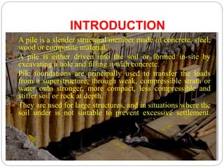
SlideShare a Scribd company logo
1 of 54
Prepared by:-
AKASH V. MODI
Assistant Professor
Civil Engg. Dept.
Merchant Engineering College, Basna
PILE FOUNDATION
INTRODUCTION
 A pile is a slender structural member made of concrete, steel,
wood or composite material.
 A pile is either driven into the soil or formed in-site by
excavating a hole and filling it with concrete.
 Pile foundations are principally used to transfer the loads
from a superstructure, through weak, compressible strata or
water onto stronger, more compact, less compressible and
stiffer soil or rock at depth.
 They are used for large structures, and in situations where the
soil under is not suitable to prevent excessive settlement.
NECESSITY OF PILE
FOUNDATIONS
 The load of the super-structure is heavy and its distribution is
uneven.
 The top soil has poor bearing capacity.
 The subsoil water is high so that pumping of water from the open
trenches for the shallow foundation is difficult and
uneconomical.
 Large fluctuation in subsoil water level.
 The structure is situated on sea shore or river bed, where there is
danger of scouring action of water.
 Canal or deep drainage line exist near the foundation.
 The top soil is of expansive nature.
 For foundation of transmission towers and off-shore platforms
which are subjected to uplift forces.
CLASSIFICATION OF PILES
1. Based on Method of load transfer
2. Based on Materials and Composition
3. Based on Method of Installation
1. Based on Method of load transfer
1. END BEARING PILE
These piles are Penetrate through the soft soil and their Bottom or tips rest on hard
stratum. These piles act as columns.
For this pile Qu=Qp
where, Qu=ultimate load
Qp= Pile load
1. Based on Method of load transfer
2. FRICTION PILE
When Loose soil extend to a greater depth, Pile are driven at depth when friction
resistance developed equal to load coming on piles.
Qu = Qs
where, Qu=ultimate load
Qs = skin friction
1. Based on Method of load transfer
3. COMPACTION PILE
These piles are used to compact loose soils, increasing
their bearing capacity. Pile do not carry any load.
4. TENSION PILE
When structure subjected to uplift due to
hydrostatic pressure or over turning moment. It is
also called Uplift pile.
1. Based on Method of load transfer
5. ANCHOR PILE
These provided anchorage against the horizontal
pull from sheet pulling or any other pulling
forces.
6. FENDER PILE
These are used to protect water front structures
against impact from ships or other floating
objects.
7. BATTER PILE
They are used for resist large horizontal
forces or inclined forces.
8. SHEET PILE
They are used as bulk heads or as impervious
cutoff to reduce seepage and uplift under
hydraulic structures.
2.Based on Materials and Composition
1. STEEL PILE
 Steel piles may be of I-section or hollow pipe section 10 inches to 24
inches diameter with 3/8 inches thickness. These piles are later on filled
with concrete. Steel piles are mostly used as end bearing piles because
of their less available surface area to take the loads by frictional forces.
Advantages:
High axial working capacity. Wide variety of sizes. Easy onsite
modifications. Fairly easy to drive, minimal soil displacement, good
penetration through hard materials.
Disadvantages:
High cost, difficulty in delivery, relatively higher corrosion, noisy
driving.
2.Based on Materials and Composition
2. CONCRETE PILE
 Different types of concrete piles are used for different applications. Cast-in-
place concrete piles, or driven shafts are two great examples of how the can be
produced (made) and installed. When choosing a pile type, one should
generally consider the following conditions:
1- Poor quality of upper soil layers
2 - When we have expansive soil in construction site
3- To resist uplift forces
4- To resist lateral loads (horizontal)
5- Bridge abutment and piers
 Concrete piles can be either pre-cast pile, or cast in-situ. Concrete piles are
generally reinforced.
Advantage:
Relatively cheap It can be easily combined with concrete superstructure
Corrosion resistant It can bear hard driving
Disadvantage:
Difficult to transport Difficult to achieve desired cutoff.
2.Based on Materials and Composition
3. TIMBER PILES
 These are made from tree trunks. These piles are available in
length between 4 to 6 m. timber piles are used where good
bearing stratum is available at a relatively shallow depth.
4. COMPOSITE PILES
 A pile which is made up of two materials like concrete and
timber or concrete and steel is called composite pile.
5. SAND PILES
 Sand compaction piles consists of driving a hollow steel pipe
with the bottom closed with a collapsible plate down to the
required depth; filling it with sand, and withdrawing the pipe
while air pressure is directed against the sand inside it.
3. Based on Method of Installation
1. DRIVEN PILES:
Driven piles may be of concrete, steel or timber. These
piles are driven into the soil by the impact of hammer.
3. Based on Method of Installation
2. DRIVEN AND CAST-IN-SITU PILES:
It is a type of driven pile. They are constructed by
driving a steel casing in to the ground. The hole is
then filled with concrete by placing the
reinforcement and the casing is gradually fitted.
3. BORED PILES:
Bored piles are constructed in pre-bored holes either
using a casing or by circulating stabilizing agent like
betonies slurry.
4. SCREW PILES:
screw piles are screwed into the soil.
3. Based on Method of Installation
5. JACKED PILES:
These piles are jacked into the ground by applying a downward force by a
hydraulic jack.
FACTORS INFLUENCING
SELECTION OF PILES
1. Length of the pile in relation to the load and type of soil
2. Characters of structure
3. Availability of the materials
4. Types of loading
5. Factors causing deterioration,
6. Ease of maintenance
7. Estimated cost of types of piles, taking into account the initial
cost, life expectancy and cost of
maintenance
8. Availability of funds.
9. Comparative costs in place. Durability required.
10. Types of structures adjacent to the project. Depth and kind of
water
PILE ACCESSORIES
1. PILE CAP
 To protect the top of pile from blow of hammer on top, pile cap is
provided.
 Normally, Pile cap is made of steel. The Thickness and size of cap is
depend upon shape and size of pile driving hammer.
 These Pile should penetrate into the cap for at least 10 cm length.
 Incase of group of piles, a common R.C.C. is provided for all the piles.
PILE ACCESSORIES
2. PILE SHOE
 A pile shoe is fitted at bottom end of pile to protect
the pile and to facilitate easy pile driving.
 Pile shoe are made of cast iron, steel or wrought iron.
PILE DRIVING
 The operation of forcing or inserting a pile into ground
without any previous excavation is called Pile Driving.
 Pile are driven into the ground by means of hammer.
The equipment used for lifting hammer and allow to
fall on head of pile is known as Pile driver.
 Various method for pile driving are
1. Hammer driving
2. Vibratory pile driver
3. Water jetting and hammering
4. Partial angering method
PILE DRIVING
 Points to be considered for selection of pile driving
method:
1. Type of soil at site
2. Costs of pile driving equipment
3. Availability of fluid pressure
4. Material of pile
5. Length of pile
6. Ground water level
PILE DRIVING
HAMMER DRIVING
 Equipment required for hammer driving:
1) Pile frame or pile driving rig
2) Pile hammer
3) Leads
4) Winches
5) Miscellaneous equipment
PILE DRIVING
 Hammers adopted for driving the pile are of the
following types:
1. Drop hammer
2. Single acting hammer
3. Double acting hammer
4. Diesel hammer
5. Vibratory hammer.
PILE DRIVING
1. DROP HAMMER
 A drop hammer is raised by a winch and allowed to drop
the top of the pile under gravity from a certain height.
 During the driving operation a cap is fixed to the pile and
cushion is generally provided between the pile
and the cap.
 Another cushion known as hammer cushion is placed on
the pile cap on which the hammer causes the impact.
 The drop hammer is the oldest type of hammer used pile
driving. It is rarely used these days because of very slow
rate of hammer blows.
PILE DRIVING
2. SINGLE ACTING HAMMER
 The ram is raised by air or steam under pressure to the
required height. It is then allowed to fall under gravity on the
top of the pile cap.
 The weight of hammer is about 1000 kg to 10,000 kg.
 Blows delivered much more rapidly than drop hammer.
3. DOUBLE ACTING HAMMER
 A heavy hammer is dropped on to the pile through a small
height but in quick succession. It is also called steam hammer.
 The weight of the hammer may be about 1000 kg to 2500 kg.
 Special devices are used to protect the heads of the piles from
damage due to excessive blows, which they receive.
LOAD CARRYING CAPACITY OF
PILES
 Ultimate load bearing capacity of a pile is defined as
the maximum load which can be carried by a pile and
at which the pile continues to sink without further
increase of the load.
 The allowable load is the safe load which the pile can
carry safely, which can be determined from ultimate
load bearing capacity dividing by suitable F.O.S.
 The pile transfers the load to the soil in two ways:
1. The resistance offered by soil at end or tip of pile is termed as
END BEARING or POINT BEARING.
2. The shear resistance on the surface of pile is termed as SKIN
FRICTION. Piles in homogeneous soils transfer the greater
part of their load by skin friction called Friction Piles.
LOAD CARRYING CAPACITY OF
PILES
 Load carrying capacity of piles can be determined by
1. Static formulae
2. Dynamic formulae
3. Pile load tests
4. Penetration tests
LOAD CARRYING CAPACITY OF
PILES
1. STATIC FORMULAE
 The sum of end bearing resistance and skin friction
resistance.
Qu = Qp + Qs Qp = qp*Ap Qs = fs*As
Qu=Ultimate bearing load of pile
qp=unit end bearing resistance of pile
Ap=area at base or tip of pile
fs=unit skin friction
As=surface area of pile in contact with soil
LOAD CARRYING CAPACITY OF
PILES
2. DYNAMIC FORMULAE
 Various Dynamic formula
1) Engineering News Record (ENR) formula
2) Hiley’s formula
3) Danish formula
LOAD CARRYING CAPACITY OF
PILES
2. DYNAMIC FORMULAE
1) Engineering News Record (ENR) formula
 The allowable load is given by
Qa= Allowable load in kN
W = Weight of hammer in kN
h = Height of fall in mm
s = penetration per blow
c = Empirical constant (drop hammer= 25 mm, single
acting hammer=2.5 mm)
F = Factor of safety = 6
LOAD CARRYING CAPACITY OF
PILES
2. DYNAMIC FORMULAE
2) Hiley’s formula
Where, Qd= ultimate load on a pile
C= toatal elastic compression
C = C1+C2+C3, temporary elastic compression
of dolly
and packing, pile & soil respectively.
𝜼𝒉 = efficiency of hammer
𝜼𝒃=efficiency of hammer blow
NEGATIVE SKIN FRICTION
 When soil layer surrounding a portion of the pile shaft
settles more than the pile, a downward drag is exerted
on the pile which is known as Negative Skin Friction.
• Negative Skin Friction will occur due to the
following reasons:
1. When the surrounding compressible soil has been
recently filled.
2. If the fill material is loose cohesion less soil.
3. By lowering the ground water which increases the
effective stress causing consolidation of the soil
with resultant settlement and friction force being
developed on the pile.
4. When fill is over the peat or a soft clay stratum.
UNDER REAMED PILES
 These piles are developed by C.B.R.I for serving
foundation for black cotton soils, filled up ground and
other type of soil having poor bearing capacity.
UNDER REAMED PILES
 An under reamed pile is bored cast-in-situ concrete pile having
one or more bulbs or under reamed in its lower level.
 The bulb or under reamed are formed by under reaming tool.
 Diameter of pile is 20 to 50 cm and bulb diameter is 2-3 times of
diameter of pile.
 Length of pile is 3 to 8 m and spacing between piles are 2 to 4 m.
 Load carrying capacity can increase by making more bulb at the
base.
 The vertical spacing between two bulb is varies from 1.25 to 1.5
times diameter of bulb.
 For black cotton soil the bulb is increase bearing capacity and
also provide anchorage against uplift.
UNDER REAMED PILES
ADVANTAGES:
1. They do not require heavy excavation.
2. No shoring is required.
3. No back filling is required.
4. The quantity of materials required for these piles is
less.
5. They prove to be economical to the tune of about 15
to 20% over the conventional strip footing.
CONSTRUCTION OF UNDER
REAMED PILES OR FIELD
INSTALLATION
CONSTRUCTION OF UNDER
REAMED PILES OR FIELD
INSTALLATION
 The equipment required for the construction of pile are
1. Spiral auger - for boring
2. Under reamer - for making bulb
3. Boring guide -to keep the hole vertical
CONSTRUCTION PROCEDURE
1. The ground is levelled and boring guide is correctly
positioned. Soil inside the round collar is taken out.
2. The under reaming tool, attached with a bucket at its end is
then lowered in the hole with help of the boring guide.
3. The bulb so formed is inspected and measured with the help of
a guide tool. A reinforcement cage is then lowered in bore hole
so formed. A concrete tunnel is then placed on top of bore
hole.
4. Concrete is gradually poured in the hole and compacted.
PILE LOAD TEST
 This test is used to determine the LOAD CARRYING
CAPACITY of a pile.
 Pile load tests are very useful for cohesionless soils.
 Pile load tests were conducted on the side that had the very soft
clay layer. Pile load tests of single piles passed.
 This test gives us the value of
1. Ultimate Load Value
2. Safe Load Value
3. Settlement under Different Values of Loads
 Load tests on piles are conducted on completion of 28 days
after casting of piles.
 As per IS:2911(Part-4)-1985,Two types of tests namely initial
and routine tests, for each type of loading viz. vertical,
horizontal pull out, are performed on piles.
PILE LOAD TEST
PILE LOAD TEST
PROCEDURE:
 The set-up consists of two anchor piles provided with an
anchor girder or reaction girder at their top.
 The test pile is installed between the anchor piles as like
foundation pile is installed. The test pile should be at lest
3B or 2.5m clear from the anchor pile.
 The test is conducted after a rest period of 3 days after the
installation in sandy soils and period of one month in silts
and soft clays.
 The load is applied through a hydraulic jack resting on the
reaction girder or Truss. The measurement of pile
movement are taken with respect to a fixed reference mark.
 The load is applied in equal increment of about 20% of the
allowable load.
PILE LOAD TEST
PROCEDURE:
 Settlement should be recorded with 3 dial gauges. Each stage of
the loading is maintained till the rate of movement of the pile top
is not more than 0.1mm per hour in sandy soils and 0.02mm per
hour in case of clayey soils as maximum of two hours.
 Under each load increment, settlements are observed at 0.5, 1, 2,
4, 8, 12, 16, 20, 60 minutes.
 The loading should be continued up to twice the safe load or the
load at which the total settlement reaches a specified value.
 The load is removed in the same decrements at 1 hour interval &
the final rebound recorded 24 hours after the entire load has been
removed.
 Plot a graph of Load vs Settlement and make a curve for loading
as well as unloading obtained from a pile load test.
PILE LOAD TEST
Figure shows a typical Load-Settlement curve for loading as well as unloading
from a pile load test.
PILE LOAD TEST
 For any given load, the net pile settlement (Sn )
is given by,
Sn = St - Se
Where ,
St = Total settlement (gross settlement)
Se = Elastic settlement (rebound)
GROUP ACTION OF PILES
Structural loads are supported by several piles acting as a group. A minimum
number of three piles is used under a column in a triangular pattern, even if the load
does not warrant the use of three piles.
Piles under a wall are arranged on either side of centre line of wall in a staggered
formation.
GROUP ACTION OF PILES
PILE SPACING
 The center to center distance between two piles in a row is known pile spacing.
 Normally pile spacing is taken as 2 x diagonal dimension of pile in case of Square piles
and 2.5 x diameter of pile in case of circular or octagonal piles.
 It has to be carefully designed by considering the following factors
1. Types of piles
2. Material of piles
3. Length of piles
4. Grouping of piles
5. Load coming on piles
6. Obstruction during pile driving
7. Nature of soil in which pile is to be driven
GROUP ACTION OF PILES
LOAD CARRYING CAPACITY OF
PILE GROUP
 The ultimate load carrying capacity
of pile group is not necessarily equal
to the sum of the individual load
capacities of the piles in the group.
 The load carrying capacity of
equivalent large pile (block) is
obtained by determining skin
friction resistance around the
embedded perimeter of pile group
and calculating end bearing
resistance by assuming a tip area
formed by block.
 The load carrying capacity of a pile
group is taken as smaller of
following:
1. The sum of load carrying
capacities of individual piles.
2. Load carrying capacity of single
large equivalent pile (block).
GROUP ACTION OF PILES
LOAD CARRYING CAPACITY OF PILE GROUP
 The load carrying capacity of pile group
Qg = n * Qu
where, n = Number of piles in a group
 There are two modes of failure of a pile group:
1. Block failure (capacity)
Qg(u) = qp*Ag + C*(Pg*D)
where, Ag = bearing area of group
Pg = perimeter of group
D = Length of pile
Nc = 9
œ = adhesion factor
C = qu/2
2. Individual pile failure (capacity)
Qu = qp*Ap + œ*C*(P*D) = C*Nc*Ap + œ*C*(P*D)
EFFICIENCY OF PILE GROUP
 It is the ratio of load carrying capacity of pile group to
sum of load carrying capacities of individual piles.
 The efficiency of pile group depends on the following
factors:
1. Spacing of piles
2. Total number of piles in a row and number of rows in
a group
3. Characteristics of pile (material, diameter and length)
PLATE LOAD TEST
 Plate Load Test is a field test for determining the ultimate
bearing capacity of soil and the likely settlement under a given
load.
 Circular or square bearing plates of mild steel not less than
25mm in thickness and varying in size from 300 - 750mm.
 The subgrade modulus is defined as the load intensity ‘p’ applied
on the standard plate per unit deflection i.e. k=p/d, value of
d=1.25mm.
 The test load is gradually increased till the plate starts to sink at a
rapid rate. The ultimate bearing capacity of soil is divided by
suitable factor of safety (which varies from 2 to 3) to arrive at
the value of safe bearing capacity of soil.
PLATE LOAD TEST
TEST SET UP
PLATE LOAD TEST
TEST SET UP
1. BY GRAVITY LOADING
PLATE LOAD TEST
TEST SET UP
1. BY LOADING TRUSS METHOD
PLATE LOAD TEST
APPARATUS
1. Test plate of square size
2. Hydraulic jack & pump
3. Pressure gauge
4. Proving ring or load cell
5. 4 no of dial gauges & dial gauge stands
6. Magnetic bases for dial gauges & supporting channels
7. Loading platform equipment or Truss with anchor rods
8. Plumb bob
9. Sprit level
10. Tripod
11. Pulley block
PLATE LOAD TEST
PROCEDURE
 To conduct the plate load test a pit of size 5Bp x 5Bp where Bp=width
of plate, is excavated up to a depth of Df where Df=depth of proposed
foundation.
 Generally 0.3 m2 plate is used and sometimes 0.6 m2 plate are also
used. so Bp=0.3 or 0.6.
 A central hole of depth Dp is made at the bottom of the test pit where,
Dp=(Bp/5Bp)x Df
 The plate is placed in the central hole and load is applied on it by a
hydraulic jack system.
 A seating load of 7 kN/m2 is first applied and released after some time
.After that load is increased in increment of 20% of rate estimated load
or 1/10th of ultimate load.
PLATE LOAD TEST
PLATE LOAD TEST
USES
1. To find out the ultimate bearing capacity of the proposed
foundation.
2. To determine the settlement of a footing under a given load
intensity.
3. Design a shallow footing for any Allowable settlement.
LIMITATION
1. The Plate Load Test being of short duration , does not give the
ultimate settlements particularly in case of cohesive soils.
2. The width of the plate should not be less than 30cm.
3. The foundation settlements is loose sands are usually much
larger than what is predicted by plate load test.
4. The settlement influence zone is much larger for the real
foundation sizes than that for the test plate.

More Related Content

What's hot

What's hot (20)

Pile foundation
Pile foundationPile foundation
Pile foundation
 
Plate load test ppt
Plate load test pptPlate load test ppt
Plate load test ppt
 
Pile and pile driving equipments
Pile and pile driving equipmentsPile and pile driving equipments
Pile and pile driving equipments
 
Bearing capacity theory is code ,vesic ,hansen, meyerhof, skemptons( usefulse...
Bearing capacity theory is code ,vesic ,hansen, meyerhof, skemptons( usefulse...Bearing capacity theory is code ,vesic ,hansen, meyerhof, skemptons( usefulse...
Bearing capacity theory is code ,vesic ,hansen, meyerhof, skemptons( usefulse...
 
Under reamed piles
Under reamed pilesUnder reamed piles
Under reamed piles
 
Earth pressure
Earth pressureEarth pressure
Earth pressure
 
Special Concretes
Special Concretes Special Concretes
Special Concretes
 
Unit 2 Mechanical Modification
Unit 2 Mechanical ModificationUnit 2 Mechanical Modification
Unit 2 Mechanical Modification
 
Chapter 4.3 well foundation-final-ppt
Chapter 4.3   well foundation-final-pptChapter 4.3   well foundation-final-ppt
Chapter 4.3 well foundation-final-ppt
 
Pile foundation
Pile foundationPile foundation
Pile foundation
 
Soil stabilisation (1)
Soil stabilisation (1)Soil stabilisation (1)
Soil stabilisation (1)
 
Quick sand condation
Quick sand condationQuick sand condation
Quick sand condation
 
Sheet pile presentation
Sheet pile presentationSheet pile presentation
Sheet pile presentation
 
Lecture 2 bearing capacity
Lecture 2 bearing capacityLecture 2 bearing capacity
Lecture 2 bearing capacity
 
Flexible pavement presentation
Flexible pavement presentationFlexible pavement presentation
Flexible pavement presentation
 
Pile foundations
Pile foundationsPile foundations
Pile foundations
 
Dynamic compaction
Dynamic compactionDynamic compaction
Dynamic compaction
 
1.PILE FOUNDATION (ACE) 2160601 GTU
1.PILE FOUNDATION (ACE) 2160601 GTU1.PILE FOUNDATION (ACE) 2160601 GTU
1.PILE FOUNDATION (ACE) 2160601 GTU
 
Stone column
Stone columnStone column
Stone column
 
Ground improvement technique
Ground improvement techniqueGround improvement technique
Ground improvement technique
 

Similar to PILE FOUNDATION BY AKASH V. MODI

Pile foundation
Pile foundation Pile foundation
Pile foundation Chandan K B
 
Pile Foundation - Rohan Dasgupta.pdf
Pile Foundation - Rohan Dasgupta.pdfPile Foundation - Rohan Dasgupta.pdf
Pile Foundation - Rohan Dasgupta.pdfRohan Dasgupta
 
GT-II-Unit-III-PILE-PartA.pptx
GT-II-Unit-III-PILE-PartA.pptxGT-II-Unit-III-PILE-PartA.pptx
GT-II-Unit-III-PILE-PartA.pptxAPURWAYAWALE
 
CHAPTER 5 DEEP FOUNDATION (2)7788788.ppt
CHAPTER 5 DEEP FOUNDATION (2)7788788.pptCHAPTER 5 DEEP FOUNDATION (2)7788788.ppt
CHAPTER 5 DEEP FOUNDATION (2)7788788.pptbryankalindo888
 
Types of pile foundation
Types of pile foundationTypes of pile foundation
Types of pile foundationdhruvalsu
 
Pile Foundation by Pratik Solanki (tes.google.com/site/infodiplomacivil/)
Pile Foundation by Pratik Solanki (tes.google.com/site/infodiplomacivil/)Pile Foundation by Pratik Solanki (tes.google.com/site/infodiplomacivil/)
Pile Foundation by Pratik Solanki (tes.google.com/site/infodiplomacivil/)Pratik Solanki
 
Rock mechanics for engineering geology (part 2)
Rock mechanics for engineering geology (part 2)Rock mechanics for engineering geology (part 2)
Rock mechanics for engineering geology (part 2)Jyoti Khatiwada
 
Deep foundation.types and design
Deep foundation.types and designDeep foundation.types and design
Deep foundation.types and designSasha Durrani
 
TYPES OF PILE FOUNDATION & APPLICATIONS
TYPES OF PILE FOUNDATION & APPLICATIONSTYPES OF PILE FOUNDATION & APPLICATIONS
TYPES OF PILE FOUNDATION & APPLICATIONSMaharshi Dave
 
Pile foundation
Pile foundationPile foundation
Pile foundationaranjalisp
 

Similar to PILE FOUNDATION BY AKASH V. MODI (20)

Pile foundation
Pile foundationPile foundation
Pile foundation
 
Pile foundation
Pile foundation Pile foundation
Pile foundation
 
DEEP FOUNDATION
DEEP FOUNDATIONDEEP FOUNDATION
DEEP FOUNDATION
 
Pile foundation
Pile foundationPile foundation
Pile foundation
 
Pile foundation
Pile foundationPile foundation
Pile foundation
 
Chapter 15
Chapter 15Chapter 15
Chapter 15
 
Pilefoundation
PilefoundationPilefoundation
Pilefoundation
 
Pile Foundation - Rohan Dasgupta.pdf
Pile Foundation - Rohan Dasgupta.pdfPile Foundation - Rohan Dasgupta.pdf
Pile Foundation - Rohan Dasgupta.pdf
 
GT-II-Unit-III-PILE-PartA.pptx
GT-II-Unit-III-PILE-PartA.pptxGT-II-Unit-III-PILE-PartA.pptx
GT-II-Unit-III-PILE-PartA.pptx
 
CHAPTER 5 DEEP FOUNDATION (2)7788788.ppt
CHAPTER 5 DEEP FOUNDATION (2)7788788.pptCHAPTER 5 DEEP FOUNDATION (2)7788788.ppt
CHAPTER 5 DEEP FOUNDATION (2)7788788.ppt
 
Types of pile foundation
Types of pile foundationTypes of pile foundation
Types of pile foundation
 
Pile Foundation by Pratik Solanki (tes.google.com/site/infodiplomacivil/)
Pile Foundation by Pratik Solanki (tes.google.com/site/infodiplomacivil/)Pile Foundation by Pratik Solanki (tes.google.com/site/infodiplomacivil/)
Pile Foundation by Pratik Solanki (tes.google.com/site/infodiplomacivil/)
 
Rock mechanics for engineering geology (part 2)
Rock mechanics for engineering geology (part 2)Rock mechanics for engineering geology (part 2)
Rock mechanics for engineering geology (part 2)
 
Pile footing.pptx
Pile footing.pptxPile footing.pptx
Pile footing.pptx
 
Pile foundation
Pile foundationPile foundation
Pile foundation
 
Deep foundation.types and design
Deep foundation.types and designDeep foundation.types and design
Deep foundation.types and design
 
TYPES OF PILE FOUNDATION & APPLICATIONS
TYPES OF PILE FOUNDATION & APPLICATIONSTYPES OF PILE FOUNDATION & APPLICATIONS
TYPES OF PILE FOUNDATION & APPLICATIONS
 
Pile foundation
Pile foundationPile foundation
Pile foundation
 
Pile foundtion
Pile foundtionPile foundtion
Pile foundtion
 
LECT 6 UPDATE.pdf
LECT  6 UPDATE.pdfLECT  6 UPDATE.pdf
LECT 6 UPDATE.pdf
 

More from MERCHANT ENGINEERING COLLEGE, BASNA (6)

ROLE OF ENGINEER IN A DEVELOPING INDIA
ROLE OF ENGINEER IN A DEVELOPING INDIAROLE OF ENGINEER IN A DEVELOPING INDIA
ROLE OF ENGINEER IN A DEVELOPING INDIA
 
WATER TURBINE BY AKASH V. MODI
WATER TURBINE BY AKASH V. MODIWATER TURBINE BY AKASH V. MODI
WATER TURBINE BY AKASH V. MODI
 
OPEN CHANNEL FOLW BY AKASH V. MODI
OPEN CHANNEL FOLW BY AKASH V. MODIOPEN CHANNEL FOLW BY AKASH V. MODI
OPEN CHANNEL FOLW BY AKASH V. MODI
 
GEOSYNTHETICS for FOUNDATION ENGINEERING
GEOSYNTHETICS for FOUNDATION ENGINEERINGGEOSYNTHETICS for FOUNDATION ENGINEERING
GEOSYNTHETICS for FOUNDATION ENGINEERING
 
METHODS OF IRRIGATION BY AKASH V. MODI
METHODS OF IRRIGATION BY AKASH V. MODIMETHODS OF IRRIGATION BY AKASH V. MODI
METHODS OF IRRIGATION BY AKASH V. MODI
 
House drainage system
House drainage systemHouse drainage system
House drainage system
 

Recently uploaded

(ANJALI) Dange Chowk Call Girls Just Call 7001035870 [ Cash on Delivery ] Pun...
(ANJALI) Dange Chowk Call Girls Just Call 7001035870 [ Cash on Delivery ] Pun...(ANJALI) Dange Chowk Call Girls Just Call 7001035870 [ Cash on Delivery ] Pun...
(ANJALI) Dange Chowk Call Girls Just Call 7001035870 [ Cash on Delivery ] Pun...ranjana rawat
 
Analog to Digital and Digital to Analog Converter
Analog to Digital and Digital to Analog ConverterAnalog to Digital and Digital to Analog Converter
Analog to Digital and Digital to Analog ConverterAbhinavSharma374939
 
Microscopic Analysis of Ceramic Materials.pptx
Microscopic Analysis of Ceramic Materials.pptxMicroscopic Analysis of Ceramic Materials.pptx
Microscopic Analysis of Ceramic Materials.pptxpurnimasatapathy1234
 
HARMONY IN THE NATURE AND EXISTENCE - Unit-IV
HARMONY IN THE NATURE AND EXISTENCE - Unit-IVHARMONY IN THE NATURE AND EXISTENCE - Unit-IV
HARMONY IN THE NATURE AND EXISTENCE - Unit-IVRajaP95
 
Introduction and different types of Ethernet.pptx
Introduction and different types of Ethernet.pptxIntroduction and different types of Ethernet.pptx
Introduction and different types of Ethernet.pptxupamatechverse
 
APPLICATIONS-AC/DC DRIVES-OPERATING CHARACTERISTICS
APPLICATIONS-AC/DC DRIVES-OPERATING CHARACTERISTICSAPPLICATIONS-AC/DC DRIVES-OPERATING CHARACTERISTICS
APPLICATIONS-AC/DC DRIVES-OPERATING CHARACTERISTICSKurinjimalarL3
 
(PRIYA) Rajgurunagar Call Girls Just Call 7001035870 [ Cash on Delivery ] Pun...
(PRIYA) Rajgurunagar Call Girls Just Call 7001035870 [ Cash on Delivery ] Pun...(PRIYA) Rajgurunagar Call Girls Just Call 7001035870 [ Cash on Delivery ] Pun...
(PRIYA) Rajgurunagar Call Girls Just Call 7001035870 [ Cash on Delivery ] Pun...ranjana rawat
 
Model Call Girl in Narela Delhi reach out to us at 🔝8264348440🔝
Model Call Girl in Narela Delhi reach out to us at 🔝8264348440🔝Model Call Girl in Narela Delhi reach out to us at 🔝8264348440🔝
Model Call Girl in Narela Delhi reach out to us at 🔝8264348440🔝soniya singh
 
Porous Ceramics seminar and technical writing
Porous Ceramics seminar and technical writingPorous Ceramics seminar and technical writing
Porous Ceramics seminar and technical writingrakeshbaidya232001
 
the ladakh protest in leh ladakh 2024 sonam wangchuk.pptx
the ladakh protest in leh ladakh 2024 sonam wangchuk.pptxthe ladakh protest in leh ladakh 2024 sonam wangchuk.pptx
the ladakh protest in leh ladakh 2024 sonam wangchuk.pptxhumanexperienceaaa
 
Gfe Mayur Vihar Call Girls Service WhatsApp -> 9999965857 Available 24x7 ^ De...
Gfe Mayur Vihar Call Girls Service WhatsApp -> 9999965857 Available 24x7 ^ De...Gfe Mayur Vihar Call Girls Service WhatsApp -> 9999965857 Available 24x7 ^ De...
Gfe Mayur Vihar Call Girls Service WhatsApp -> 9999965857 Available 24x7 ^ De...srsj9000
 
Processing & Properties of Floor and Wall Tiles.pptx
Processing & Properties of Floor and Wall Tiles.pptxProcessing & Properties of Floor and Wall Tiles.pptx
Processing & Properties of Floor and Wall Tiles.pptxpranjaldaimarysona
 
Software Development Life Cycle By Team Orange (Dept. of Pharmacy)
Software Development Life Cycle By  Team Orange (Dept. of Pharmacy)Software Development Life Cycle By  Team Orange (Dept. of Pharmacy)
Software Development Life Cycle By Team Orange (Dept. of Pharmacy)Suman Mia
 
SPICE PARK APR2024 ( 6,793 SPICE Models )
SPICE PARK APR2024 ( 6,793 SPICE Models )SPICE PARK APR2024 ( 6,793 SPICE Models )
SPICE PARK APR2024 ( 6,793 SPICE Models )Tsuyoshi Horigome
 
VIP Call Girls Service Kondapur Hyderabad Call +91-8250192130
VIP Call Girls Service Kondapur Hyderabad Call +91-8250192130VIP Call Girls Service Kondapur Hyderabad Call +91-8250192130
VIP Call Girls Service Kondapur Hyderabad Call +91-8250192130Suhani Kapoor
 
Structural Analysis and Design of Foundations: A Comprehensive Handbook for S...
Structural Analysis and Design of Foundations: A Comprehensive Handbook for S...Structural Analysis and Design of Foundations: A Comprehensive Handbook for S...
Structural Analysis and Design of Foundations: A Comprehensive Handbook for S...Dr.Costas Sachpazis
 

Recently uploaded (20)

(ANJALI) Dange Chowk Call Girls Just Call 7001035870 [ Cash on Delivery ] Pun...
(ANJALI) Dange Chowk Call Girls Just Call 7001035870 [ Cash on Delivery ] Pun...(ANJALI) Dange Chowk Call Girls Just Call 7001035870 [ Cash on Delivery ] Pun...
(ANJALI) Dange Chowk Call Girls Just Call 7001035870 [ Cash on Delivery ] Pun...
 
Exploring_Network_Security_with_JA3_by_Rakesh Seal.pptx
Exploring_Network_Security_with_JA3_by_Rakesh Seal.pptxExploring_Network_Security_with_JA3_by_Rakesh Seal.pptx
Exploring_Network_Security_with_JA3_by_Rakesh Seal.pptx
 
Analog to Digital and Digital to Analog Converter
Analog to Digital and Digital to Analog ConverterAnalog to Digital and Digital to Analog Converter
Analog to Digital and Digital to Analog Converter
 
Microscopic Analysis of Ceramic Materials.pptx
Microscopic Analysis of Ceramic Materials.pptxMicroscopic Analysis of Ceramic Materials.pptx
Microscopic Analysis of Ceramic Materials.pptx
 
HARMONY IN THE NATURE AND EXISTENCE - Unit-IV
HARMONY IN THE NATURE AND EXISTENCE - Unit-IVHARMONY IN THE NATURE AND EXISTENCE - Unit-IV
HARMONY IN THE NATURE AND EXISTENCE - Unit-IV
 
Introduction and different types of Ethernet.pptx
Introduction and different types of Ethernet.pptxIntroduction and different types of Ethernet.pptx
Introduction and different types of Ethernet.pptx
 
APPLICATIONS-AC/DC DRIVES-OPERATING CHARACTERISTICS
APPLICATIONS-AC/DC DRIVES-OPERATING CHARACTERISTICSAPPLICATIONS-AC/DC DRIVES-OPERATING CHARACTERISTICS
APPLICATIONS-AC/DC DRIVES-OPERATING CHARACTERISTICS
 
(PRIYA) Rajgurunagar Call Girls Just Call 7001035870 [ Cash on Delivery ] Pun...
(PRIYA) Rajgurunagar Call Girls Just Call 7001035870 [ Cash on Delivery ] Pun...(PRIYA) Rajgurunagar Call Girls Just Call 7001035870 [ Cash on Delivery ] Pun...
(PRIYA) Rajgurunagar Call Girls Just Call 7001035870 [ Cash on Delivery ] Pun...
 
Model Call Girl in Narela Delhi reach out to us at 🔝8264348440🔝
Model Call Girl in Narela Delhi reach out to us at 🔝8264348440🔝Model Call Girl in Narela Delhi reach out to us at 🔝8264348440🔝
Model Call Girl in Narela Delhi reach out to us at 🔝8264348440🔝
 
DJARUM4D - SLOT GACOR ONLINE | SLOT DEMO ONLINE
DJARUM4D - SLOT GACOR ONLINE | SLOT DEMO ONLINEDJARUM4D - SLOT GACOR ONLINE | SLOT DEMO ONLINE
DJARUM4D - SLOT GACOR ONLINE | SLOT DEMO ONLINE
 
Porous Ceramics seminar and technical writing
Porous Ceramics seminar and technical writingPorous Ceramics seminar and technical writing
Porous Ceramics seminar and technical writing
 
the ladakh protest in leh ladakh 2024 sonam wangchuk.pptx
the ladakh protest in leh ladakh 2024 sonam wangchuk.pptxthe ladakh protest in leh ladakh 2024 sonam wangchuk.pptx
the ladakh protest in leh ladakh 2024 sonam wangchuk.pptx
 
Call Us -/9953056974- Call Girls In Vikaspuri-/- Delhi NCR
Call Us -/9953056974- Call Girls In Vikaspuri-/- Delhi NCRCall Us -/9953056974- Call Girls In Vikaspuri-/- Delhi NCR
Call Us -/9953056974- Call Girls In Vikaspuri-/- Delhi NCR
 
Gfe Mayur Vihar Call Girls Service WhatsApp -> 9999965857 Available 24x7 ^ De...
Gfe Mayur Vihar Call Girls Service WhatsApp -> 9999965857 Available 24x7 ^ De...Gfe Mayur Vihar Call Girls Service WhatsApp -> 9999965857 Available 24x7 ^ De...
Gfe Mayur Vihar Call Girls Service WhatsApp -> 9999965857 Available 24x7 ^ De...
 
Processing & Properties of Floor and Wall Tiles.pptx
Processing & Properties of Floor and Wall Tiles.pptxProcessing & Properties of Floor and Wall Tiles.pptx
Processing & Properties of Floor and Wall Tiles.pptx
 
Software Development Life Cycle By Team Orange (Dept. of Pharmacy)
Software Development Life Cycle By  Team Orange (Dept. of Pharmacy)Software Development Life Cycle By  Team Orange (Dept. of Pharmacy)
Software Development Life Cycle By Team Orange (Dept. of Pharmacy)
 
9953056974 Call Girls In South Ex, Escorts (Delhi) NCR.pdf
9953056974 Call Girls In South Ex, Escorts (Delhi) NCR.pdf9953056974 Call Girls In South Ex, Escorts (Delhi) NCR.pdf
9953056974 Call Girls In South Ex, Escorts (Delhi) NCR.pdf
 
SPICE PARK APR2024 ( 6,793 SPICE Models )
SPICE PARK APR2024 ( 6,793 SPICE Models )SPICE PARK APR2024 ( 6,793 SPICE Models )
SPICE PARK APR2024 ( 6,793 SPICE Models )
 
VIP Call Girls Service Kondapur Hyderabad Call +91-8250192130
VIP Call Girls Service Kondapur Hyderabad Call +91-8250192130VIP Call Girls Service Kondapur Hyderabad Call +91-8250192130
VIP Call Girls Service Kondapur Hyderabad Call +91-8250192130
 
Structural Analysis and Design of Foundations: A Comprehensive Handbook for S...
Structural Analysis and Design of Foundations: A Comprehensive Handbook for S...Structural Analysis and Design of Foundations: A Comprehensive Handbook for S...
Structural Analysis and Design of Foundations: A Comprehensive Handbook for S...
 

PILE FOUNDATION BY AKASH V. MODI

  • 1. Prepared by:- AKASH V. MODI Assistant Professor Civil Engg. Dept. Merchant Engineering College, Basna PILE FOUNDATION
  • 2. INTRODUCTION  A pile is a slender structural member made of concrete, steel, wood or composite material.  A pile is either driven into the soil or formed in-site by excavating a hole and filling it with concrete.  Pile foundations are principally used to transfer the loads from a superstructure, through weak, compressible strata or water onto stronger, more compact, less compressible and stiffer soil or rock at depth.  They are used for large structures, and in situations where the soil under is not suitable to prevent excessive settlement.
  • 3. NECESSITY OF PILE FOUNDATIONS  The load of the super-structure is heavy and its distribution is uneven.  The top soil has poor bearing capacity.  The subsoil water is high so that pumping of water from the open trenches for the shallow foundation is difficult and uneconomical.  Large fluctuation in subsoil water level.  The structure is situated on sea shore or river bed, where there is danger of scouring action of water.  Canal or deep drainage line exist near the foundation.  The top soil is of expansive nature.  For foundation of transmission towers and off-shore platforms which are subjected to uplift forces.
  • 4. CLASSIFICATION OF PILES 1. Based on Method of load transfer 2. Based on Materials and Composition 3. Based on Method of Installation
  • 5. 1. Based on Method of load transfer 1. END BEARING PILE These piles are Penetrate through the soft soil and their Bottom or tips rest on hard stratum. These piles act as columns. For this pile Qu=Qp where, Qu=ultimate load Qp= Pile load
  • 6. 1. Based on Method of load transfer 2. FRICTION PILE When Loose soil extend to a greater depth, Pile are driven at depth when friction resistance developed equal to load coming on piles. Qu = Qs where, Qu=ultimate load Qs = skin friction
  • 7. 1. Based on Method of load transfer 3. COMPACTION PILE These piles are used to compact loose soils, increasing their bearing capacity. Pile do not carry any load. 4. TENSION PILE When structure subjected to uplift due to hydrostatic pressure or over turning moment. It is also called Uplift pile.
  • 8. 1. Based on Method of load transfer 5. ANCHOR PILE These provided anchorage against the horizontal pull from sheet pulling or any other pulling forces. 6. FENDER PILE These are used to protect water front structures against impact from ships or other floating objects. 7. BATTER PILE They are used for resist large horizontal forces or inclined forces. 8. SHEET PILE They are used as bulk heads or as impervious cutoff to reduce seepage and uplift under hydraulic structures.
  • 9. 2.Based on Materials and Composition 1. STEEL PILE  Steel piles may be of I-section or hollow pipe section 10 inches to 24 inches diameter with 3/8 inches thickness. These piles are later on filled with concrete. Steel piles are mostly used as end bearing piles because of their less available surface area to take the loads by frictional forces. Advantages: High axial working capacity. Wide variety of sizes. Easy onsite modifications. Fairly easy to drive, minimal soil displacement, good penetration through hard materials. Disadvantages: High cost, difficulty in delivery, relatively higher corrosion, noisy driving.
  • 10. 2.Based on Materials and Composition 2. CONCRETE PILE  Different types of concrete piles are used for different applications. Cast-in- place concrete piles, or driven shafts are two great examples of how the can be produced (made) and installed. When choosing a pile type, one should generally consider the following conditions: 1- Poor quality of upper soil layers 2 - When we have expansive soil in construction site 3- To resist uplift forces 4- To resist lateral loads (horizontal) 5- Bridge abutment and piers  Concrete piles can be either pre-cast pile, or cast in-situ. Concrete piles are generally reinforced. Advantage: Relatively cheap It can be easily combined with concrete superstructure Corrosion resistant It can bear hard driving Disadvantage: Difficult to transport Difficult to achieve desired cutoff.
  • 11. 2.Based on Materials and Composition 3. TIMBER PILES  These are made from tree trunks. These piles are available in length between 4 to 6 m. timber piles are used where good bearing stratum is available at a relatively shallow depth. 4. COMPOSITE PILES  A pile which is made up of two materials like concrete and timber or concrete and steel is called composite pile. 5. SAND PILES  Sand compaction piles consists of driving a hollow steel pipe with the bottom closed with a collapsible plate down to the required depth; filling it with sand, and withdrawing the pipe while air pressure is directed against the sand inside it.
  • 12. 3. Based on Method of Installation 1. DRIVEN PILES: Driven piles may be of concrete, steel or timber. These piles are driven into the soil by the impact of hammer.
  • 13. 3. Based on Method of Installation 2. DRIVEN AND CAST-IN-SITU PILES: It is a type of driven pile. They are constructed by driving a steel casing in to the ground. The hole is then filled with concrete by placing the reinforcement and the casing is gradually fitted. 3. BORED PILES: Bored piles are constructed in pre-bored holes either using a casing or by circulating stabilizing agent like betonies slurry. 4. SCREW PILES: screw piles are screwed into the soil.
  • 14. 3. Based on Method of Installation 5. JACKED PILES: These piles are jacked into the ground by applying a downward force by a hydraulic jack.
  • 15. FACTORS INFLUENCING SELECTION OF PILES 1. Length of the pile in relation to the load and type of soil 2. Characters of structure 3. Availability of the materials 4. Types of loading 5. Factors causing deterioration, 6. Ease of maintenance 7. Estimated cost of types of piles, taking into account the initial cost, life expectancy and cost of maintenance 8. Availability of funds. 9. Comparative costs in place. Durability required. 10. Types of structures adjacent to the project. Depth and kind of water
  • 16. PILE ACCESSORIES 1. PILE CAP  To protect the top of pile from blow of hammer on top, pile cap is provided.  Normally, Pile cap is made of steel. The Thickness and size of cap is depend upon shape and size of pile driving hammer.  These Pile should penetrate into the cap for at least 10 cm length.  Incase of group of piles, a common R.C.C. is provided for all the piles.
  • 17. PILE ACCESSORIES 2. PILE SHOE  A pile shoe is fitted at bottom end of pile to protect the pile and to facilitate easy pile driving.  Pile shoe are made of cast iron, steel or wrought iron.
  • 18. PILE DRIVING  The operation of forcing or inserting a pile into ground without any previous excavation is called Pile Driving.  Pile are driven into the ground by means of hammer. The equipment used for lifting hammer and allow to fall on head of pile is known as Pile driver.  Various method for pile driving are 1. Hammer driving 2. Vibratory pile driver 3. Water jetting and hammering 4. Partial angering method
  • 19. PILE DRIVING  Points to be considered for selection of pile driving method: 1. Type of soil at site 2. Costs of pile driving equipment 3. Availability of fluid pressure 4. Material of pile 5. Length of pile 6. Ground water level
  • 20. PILE DRIVING HAMMER DRIVING  Equipment required for hammer driving: 1) Pile frame or pile driving rig 2) Pile hammer 3) Leads 4) Winches 5) Miscellaneous equipment
  • 21. PILE DRIVING  Hammers adopted for driving the pile are of the following types: 1. Drop hammer 2. Single acting hammer 3. Double acting hammer 4. Diesel hammer 5. Vibratory hammer.
  • 22. PILE DRIVING 1. DROP HAMMER  A drop hammer is raised by a winch and allowed to drop the top of the pile under gravity from a certain height.  During the driving operation a cap is fixed to the pile and cushion is generally provided between the pile and the cap.  Another cushion known as hammer cushion is placed on the pile cap on which the hammer causes the impact.  The drop hammer is the oldest type of hammer used pile driving. It is rarely used these days because of very slow rate of hammer blows.
  • 23. PILE DRIVING 2. SINGLE ACTING HAMMER  The ram is raised by air or steam under pressure to the required height. It is then allowed to fall under gravity on the top of the pile cap.  The weight of hammer is about 1000 kg to 10,000 kg.  Blows delivered much more rapidly than drop hammer. 3. DOUBLE ACTING HAMMER  A heavy hammer is dropped on to the pile through a small height but in quick succession. It is also called steam hammer.  The weight of the hammer may be about 1000 kg to 2500 kg.  Special devices are used to protect the heads of the piles from damage due to excessive blows, which they receive.
  • 24. LOAD CARRYING CAPACITY OF PILES  Ultimate load bearing capacity of a pile is defined as the maximum load which can be carried by a pile and at which the pile continues to sink without further increase of the load.  The allowable load is the safe load which the pile can carry safely, which can be determined from ultimate load bearing capacity dividing by suitable F.O.S.  The pile transfers the load to the soil in two ways: 1. The resistance offered by soil at end or tip of pile is termed as END BEARING or POINT BEARING. 2. The shear resistance on the surface of pile is termed as SKIN FRICTION. Piles in homogeneous soils transfer the greater part of their load by skin friction called Friction Piles.
  • 25. LOAD CARRYING CAPACITY OF PILES  Load carrying capacity of piles can be determined by 1. Static formulae 2. Dynamic formulae 3. Pile load tests 4. Penetration tests
  • 26. LOAD CARRYING CAPACITY OF PILES 1. STATIC FORMULAE  The sum of end bearing resistance and skin friction resistance. Qu = Qp + Qs Qp = qp*Ap Qs = fs*As Qu=Ultimate bearing load of pile qp=unit end bearing resistance of pile Ap=area at base or tip of pile fs=unit skin friction As=surface area of pile in contact with soil
  • 27. LOAD CARRYING CAPACITY OF PILES 2. DYNAMIC FORMULAE  Various Dynamic formula 1) Engineering News Record (ENR) formula 2) Hiley’s formula 3) Danish formula
  • 28. LOAD CARRYING CAPACITY OF PILES 2. DYNAMIC FORMULAE 1) Engineering News Record (ENR) formula  The allowable load is given by Qa= Allowable load in kN W = Weight of hammer in kN h = Height of fall in mm s = penetration per blow c = Empirical constant (drop hammer= 25 mm, single acting hammer=2.5 mm) F = Factor of safety = 6
  • 29. LOAD CARRYING CAPACITY OF PILES 2. DYNAMIC FORMULAE 2) Hiley’s formula Where, Qd= ultimate load on a pile C= toatal elastic compression C = C1+C2+C3, temporary elastic compression of dolly and packing, pile & soil respectively. 𝜼𝒉 = efficiency of hammer 𝜼𝒃=efficiency of hammer blow
  • 30. NEGATIVE SKIN FRICTION  When soil layer surrounding a portion of the pile shaft settles more than the pile, a downward drag is exerted on the pile which is known as Negative Skin Friction. • Negative Skin Friction will occur due to the following reasons: 1. When the surrounding compressible soil has been recently filled. 2. If the fill material is loose cohesion less soil. 3. By lowering the ground water which increases the effective stress causing consolidation of the soil with resultant settlement and friction force being developed on the pile. 4. When fill is over the peat or a soft clay stratum.
  • 31. UNDER REAMED PILES  These piles are developed by C.B.R.I for serving foundation for black cotton soils, filled up ground and other type of soil having poor bearing capacity.
  • 32. UNDER REAMED PILES  An under reamed pile is bored cast-in-situ concrete pile having one or more bulbs or under reamed in its lower level.  The bulb or under reamed are formed by under reaming tool.  Diameter of pile is 20 to 50 cm and bulb diameter is 2-3 times of diameter of pile.  Length of pile is 3 to 8 m and spacing between piles are 2 to 4 m.  Load carrying capacity can increase by making more bulb at the base.  The vertical spacing between two bulb is varies from 1.25 to 1.5 times diameter of bulb.  For black cotton soil the bulb is increase bearing capacity and also provide anchorage against uplift.
  • 33. UNDER REAMED PILES ADVANTAGES: 1. They do not require heavy excavation. 2. No shoring is required. 3. No back filling is required. 4. The quantity of materials required for these piles is less. 5. They prove to be economical to the tune of about 15 to 20% over the conventional strip footing.
  • 34. CONSTRUCTION OF UNDER REAMED PILES OR FIELD INSTALLATION
  • 35. CONSTRUCTION OF UNDER REAMED PILES OR FIELD INSTALLATION  The equipment required for the construction of pile are 1. Spiral auger - for boring 2. Under reamer - for making bulb 3. Boring guide -to keep the hole vertical CONSTRUCTION PROCEDURE 1. The ground is levelled and boring guide is correctly positioned. Soil inside the round collar is taken out. 2. The under reaming tool, attached with a bucket at its end is then lowered in the hole with help of the boring guide. 3. The bulb so formed is inspected and measured with the help of a guide tool. A reinforcement cage is then lowered in bore hole so formed. A concrete tunnel is then placed on top of bore hole. 4. Concrete is gradually poured in the hole and compacted.
  • 36. PILE LOAD TEST  This test is used to determine the LOAD CARRYING CAPACITY of a pile.  Pile load tests are very useful for cohesionless soils.  Pile load tests were conducted on the side that had the very soft clay layer. Pile load tests of single piles passed.  This test gives us the value of 1. Ultimate Load Value 2. Safe Load Value 3. Settlement under Different Values of Loads  Load tests on piles are conducted on completion of 28 days after casting of piles.  As per IS:2911(Part-4)-1985,Two types of tests namely initial and routine tests, for each type of loading viz. vertical, horizontal pull out, are performed on piles.
  • 38. PILE LOAD TEST PROCEDURE:  The set-up consists of two anchor piles provided with an anchor girder or reaction girder at their top.  The test pile is installed between the anchor piles as like foundation pile is installed. The test pile should be at lest 3B or 2.5m clear from the anchor pile.  The test is conducted after a rest period of 3 days after the installation in sandy soils and period of one month in silts and soft clays.  The load is applied through a hydraulic jack resting on the reaction girder or Truss. The measurement of pile movement are taken with respect to a fixed reference mark.  The load is applied in equal increment of about 20% of the allowable load.
  • 39. PILE LOAD TEST PROCEDURE:  Settlement should be recorded with 3 dial gauges. Each stage of the loading is maintained till the rate of movement of the pile top is not more than 0.1mm per hour in sandy soils and 0.02mm per hour in case of clayey soils as maximum of two hours.  Under each load increment, settlements are observed at 0.5, 1, 2, 4, 8, 12, 16, 20, 60 minutes.  The loading should be continued up to twice the safe load or the load at which the total settlement reaches a specified value.  The load is removed in the same decrements at 1 hour interval & the final rebound recorded 24 hours after the entire load has been removed.  Plot a graph of Load vs Settlement and make a curve for loading as well as unloading obtained from a pile load test.
  • 40. PILE LOAD TEST Figure shows a typical Load-Settlement curve for loading as well as unloading from a pile load test.
  • 41. PILE LOAD TEST  For any given load, the net pile settlement (Sn ) is given by, Sn = St - Se Where , St = Total settlement (gross settlement) Se = Elastic settlement (rebound)
  • 42. GROUP ACTION OF PILES Structural loads are supported by several piles acting as a group. A minimum number of three piles is used under a column in a triangular pattern, even if the load does not warrant the use of three piles. Piles under a wall are arranged on either side of centre line of wall in a staggered formation.
  • 43. GROUP ACTION OF PILES PILE SPACING  The center to center distance between two piles in a row is known pile spacing.  Normally pile spacing is taken as 2 x diagonal dimension of pile in case of Square piles and 2.5 x diameter of pile in case of circular or octagonal piles.  It has to be carefully designed by considering the following factors 1. Types of piles 2. Material of piles 3. Length of piles 4. Grouping of piles 5. Load coming on piles 6. Obstruction during pile driving 7. Nature of soil in which pile is to be driven
  • 44. GROUP ACTION OF PILES LOAD CARRYING CAPACITY OF PILE GROUP  The ultimate load carrying capacity of pile group is not necessarily equal to the sum of the individual load capacities of the piles in the group.  The load carrying capacity of equivalent large pile (block) is obtained by determining skin friction resistance around the embedded perimeter of pile group and calculating end bearing resistance by assuming a tip area formed by block.  The load carrying capacity of a pile group is taken as smaller of following: 1. The sum of load carrying capacities of individual piles. 2. Load carrying capacity of single large equivalent pile (block).
  • 45. GROUP ACTION OF PILES LOAD CARRYING CAPACITY OF PILE GROUP  The load carrying capacity of pile group Qg = n * Qu where, n = Number of piles in a group  There are two modes of failure of a pile group: 1. Block failure (capacity) Qg(u) = qp*Ag + C*(Pg*D) where, Ag = bearing area of group Pg = perimeter of group D = Length of pile Nc = 9 œ = adhesion factor C = qu/2 2. Individual pile failure (capacity) Qu = qp*Ap + œ*C*(P*D) = C*Nc*Ap + œ*C*(P*D)
  • 46. EFFICIENCY OF PILE GROUP  It is the ratio of load carrying capacity of pile group to sum of load carrying capacities of individual piles.  The efficiency of pile group depends on the following factors: 1. Spacing of piles 2. Total number of piles in a row and number of rows in a group 3. Characteristics of pile (material, diameter and length)
  • 47. PLATE LOAD TEST  Plate Load Test is a field test for determining the ultimate bearing capacity of soil and the likely settlement under a given load.  Circular or square bearing plates of mild steel not less than 25mm in thickness and varying in size from 300 - 750mm.  The subgrade modulus is defined as the load intensity ‘p’ applied on the standard plate per unit deflection i.e. k=p/d, value of d=1.25mm.  The test load is gradually increased till the plate starts to sink at a rapid rate. The ultimate bearing capacity of soil is divided by suitable factor of safety (which varies from 2 to 3) to arrive at the value of safe bearing capacity of soil.
  • 49. PLATE LOAD TEST TEST SET UP 1. BY GRAVITY LOADING
  • 50. PLATE LOAD TEST TEST SET UP 1. BY LOADING TRUSS METHOD
  • 51. PLATE LOAD TEST APPARATUS 1. Test plate of square size 2. Hydraulic jack & pump 3. Pressure gauge 4. Proving ring or load cell 5. 4 no of dial gauges & dial gauge stands 6. Magnetic bases for dial gauges & supporting channels 7. Loading platform equipment or Truss with anchor rods 8. Plumb bob 9. Sprit level 10. Tripod 11. Pulley block
  • 52. PLATE LOAD TEST PROCEDURE  To conduct the plate load test a pit of size 5Bp x 5Bp where Bp=width of plate, is excavated up to a depth of Df where Df=depth of proposed foundation.  Generally 0.3 m2 plate is used and sometimes 0.6 m2 plate are also used. so Bp=0.3 or 0.6.  A central hole of depth Dp is made at the bottom of the test pit where, Dp=(Bp/5Bp)x Df  The plate is placed in the central hole and load is applied on it by a hydraulic jack system.  A seating load of 7 kN/m2 is first applied and released after some time .After that load is increased in increment of 20% of rate estimated load or 1/10th of ultimate load.
  • 54. PLATE LOAD TEST USES 1. To find out the ultimate bearing capacity of the proposed foundation. 2. To determine the settlement of a footing under a given load intensity. 3. Design a shallow footing for any Allowable settlement. LIMITATION 1. The Plate Load Test being of short duration , does not give the ultimate settlements particularly in case of cohesive soils. 2. The width of the plate should not be less than 30cm. 3. The foundation settlements is loose sands are usually much larger than what is predicted by plate load test. 4. The settlement influence zone is much larger for the real foundation sizes than that for the test plate.