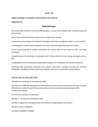
DATA LINK LAYER DEALS WITH THE lLLC LAYER AND MAC SUBLAYER.IT DEALS WITH FRAMING ,FLOW CONTROL,ERROR CONTROL.IT ALSO DEALS WITH RANDOM ACCESS METHODS AND PROTOCOLS
Data link control involves framing data, flow and error control, and common protocols like HDLC and PPP. Framing involves adding source/destination addresses to frames for transmission. Flow control restricts how much data the sender sends before waiting for acknowledgment. Error control uses techniques like automatic repeat request to retransmit lost data frames. HDLC and PPP are protocols that define frame formats and control procedures for point-to-point links.
Data link protocols provide control over data exchange at the data link layer through mechanisms like frame synchronization, flow control using stop-and-wait or sliding windows, and error control using automatic repeat request (ARQ) protocols like stop-and-wait, go-back-N, and selective-reject to handle lost or damaged frames. HDLC is a commonly used data link protocol that uses synchronous transmission of frames with flag fields, address fields, control fields, information fields, and frame check sequences along with three phases of operation and different frame types.
The document discusses data link control protocols that manage the exchange of data over a communication link. It covers several important topics:
1) Framing involves packing data bits into distinguishable frames using techniques like byte stuffing and bit stuffing.
2) Flow and error control ensure reliable data transmission by preventing buffer overflows and allowing retransmission of corrupted frames. Common methods are stop-and-wait and sliding window protocols.
3) Specific protocols like go-back-N and selective reject are examined, combining framing, flow control, and error handling over noiseless and noisy channels. Utilization rates under different protocols are also calculated.
The document discusses various functions and protocols of the data link layer, including framing, error control, flow control, and elementary protocols like stop-and-wait and sliding window protocols. It also covers topics like error detection codes, finite state machines, Petri nets, and example data link layer protocols including HDLC, PPP, and protocols used in the Internet.
The document summarizes key topics related to data link control and computer networks, including:
- Announcements about an upcoming midterm exam covering data link control topics.
- An overview of different types of flow control mechanisms used in the data link layer, including stop-and-wait and sliding window protocols.
- Details on error detection techniques like parity checking and cyclic redundancy checks (CRCs).
- Automatic repeat request (ARQ) error control mechanisms like stop-and-wait ARQ, go-back-N ARQ, and selective reject ARQ.
- An introduction to the High Level Data Link Control (HDLC) standard and its use of primary, secondary, and combined station types in different link configurations.
The document discusses data link control and framing in computer networks. It describes two main functions of the data link layer: defining frames and performing error detection on frames. It also discusses different types of framing such as fixed-size framing and variable-size framing using character-oriented and bit-oriented protocols. Specific protocols discussed include Stop-and-Wait ARQ which uses positive acknowledgments and retransmissions, and Go-Back-N ARQ which allows for pipelining of multiple frames before requiring an acknowledgment.
This document discusses data link layer protocols. It covers topics such as framing, flow control, error control, protocols for noisy and noiseless channels, and HDLC. Specific protocols discussed include stop-and-wait, go-back-N ARQ, and selective repeat ARQ. Examples are provided to illustrate how these protocols handle frame transmission and retransmission in different scenarios.
This document discusses various data link layer protocols for flow control. It describes an unrestricted simplex protocol with infinite buffer capacity and no need for flow control. For a simplex stop-and-wait protocol, a sequence number is needed to distinguish frames when the channel is noisy. A simplex protocol for a noisy channel uses positive acknowledgement and retransmission. This becomes a duplex channel, requiring a type field and ability to piggyback acknowledgements. A sliding window protocol maintains a sender and receiver window of allowed sequence numbers. It provides flexibility while ensuring ordered delivery to the network layer. Different sliding window protocols are examined, including ones using go-back-N and selective repeat.
Here is the presentation for Data Link Layer Numericals from the book Andrew S. Tanenbaum (Computer Networks) and B A Forouzan ( Data Communication and Networking)
The data link layer, or layer 2, is the second layer of the seven-layer OSI model of computer networking. This layer is the protocol layer that transfers data between adjacent network nodes in a wide area network (WAN) or between nodes on the same local area network (LAN) segment.
The data link layer provides services like error detection and correction to the network layer. It deals with issues like framing, flow control, and error handling when transmitting data frames between devices. Flow control mechanisms like stop-and-wait and sliding window are used to regulate frame transmission rates to prevent the receiver from being overwhelmed. Stop-and-wait allows sending one frame at a time while sliding window allows sending a fixed number of frames before needing an acknowledgment, improving efficiency over stop-and-wait. The data link layer frames network layer packets for transmission and handles issues like framing the data, detecting and correcting errors, and implementing flow control.
The document discusses data link layer protocols:
1. It describes the main functions of the data link layer including data link control, framing, error control, flow control, and media access control.
2. It introduces the Stop-and-Wait ARQ, Go-Back-N ARQ, and Selective Repeat ARQ protocols which combine framing, flow control, and error control to deliver data from one node to another over noisy channels.
3. It explains how these protocols use sequence numbers, sliding windows, and acknowledgments to provide flow and error control.
This document provides an overview of data link control (DLC) and data link layer protocols. It discusses the key functions of DLC including framing, flow control, and error control. Framing involves encapsulating data frames with header information like source and destination addresses. Flow control manages the flow of data between nodes while error control handles detecting and correcting errors. Common data link layer protocols described include simple protocol, stop-and-wait protocol, and High-Level Data Link Control (HDLC). HDLC is a bit-oriented protocol that supports full-duplex communication over both point-to-point and multipoint links. It uses three types of frames: unnumbered, information, and supervisory frames.
Presentation of computer network on data link layersumit gyawali
The document presents information on the data link layer and services provided by the link layer. It discusses how the data link layer transfers data between network layers on different machines, divides data into frames, and adds headers for physical addressing. It describes three main services provided - unacknowledged connectionless, acknowledged connection-oriented, and acknowledged connectionless. Finally, it outlines how the data link layer is implemented using network interface cards that handle framing, linking, flow control, and error detection.
The document provides information about the data link layer in the OSI model. It discusses that the data link layer is the second layer, and performs functions like addressing, flow control, error control, and accessing. It has two sublayers - logical link control and media access control. It provides services to the network layer like transferring data frames. The three main services are unacknowledged connectionless, acknowledged connectionless, and acknowledged connection-oriented. Error control methods like checksums are used. Flow control is implemented through protocols like stop-and-wait and sliding window. Framing converts data into frames. The medium access sublayer determines how nodes access shared channels and discusses protocols like ALOHA and CSMA.
This document summarizes key topics related to data link control and protocols. It discusses framing methods like fixed-size and variable-size framing. It also covers flow control, error control, and protocols for both noiseless and noisy channels. Specific protocols described include the Simplest Protocol, Stop-and-Wait Protocol, Stop-and-Wait ARQ, Go-Back-N ARQ, and Selective Repeat ARQ. The document provides details on their design, algorithms, and flow diagrams to illustrate how each protocol handles framing, flow control, and error control.
The Data Link Layer is responsible for framing data, providing addressing, error detection, flow control and media access control. It has two sublayers - the Logical Link Control for protocols, flow control and error control, and the Media Access Control for controlling the media. The Data Link Layer frames data from the Network Layer, provides hardware addressing, implements protocols like CSMA/CD for shared media access, and ensures reliable transmission through error detection using parity checks and CRC, as well as error correction and retransmission protocols.
Flow control and error control techniques in the data link layer protocolmdmuaj
This document provides information about flow control and error control techniques in data link layer protocols. It discusses three mechanisms: stop-and-wait, go-back-N ARQ, and selective-repeat ARQ. Stop-and-wait flow control involves a sender keeping a copy of the last frame until receiving an acknowledgement and resending any unacknowledged frames. Cyclic redundancy check (CRC) is described as an error detection code used to detect accidental changes to data by dividing the data and CRC by a generator polynomial. The document also includes an explanation of how CRC works at the sender and receiver.
Jaimin chp-3 - data-link layer- 2011 batchJaimin Jani
The document discusses data link layer services and functions including:
1. Providing interfaces between network layers and framing/error control/flow control.
2. Types of services include unacknowledged/acknowledged connectionless and connection-oriented.
3. Framing methods like character count, flag bytes, and encoding violations are used to delineate frames. Error control uses acknowledgments, timers, and sequence numbers.
HDLC is a bit-oriented synchronous data link layer protocol that provides both connectionless and connection-oriented services. It uses synchronous transmission in the form of frames with flag fields to delimit frames. There are three types of stations - primary controls the link, secondary operates under control of primary, and combined has features of both. Data can be transferred in normal response mode with an unbalanced configuration or asynchronous balanced mode with a balanced configuration. The frame structure includes address, control, information, and frame check sequence fields. HDLC operates in three phases - initialization, data exchange, and termination.
The document discusses the medium access control sub layer and various protocols used for channel allocation in computer networks, including ALOHA, carrier sense multiple access, collision-free protocols, and Ethernet. It describes how these protocols handle situations where multiple devices attempt to access shared network resources simultaneously to avoid collisions. Key aspects covered include how the protocols determine which device gets to use the channel, detect collisions, and retransmit frames when collisions occur to maximize throughput.
A sliding window protocol allows for reliable packet transmission over data links by assigning each packet a sequence number, tracking acknowledged packets, and allowing a limited number of unacknowledged packets to be transmitted at a time. It provides reliability through mechanisms like resending lost packets, while avoiding issues like unlimited sequence numbers by capping the number of unacknowledged transmittable packets with a window size. This sliding window approach balances reliability with throughput.
This document discusses different approaches for framing at the data link layer. It describes byte-oriented protocols like BISYNC, PPP that use sentinel characters or byte stuffing to delineate frames. The byte count approach used in DDCMP is also covered. For bit-oriented protocols, HDLC is described in detail, including its use of start/end bit sequences and bit stuffing to recognize frame boundaries despite corruption. Protocols like LCP, PAP, CHAP used along with PPP are also summarized briefly.
The document discusses flow control in TCP. It explains that TCP uses a sliding window mechanism for flow control to balance the sender's transmission rate with the receiver's reception rate. The sliding window allows packets within the window to be transmitted, and slides to the right when acknowledgments are received, making room for more packets. Problems like delayed acknowledgments, silly window syndrome, and solutions like Nagle's algorithm are also covered. TCP provides reliable data transfer using error control mechanisms like checksums, acknowledgments, and retransmissions of lost packets.
Error control techniques allow for detection and correction of errors during data transmission. Error control is implemented at the data link layer using automatic repeat request (ARQ) protocols like stop-and-wait and sliding window. Stop-and-wait involves transmitting a single frame and waiting for an acknowledgment before sending the next frame. Sliding window protocols allow multiple unacknowledged frames to be transmitted by using frame numbers and acknowledging receipt of frames. These protocols detect errors when frames are received out of sequence and trigger retransmission of lost frames.
The document provides information about various data link layer concepts including:
1. The data link layer provides framing, flow control, and error control between network layers on different machines. It uses devices like switches and bridges.
2. Error detection methods include parity checks, checksums, and CRC to detect errors in transmitted frames.
3. Data link protocols for flow control include stop-and-wait, sliding window protocols, and ARQ methods like go-back-N and selective repeat.
4. Framing encapsulates data with headers and trailers using fixed or variable size frames. Methods like byte stuffing and bit stuffing handle special characters in the data.
The document discusses various functions and protocols of the data link layer, including:
1. Framing of data, error detection using checksums, and flow control to prevent faster senders from overwhelming slower receivers.
2. Common data link layer protocols like stop-and-wait and sliding window protocols using go-back-N and selective repeat to allow multiple frames to be transmitted.
3. Error detection techniques like parity bits, checksums, and cyclic redundancy checks to detect errors in transmitted frames.
Different protocols for data communication networks Nt Arvind
Different protocols for data communication networks.
Variable-size framing protocols add header and trailer flags or bytes to distinguish frames. Character protocols use byte stuffing to avoid flag patterns in data. Bit protocols use bit stuffing to avoid flag bit patterns. Stop-and-wait protocols send one frame then wait for ACK before sending again. Go-back-N protocols send multiple frames before needing ACKs and resend missing frames. Selective repeat protocols resend only missing frames. HDLC is a common bit-oriented protocol that uses frame types and sequence/control fields. PPP is a byte-oriented protocol that carries user data or protocol information.
Flow control is used to prevent a sender from overwhelming a receiver. It uses feedback from the receiver to control sending. Stop-and-wait protocols only allow one frame to be sent before waiting for acknowledgement. Go-back-n protocols allow multiple unacknowledged frames but require resending all frames if any are lost. Selective repeat protocols only resend lost frames to improve efficiency.
The document discusses the data link layer of the OSI model. It has two main functions:
1. Ensuring error-free transmission of frames between two nodes on a network. This involves techniques like flow control, error control, framing, and physical addressing.
2. Controlling access to the transmission medium using methods like CSMA/CD for broadcast networks to avoid collisions between frames.
The data link layer is divided into logical link control and media access control sublayers. It receives packets from the network layer, divides them into frames, and sends the frames to the physical layer.
The document summarizes key aspects of the data link layer, including that it provides node-to-node communication, error control methods like CRC and checksum, access control methods like CSMA/CD, uses physical addresses, and sends data in frames. It then discusses flow control methods at the data link layer like stop-and-wait ARQ and sliding window protocols, providing details on how each method works, advantages, disadvantages, and examples.
The data link layer is the second layer in the OSI model. It receives data from the network layer, applies addressing information, and provides error control, flow control and access control. It has two sublayers - the logical link control and media access control. It offers three types of services to the network layer: unacknowledged connectionless, acknowledged connectionless, and acknowledged connection-oriented. Common functions of the data link layer include framing data, error control using checksums, and flow control using protocols like stop-and-wait and sliding window. The media access control sublayer determines how nodes access shared broadcast networks.
This document summarizes different data link layer flow control and error control protocols:
1) Stop-and-wait protocols require the sender to wait for an acknowledgment after sending each frame before sending the next frame. Automatic repeat request (ARQ) can be added to support retransmission of lost frames.
2) Sliding window protocols allow the sender to send multiple frames before waiting for an acknowledgment, improving throughput. Go-back-N ARQ requires retransmitting all unacknowledged frames if any frame is lost, while selective repeat ARQ only retransmits lost frames.
3) Flow control protocols like stop-and-wait and sliding windows control the flow of data to prevent the receiver from being overwhelmed
This document describes the sliding window protocol. It discusses key concepts like both the sender and receiver maintaining buffers to hold packets, acknowledgements being sent for every received packet, and the sender being able to send a window of packets before receiving an acknowledgement. It then explains the sender side process of numbering packets and maintaining a sending window. The receiver side maintains a window size of 1 and acknowledges by sending the next expected sequence number. A one bit sliding window protocol acts like stop and wait. Merits include multiple packets being sent without waiting for acknowledgements while demerits include potential bandwidth waste in some situations.
This document discusses various protocols used at the data link layer, including framing, flow control, and error control. It covers the simplest protocol, stop-and-wait protocol, and various automatic repeat request (ARQ) protocols for both noiseless and noisy channels. The key protocols discussed are stop-and-wait ARQ, go-back-N ARQ, and selective repeat ARQ. These protocols use concepts like framing, sequencing, acknowledgments, timers, and sliding windows to provide reliable data transmission over networks.
Data communication network ppt_Unit_4.pptxBHAVYPATEL34
This document provides an overview of the data link layer. It discusses the services provided by the network layer to the data link layer, including forwarding and routing. It describes framing, error control techniques like parity checks and checksums, and flow control methods like stop-and-wait and sliding window protocols. Specific data link layer protocols for internet connections like PPP are also mentioned.
U2CH1Data Link Layerxxxxxxxxxxxxxxxxx.pptxk2w9psdb96
1. The data link layer transforms the physical layer into a link responsible for node-to-node communication. It provides framing, addressing, error control, flow control, and media access control.
2. Error control uses acknowledgements, timers, and sequence numbers to ensure reliable delivery of frames. Framing groups bits into frames using techniques like bit stuffing. Flow control regulates data flow between sender and receiver.
3. Cyclic redundancy checks (CRCs) are commonly used for error detection. A CRC calculates a checksum by dividing the data by a fixed generator polynomial, allowing errors to be detected on receipt.
The document discusses the data link layer and its responsibilities. Specifically:
1) The data link layer transforms the physical layer into a link responsible for node-to-node communication. It is responsible for framing, addressing, flow control, error control, and media access control.
2) It provides services to the network layer like transferring data packets between network layers on different machines and offering various service models like unacknowledged connectionless, acknowledged connectionless, and acknowledged connection-oriented.
3) Key data link layer protocols are discussed including framing, error detection using CRC, flow control, and elementary protocol examples like unrestricted simplex and stop-and-wait.
The document provides an overview of the data link layer (DLL). It discusses how the DLL transforms the physical layer into a link responsible for node-to-node communication. The DLL is responsible for framing, addressing, flow control, error control, and media access control. It provides services like transferring data packets between network layers on different machines with options for unacknowledged connectionless, acknowledged connectionless, and acknowledged connection-oriented services. Key DLL functions include framing data into frames, error control using acknowledgements and retransmissions, and flow control to regulate data transmission rates.
This document discusses various data link layer protocols. It begins by describing the services provided by the data link layer, including framing, error control, and flow control. It then discusses different types of framing such as fixed-size and variable-size. The document also covers different protocols for handling flow control and error control, including stop-and-wait, go-back-N ARQ, and selective repeat ARQ. It analyzes the performance of these protocols on both noiseless and noisy channels.
The data link layer transforms the physical layer into a link responsible for node-to-node communication. It provides framing, addressing, error control, and flow control. Specific responsibilities include grouping bits into frames, adding addressing and error detection through checksums, and preventing fast senders from overwhelming slow receivers through flow control. Data link protocols must provide well-defined interfaces, handle transmission errors, and regulate data flow. They offer services like unacknowledged connectionless, acknowledged connectionless, and acknowledged connection-oriented to transfer data reliably between nodes.
The document provides an overview of the data link layer. It discusses how the data link layer transforms the physical layer into a link responsible for node-to-node communication. Specific responsibilities include framing, addressing, flow control, error control, and media access control. It then describes various data link layer services, design issues, error detection and correction techniques like parity checks, cyclic redundancy checks, and flow control mechanisms.
The document discusses various functions and protocols of the data link layer, including:
1. Framing of data, error detection using checksums, and flow control to prevent faster senders from overwhelming slower receivers.
2. Common data link layer protocols like stop-and-wait and sliding window protocols using go-back-N and selective repeat to allow multiple frames to be transmitted.
3. Error detection techniques like parity bits, checksums, and cyclic redundancy checks to detect errors in transmitted frames.
Elementary data link protocols are designed to perform framing, error control, and flow control. Framing divides bitstreams into frames of a few hundred to a few thousand bytes. The unrestricted simplex protocol allows one-way transmission with infinite buffers and no faults or lost frames. Stop-and-wait protocols provide one-way transmission and flow control for error-free channels, acknowledging each frame before sending the next. Noisy channel protocols use techniques like error detection and retransmission to minimize errors over noisy channels.
The document discusses various data link layer protocols for flow and error control. It begins by explaining the basic functions of flow control and error control. It then describes some simple protocols that could be used over noiseless channels, including the simplest protocol and stop-and-wait protocol. The document goes on to introduce protocols that add error control functionality to handle noisy channels, such as stop-and-wait automatic repeat request (ARQ). It provides examples of how these protocols work using sequencing and acknowledgments.
To transmit the data from one node to another, data link layer combines framing, flow control & error control schemes.
We divide the discussion protocols into those that can be used for noiseless(error free) channels and those that can be used for noisy (error creating) channels.
Embedded machine learning-based road conditions and driving behavior monitoringIJECEIAES
Car accident rates have increased in recent years, resulting in losses in human lives, properties, and other financial costs. An embedded machine learning-based system is developed to address this critical issue. The system can monitor road conditions, detect driving patterns, and identify aggressive driving behaviors. The system is based on neural networks trained on a comprehensive dataset of driving events, driving styles, and road conditions. The system effectively detects potential risks and helps mitigate the frequency and impact of accidents. The primary goal is to ensure the safety of drivers and vehicles. Collecting data involved gathering information on three key road events: normal street and normal drive, speed bumps, circular yellow speed bumps, and three aggressive driving actions: sudden start, sudden stop, and sudden entry. The gathered data is processed and analyzed using a machine learning system designed for limited power and memory devices. The developed system resulted in 91.9% accuracy, 93.6% precision, and 92% recall. The achieved inference time on an Arduino Nano 33 BLE Sense with a 32-bit CPU running at 64 MHz is 34 ms and requires 2.6 kB peak RAM and 139.9 kB program flash memory, making it suitable for resource-constrained embedded systems.
UNLOCKING HEALTHCARE 4.0: NAVIGATING CRITICAL SUCCESS FACTORS FOR EFFECTIVE I...amsjournal
The Fourth Industrial Revolution is transforming industries, including healthcare, by integrating digital,
physical, and biological technologies. This study examines the integration of 4.0 technologies into
healthcare, identifying success factors and challenges through interviews with 70 stakeholders from 33
countries. Healthcare is evolving significantly, with varied objectives across nations aiming to improve
population health. The study explores stakeholders' perceptions on critical success factors, identifying
challenges such as insufficiently trained personnel, organizational silos, and structural barriers to data
exchange. Facilitators for integration include cost reduction initiatives and interoperability policies.
Technologies like IoT, Big Data, AI, Machine Learning, and robotics enhance diagnostics, treatment
precision, and real-time monitoring, reducing errors and optimizing resource utilization. Automation
improves employee satisfaction and patient care, while Blockchain and telemedicine drive cost reductions.
Successful integration requires skilled professionals and supportive policies, promising efficient resource
use, lower error rates, and accelerated processes, leading to optimized global healthcare outcomes.
Use PyCharm for remote debugging of WSL on a Windo cf5c162d672e4e58b4dde5d797...shadow0702a
This document serves as a comprehensive step-by-step guide on how to effectively use PyCharm for remote debugging of the Windows Subsystem for Linux (WSL) on a local Windows machine. It meticulously outlines several critical steps in the process, starting with the crucial task of enabling permissions, followed by the installation and configuration of WSL.
The guide then proceeds to explain how to set up the SSH service within the WSL environment, an integral part of the process. Alongside this, it also provides detailed instructions on how to modify the inbound rules of the Windows firewall to facilitate the process, ensuring that there are no connectivity issues that could potentially hinder the debugging process.
The document further emphasizes on the importance of checking the connection between the Windows and WSL environments, providing instructions on how to ensure that the connection is optimal and ready for remote debugging.
It also offers an in-depth guide on how to configure the WSL interpreter and files within the PyCharm environment. This is essential for ensuring that the debugging process is set up correctly and that the program can be run effectively within the WSL terminal.
Additionally, the document provides guidance on how to set up breakpoints for debugging, a fundamental aspect of the debugging process which allows the developer to stop the execution of their code at certain points and inspect their program at those stages.
Finally, the document concludes by providing a link to a reference blog. This blog offers additional information and guidance on configuring the remote Python interpreter in PyCharm, providing the reader with a well-rounded understanding of the process.
Electric vehicle and photovoltaic advanced roles in enhancing the financial p...IJECEIAES
Climate change's impact on the planet forced the United Nations and governments to promote green energies and electric transportation. The deployments of photovoltaic (PV) and electric vehicle (EV) systems gained stronger momentum due to their numerous advantages over fossil fuel types. The advantages go beyond sustainability to reach financial support and stability. The work in this paper introduces the hybrid system between PV and EV to support industrial and commercial plants. This paper covers the theoretical framework of the proposed hybrid system including the required equation to complete the cost analysis when PV and EV are present. In addition, the proposed design diagram which sets the priorities and requirements of the system is presented. The proposed approach allows setup to advance their power stability, especially during power outages. The presented information supports researchers and plant owners to complete the necessary analysis while promoting the deployment of clean energy. The result of a case study that represents a dairy milk farmer supports the theoretical works and highlights its advanced benefits to existing plants. The short return on investment of the proposed approach supports the paper's novelty approach for the sustainable electrical system. In addition, the proposed system allows for an isolated power setup without the need for a transmission line which enhances the safety of the electrical network
Comparative analysis between traditional aquaponics and reconstructed aquapon...bijceesjournal
The aquaponic system of planting is a method that does not require soil usage. It is a method that only needs water, fish, lava rocks (a substitute for soil), and plants. Aquaponic systems are sustainable and environmentally friendly. Its use not only helps to plant in small spaces but also helps reduce artificial chemical use and minimizes excess water use, as aquaponics consumes 90% less water than soil-based gardening. The study applied a descriptive and experimental design to assess and compare conventional and reconstructed aquaponic methods for reproducing tomatoes. The researchers created an observation checklist to determine the significant factors of the study. The study aims to determine the significant difference between traditional aquaponics and reconstructed aquaponics systems propagating tomatoes in terms of height, weight, girth, and number of fruits. The reconstructed aquaponics system’s higher growth yield results in a much more nourished crop than the traditional aquaponics system. It is superior in its number of fruits, height, weight, and girth measurement. Moreover, the reconstructed aquaponics system is proven to eliminate all the hindrances present in the traditional aquaponics system, which are overcrowding of fish, algae growth, pest problems, contaminated water, and dead fish.
DEEP LEARNING FOR SMART GRID INTRUSION DETECTION: A HYBRID CNN-LSTM-BASED MODELgerogepatton
As digital technology becomes more deeply embedded in power systems, protecting the communication
networks of Smart Grids (SG) has emerged as a critical concern. Distributed Network Protocol 3 (DNP3)
represents a multi-tiered application layer protocol extensively utilized in Supervisory Control and Data
Acquisition (SCADA)-based smart grids to facilitate real-time data gathering and control functionalities.
Robust Intrusion Detection Systems (IDS) are necessary for early threat detection and mitigation because
of the interconnection of these networks, which makes them vulnerable to a variety of cyberattacks. To
solve this issue, this paper develops a hybrid Deep Learning (DL) model specifically designed for intrusion
detection in smart grids. The proposed approach is a combination of the Convolutional Neural Network
(CNN) and the Long-Short-Term Memory algorithms (LSTM). We employed a recent intrusion detection
dataset (DNP3), which focuses on unauthorized commands and Denial of Service (DoS) cyberattacks, to
train and test our model. The results of our experiments show that our CNN-LSTM method is much better
at finding smart grid intrusions than other deep learning algorithms used for classification. In addition,
our proposed approach improves accuracy, precision, recall, and F1 score, achieving a high detection
accuracy rate of 99.50%.
DEEP LEARNING FOR SMART GRID INTRUSION DETECTION: A HYBRID CNN-LSTM-BASED MODEL
PCCN DATA LINK LAYER UNIT 4 NOTES
1. Unit –IV
Subject :principles of computer communications and networks
Regulation:r16
Data link layer
The second layer of the DLL is the osi model provides a service to the network layer using the services of
physical layer.
Some of the services of the DL provides to the network layer includes.
1.provisioning links between the network entities(generally these are adjacent nodes in a sub network)
2.framing,which involves partitioning data into frames and exchanging these data into frames
3.frame sequencing which involves maintaining the correct order of the frames as they are being
exchanged.
4.Establishing and maintaining an acceptable level of flow control as frames being exchanged across a
link.
5.detecting the errors in the physical layer which includes error notification but not error correction.
6.Selecting QOS parameters associated with specific transmission including ensuring that sufficient
bandwidth is available and that transmission delays(i.e latency) are predictable and guaranteed
THE IEEE AND THE DATA LINK LAYER
No traditionsl standards are developed for LANS.
So in February 1980 IEEE developed the LAN standards for both physical and the data link layer using the
OSI reference model.ISO and IEC(international electro technical commission) are based on IEEE
networking standards.
A list of these standards are provided.
IEEE 802.1—Architectural overview of LANS.
IEEE 802.2-Logical link control(describes transmission of nodes between the frames.)
IEEE 802.3-Defines CSMA/CD
IEEE 802.3C-10MBPS ETHERNET
2. IEEE802.3U-100 MBPS ETHERNET
IEEE 802.3Z-GIGABIT ETHERNET
IEEE 802.4-TOKEN BUS NETWORK
IEEE802.5-LOGICAL RING LAN.
IEEE 802.6-Defines MANS.
IEEE 802.7-DEFINES THE BROAD BAND LANS.
IEEE 802.9-DEFINES INTEGRATED DIGITAL AND VIDEO NETWORKING-ISLANS
IEEE 802.10-STANDARDS FOR INTEROPERABLE.
IEEE 802.11-WLANS
IEEE 802.12-DEMAND PRIORITY ACCESS METHOD.
IEEE 802.14 CABLE TV BASED BROAD BAND COMMUNICATION.
Logical link control sublayer has 2 sub functions.
1.LLC has several functions including framing,flow control and error control.
2.MAC layer provides medium access control management protocols for accessing a shared medium.
Logical link control sublayer
1.framing
2.flow control
3.error control
3. Framing:
Framing refers to the process of partitioning the bit stram into discrete units or blocks of data called
frames.
Specific formats and timing sequences exist for each LAN type.
By partioning the bit stream into frames framing enables sending and receiving machines to synchronize
the transmission and reception of data.
Framing also facilitates error detection and correction.
Once a bit stream is portioned into frames specific information about the contents of the frame is
computed and transmitted within a frame.
Using this information a receiving node can determine the integrity of the received frame.
One common framing procedure involves inserting flag characters before and after the transmission of
the data message
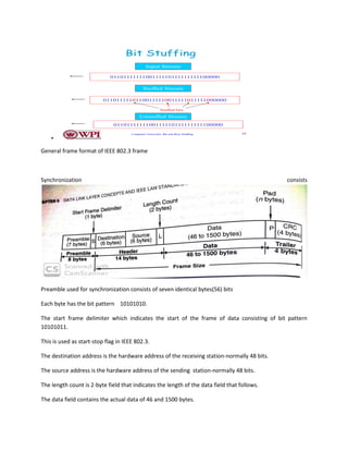
We will use the bit pattern 01111110 as our start-stop flags.
To distinguish the uniqueness of the start-stop flag bit pattern.
One way is bit stuffing
• Each frame begins and ends with a special bit pattern called a flag byte [01111110].
• Whenever sender data link layer encounters five consecutive ones in the data stream, it
automatically stuffs a 0 bit into the outgoing stream.
• When the receiver sees five consecutive incoming ones followed by a 0 bit, it automatically
destuffs the 0 bit before sending the data to the network layer.
4. •
Computer Networks: Bit and Byte Stuffing 15
Input Stream
Stuffed Stream
Unstuffed Stream
0110111111100111110111111111100000
01101111101100111110011111011111000000
0110111111100111110111111111100000
Stuffed bits
Bit Stuffing
General frame format of IEEE 802.3 frame
Synchronization consists
Preamble used for synchronization consists of seven identical bytes(56) bits
Each byte has the bit pattern 10101010.
The start frame delimiter which indicates the start of the frame of data consisting of bit pattern
10101011.
This is used as start-stop flag in IEEE 802.3.
The destination address is the hardware address of the receiving station-normally 48 bits.
The source address is the hardware address of the sending station-normally 48 bits.
The length count is 2-byte field that indicates the length of the data field that follows.
The data field contains the actual data of 46 and 1500 bytes.
5. The pad field contains the dummy data that pad the data field uptoits minimum length of 46 bytes.
CRC contains the information needed for error detection.
It is also called as FCs(frame check sequence)
Flow control
Flow control is the another function of the LLC sublayer refers to the process that controls the rate at
which data are exchanged between two nodes.
It involves a feed back mechanism that informs the source machine of the destination machines ability
to keep up with the current flow of the data transmission
A source node may not transmit until it gets permission from the destination machine.
Flow control is necessary because it is possible at a rate faster than the destination can receive and
process them.
This can happen when a source node is lightly loaded and the destination node is heavily loaded or if the
source node has a faster processor than that of the destination node.
If the server processing speed is much greater than the client then the server is able to transmit more
frames than the client can process them.
Stop and wait flow control protocol
▪ Sender keeps a copy of the last frame until it receives an acknowledgement.
▪ For identification, both data frames and acknowledgements (ACK) frames are numbered
alternatively 0 and 1.
▪ Sender has a control variable (S) that holds the number of the recently sent frame. (0 or 1)
▪ Receiver has a control variable ® that holds the number of the next frame expected (0 or 1).
▪ Sender starts a timer when it sends a frame. If an ACK is not received within a allocated time
period, the sender assumes that the frame was lost or damaged and resends it
▪ Receiver send only positive ACK if the frame is intact.
▪ ACK number always defines the number of the next expected frame
6. Sliding window flow control protocol
In sliding window method, multiple frames are sent by sender at a time before needing an
acknowledgment.
• Multiple frames sent by source are acknowledged by receiver using a single ACK frame.
Sliding Window
• Sliding window refers to an imaginary boxes that hold the frames on both sender and receiver side.
• It provides the upper limit on the number of frames that can be transmitted before requiring an
acknowledgment.
• Frames may be acknowledged by receiver at any point even when window is not full on receiver side.
• Frames may be transmitted by source even when window is not yet full on sender side.
• The windows have a specific size in which the frames are numbered modulo- n, which means they are
numbered from 0 to n-l. For e.g. if n = 8, the frames are numbered 0, 1,2,3,4,5,6, 7, 0, 1,2,3,4,5,6, 7, 0, 1,
The size of window is n-1. For e.g. In this case it is 7. Therefore, a maximum of n-l frames may
be sent before an acknowledgment.
• When the receiver sends an ACK, it includes the number of next frame it expects to receive.
For example in order to acknowledge the group of frames ending in frame 4, the receiver sends
an ACK containing the number 5. When sender sees an ACK with number 5, it comes to know
that all the frames up to number 4 have been received.
7. Sliding Window on Sender Side
• At the beginning of a transmission, the sender's window contains n-l frames.
• As the frames are sent by source, the left boundary of the window moves inward, shrinking the
size of window. This means if window size is w, if four frames are sent by source after the last
acknowledgment, then the number of frames left in window is w-4.
• When the receiver sends an ACK, the source's window expand i.e. (right boundary moves
outward) to allow in a number of new frames equal to the number of frames acknowledged by
that ACK.
• For example, Let the window size is 7 (see diagram (a)), if frames 0 through 3 have been sent
and no acknowledgment has been received, then the sender's window contains three frames -
4,5,6.
• Now, if an ACK numbered 3 is received by source, it means three frames (0, 1, 2) have been
received by receiver and are undamaged.
• The sender's window will now expand to include the next three frames in its buffer. At this
point the sender's window will contain six frames (4, 5, 6, 7, 0, 1). (See diagram (b)).
Sliding Window on Receiver Side
8. • At the beginning of transmission, the receiver's window contains n-1 spaces for frame but not the
frames.
• As the new frames come in, the size of window shrinks.
• Therefore the receiver window represents not the number of frames received but the number of
frames that may still be received without an acknowledgment ACK must be sent.
• Given a window of size w, if three frames are received without an ACK being returned, the number of
spaces in a window is w-3.
• As soon as acknowledgment is sent, window expands to include the number of frames equal to the
number of frames acknowledged.
• For example, let the size of receiver's window is 7 as shown in diagram. It means window contains
spaces for 7 frames.
• With the arrival of the first frame, the receiving window shrinks, moving the boundary from space 0 to
1. Now, window has shrunk by one, so the receiver may accept six more frame before it is required to
send an ACK.
• If frames 0 through 3 have arrived but have DOC been acknowledged, the window will contain three
frame spaces.
As receiver sends an ACK, the window of the receiver expands to include as many new placeholders as
newly acknowledged frames.
• The window expands to include a number of new frame spaces equal to the number of the most
recently acknowledged frame minus the number of previously acknowledged frame. For e.g., If window
size is 7 and if prior ACK was for frame 2 & the current ACK is for frame 5 the window expands by three
(5-2).
Therefore, the sliding window of sender shrinks from left when frames of data are sending. The sliding
window of the sender expands to right when acknowledgments are received.
9. • The sliding window of the receiver shrinks from left when frames of data are received. The sliding
window of the receiver expands to the right when acknowledgement is sent.
10.
11.
12. Error control
Error control refers to the process of guaranteeing reliable data delivery.
That is data received are identical to the data transmitted.
Two basic strategies exist for dealing with the errors.
The first one is error correction through retransmission involves just enough information in the data
stream so the receiving node can detect an error occurred during transmission.Once an error is detected
the receiving node can then request the sender to retransmit the unit of data.
13. The second method is autonomous error correction involves providing redudndant information in the
data stream so the destination node can detect and correct any erros automatically.
Both methods are the forms of error correction.
Error control using retransmission involves use of acks.
If the positive acks are received means frame received correctly.
If the negative acks are received means the frame is not received correctly.to guard the possibility of
lodt or destroyed frames,the DLL always supports timers.
If a frame or ack is lost the sending node limit eventually expires alerting it to retransmit the frame.using
the sequence nos we can identify the whether the frame is already received or not.
The concepts of error detection,ack and retransmission are collectively referred to as ARQ(automatic
repeat request)
1.stop and wait ARQ
• When a receiver receives a damaged frame, it discards it and keeps its value of R.
• After the timer at the sender expires, another copy of frame 1 is sent.
• Simplest flow and error control protocol
• Data frames and ACK frames are numbered alternately (0,1)
• When receiver sends ACK1: it acknowledges data frame 0 and is expecting data frame 1, ACK0
acknowledges data frame 1 and is expecting data frame 0
• Sequence Numbers are incremented modulo 2. 1+1 = 0 , and 0+1=1
• Receiver has a counter (R ) which hold the number of the expected frame to be received. R is
incremented by 1 modulo 2 when the expected frame is received.
• The sender keeps a counter (S ) which holds the number of the last transmitted frame. S is
incremented by 1 modulo 2 when the acknowledgement of the last transmitted frame is
received and the next frame is transmitted
14. ◼ If the receiver detects an error in the frame it discards it
◼ If the receiver receives an out-of-order frame ( frame 0 instead of frame 1 or vice versa), it
knows that the expected frame is lost or damaged and discards the out-of-order frame and
resend the previous ACK
◼ If the sender receives an ACK with a different number than the current value of S+1, it discards
it
◼ The sending device keeps a copy of the last frame transmitted until it receives the right
acknowledgment (ACK) for the frame
◼ The sender starts a timer when it sends a frame. If an ACK is not received within the allocated
time, the sender assumes that the frame was lost or damaged and resends it
15. piggybacking
Go-Back-N ARQ
Go-Back-N ARQ is a specific instance of automatic repeat request(ARQ) protocol which is an error
recovery mechanism to provide reliability. objects with a span smaller than the structuring element.
It is a special type of sliding window protocol.
In this the sending process continues to send a number of frames specified by a window size even
without receiving an acknowledgement (ACK) packet from the receiver. removes perimeter pixels from
larger image objects.
In Go-Back-N ARQ, the size of the sender window must be less than N and the size of the receiver
window is always 1.
When the frame is damaged the sender goes back and sends a set of frames starting from the last one
AKn‘d.
The number of retransmitted frames is N.
16. Selective repeat ARQ
Only damaged and lost frames are retransmitted
ACK numbers refer to the last correctly received frame, not next frame expected!
If go-back-n window size is n-1, SR widow size must be at most n/2 (why?)
Damaged Frames:
After receiving a damaged frame, receiver sends a NAK and continues accepting other frames
Sender only retransmits the missing frame
15 -Winter 2006
ECE
ECE 766
Computer Interfacing and Protocols
21
Selective Repeat ARQ
Host A Host B
Data 0
NAK 3
Data 1
Data 2
Data 3
Data 4
Data 5
Error, discard
Data 3
Window size 7
Error in data frame 3
Data 6
17. Types of errors
Single bit errors:
In a single-bit error, only 1 bit in the data unit has changed.
Burst errors
A burst error means that 2 or more bits in the data unit have changed.
To detect or correct errors, we need to send extra (redundant) bits with data.
Cyclic Redundancy Check
18. CRC
Given a k-bit frame or message, the transmitter generates an n-bit sequence, known as a frame check
sequence (FCS), so that the resulting frame, consisting of (k+n) bits, is exactly divisible by some
predetermined number.
The receiver then divides the incoming frame by the same number and, if there is no remainder,
assumes that there was no error.
19.
20. Medium access control sublayer
CSMA : Carrier Sense Multiple Access Protocols
1 – persistent CSMA
when a station is ready to send a frame , it senses the channel :
if busy : continuously sense it and waits for it to become free
if idle : sends it (with probability 1) ..hence the name 1 -persistent
if collision : waits for random time and tries again.
Nonpersistent CSMA.
Less greedy than 1 persistent , hence better channel utilization but longer delays
when a station is ready to send a frame , it senses the channel :
if busy : waits for random time rather than continuously sense it for the purpose of seizing it
if idle : sends it .
if collision : waits for random time and tries again
21. Carrier-sense multiple access with collision detection (CSMA/CD):
It is a media access control method used most notably in early Ethernet technology for local area
networking. It uses carrier-sensing to defer transmissions until no other stations are transmitting. This is
used in combination with collision detection in which a transmitting station detects collisions by sensing
transmissions from other stations while it is transmitting a frame. When this collision condition is
detected, the station stops transmitting that frame, transmits a jam signal, and then waits for a random
time interval before trying to resend the frame.
CSMA/CD is a modification of pure carrier-sense multiple access (CSMA). CSMA/CD is used to improve
CSMA performance by terminating transmission as soon as a collision is detected, thus shortening the
time required before a retry can be attempted.
22. CSMA/CA
CSMA/CA protocol is used in wireless networks because they cannot detect the collision so the only
solution is collision avoidance.
• CSMA/CA avoids the collisions using three basic techniques.
i) Interframe space
(ii) Contention window
(iii) Acknowledgements
1.Interframe Space (IFS)
• Whenever the channel is found idle, the station does not transmit immediately. It
waits for a period of time called interframe space (IFS).
• When channel is sensed to be idle, it may be possible that same distant station may
have already started transmitting and the signal of that distant station has not yet
reached other stations.
• Therefore the purpose of IFS time is to allow this transmitted signal to reach other
stations.
• If after this IFS time, the channel is still idle, the station can send, but it still needs to
wait a time equal to contention time.
• IFS variable can also be used to define the priority of a station or a frame.
2. Contention Window
• Contention window is an amount of time divided into slots.
• A station that is ready to send chooses a random number of slots as its wait time.
• The number of slots in the window changes according to the binary exponential back-
off strategy. It means that it is set of one slot the first time and then doubles each time
the station cannot detect an idle channel after the IFS time.
23. • This is very similar to the p-persistent method except that a random outcome defines
the number of slots taken by the waiting station.
• In contention window the station needs to sense the channel after each time slot.
• If the station finds the channel busy, it does not restart the process. It just stops the
timer & restarts it when the channel is sensed as idle.
3. Acknowledgement
• Despite all the precautions, collisions may occur and destroy the data.
• The positive acknowledgment and the time-out timer can help guarantee that receiver
has received the frame.
CSMA/CA Procedure:
Fig. Shows the flow chart explaining the principle of CSMA/CA.
This is the CSMA protocol with collision avoidance.
24. • The station ready to transmit, senses the line by using one of the persistent strategies.
• As soon as it find the line to be idle, the station waits for an IFG (Interframe gap)
amount of time.
• If then waits for some random time and sends the frame.
• After sending the frame, it sets a timer and waits for the acknowledgement from the
receiver.
• If the acknowledgement is received before expiry of the timer, then the transmission is
successful.
• But if the transmitting station does not receive the expected acknowledgement before
the timer expiry then it increments the back off parameter, waits for the back off time
and resenses the line.
TOKEN PASSING PROTOCOL
The permission is provided in the form of a special control frame called a token.
The node that possess the token may access the medium.
The principle of token passing protocol is simple.The node that possess the token may access the
medium.since the possession of token control access to the medium the possibility of contention is
eliminated.the absence of contention is the absence of collisions.
In token passing scheme, the stations are connected logically to each other in form of ring and access of
stations is governed by tokens.
A token is a special bit pattern or a small message, which circulate from one station to the next in the
some predefined order.
In Token ring, token is passed from one station to another adjacent station in the ring whereas incase of
Token bus, each station
uses the bus to send the token to the next station in some predefined order.
In both cases, token represents permission to send. If a station has a frame queued for transmission
when it receives the token, it can send that frame before it passes the token to the next station. If it has
no queued frame, it passes the token simply.
After sending a frame, each station must wait for all N stations (including itself) to send the token to
their neighbors and the other N – 1 stations to send a frame, if they have one.
There exists problems like duplication of token or token is lost or insertion of new station, removal of a
station, which need be tackled for correct and reliable operation of this scheme.