The document outlines pavement design principles, detailing the characteristics and construction of flexible, rigid, and composite pavements. It discusses the importance of subgrade properties and evaluation methods, the factors influencing pavement design, and traffic considerations for ensuring structural integrity. Additionally, it presents the AASHTO design methodology and traffic growth assessments for various road types and load factors.


![Computation of Traffic for Use of Pavement
Thickness Design Chart
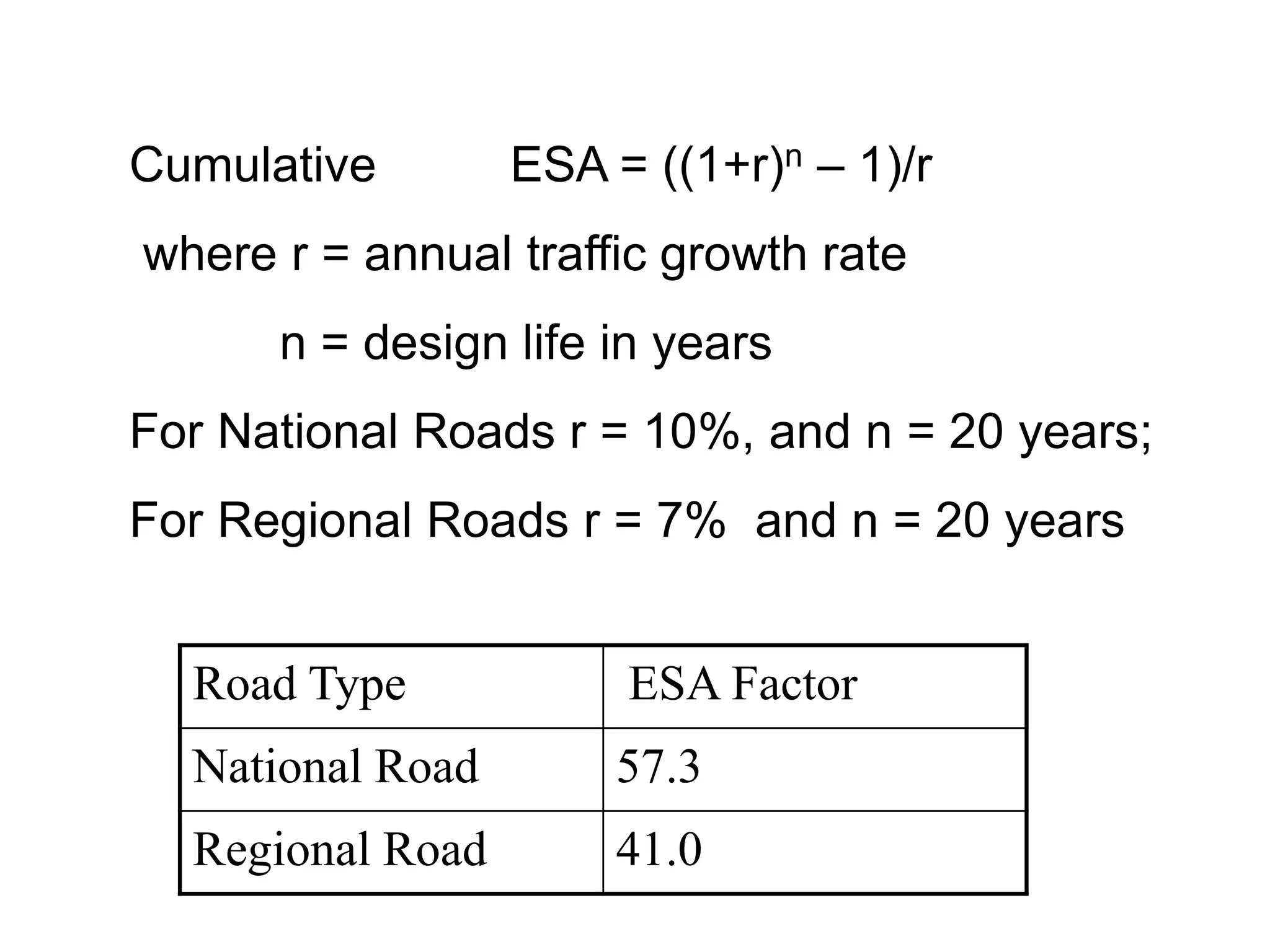
365 xA[(1+r)n – 1]
N = --------------------------- x D x F
r
N = Cumulative No. of standard axles to be catered for the
design in terms of msa
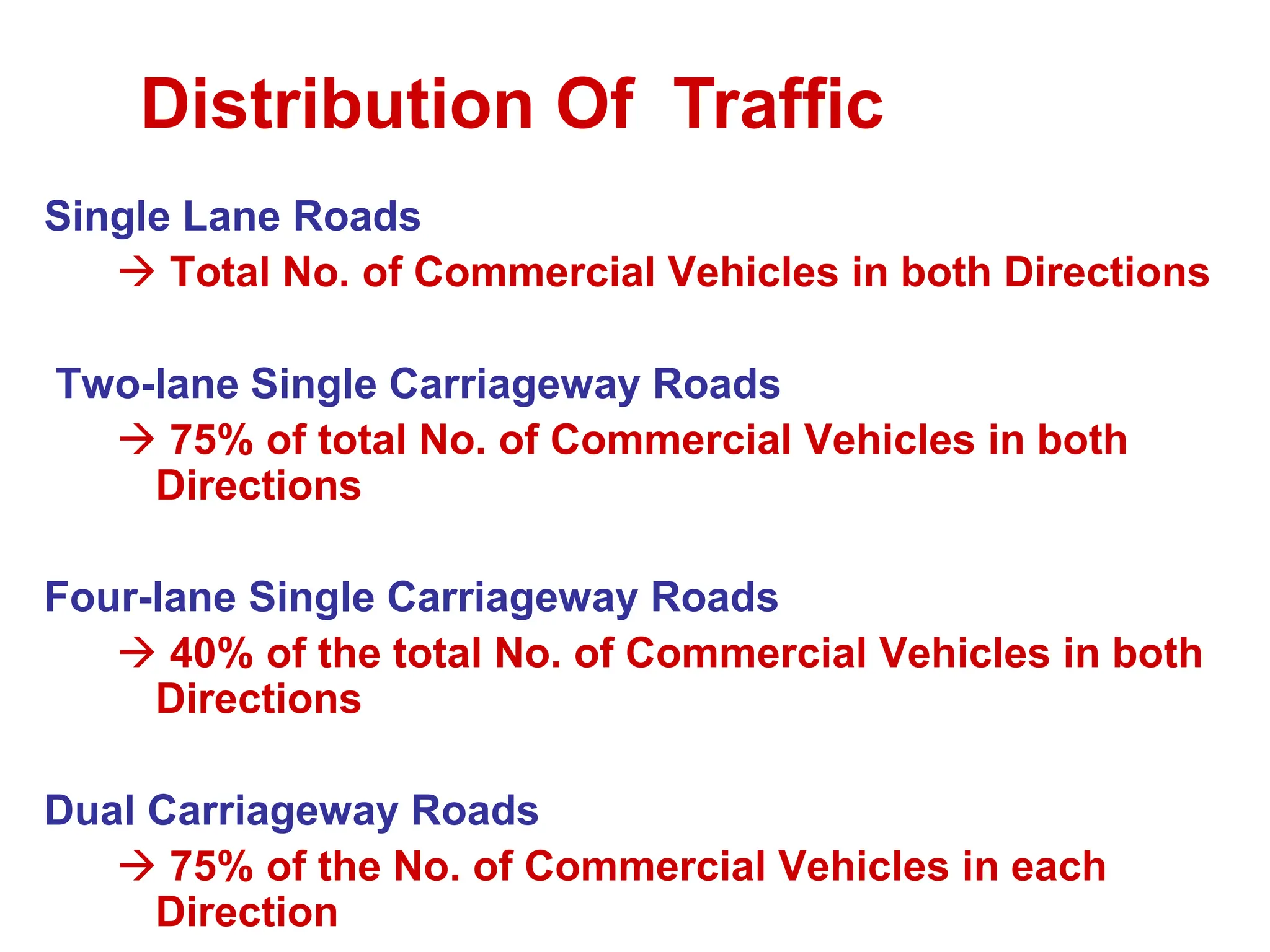
D = Lane distribution factor
A = Initial traffic, in the year of completion of construction,
in terms of number of commercial vehicles per day
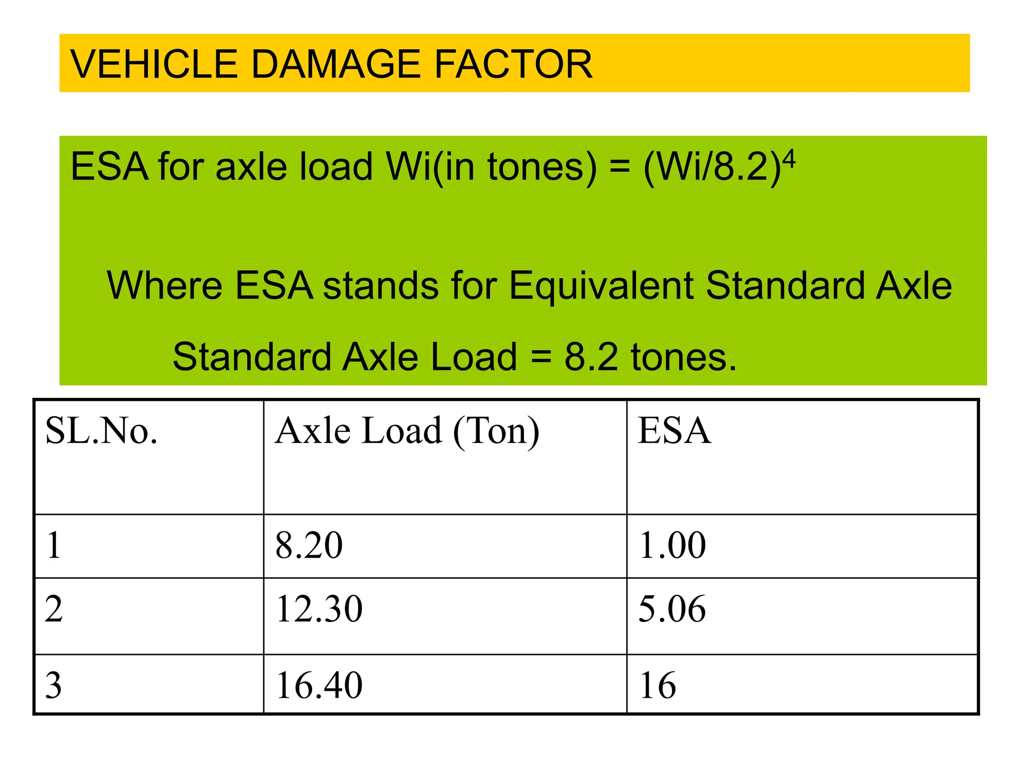
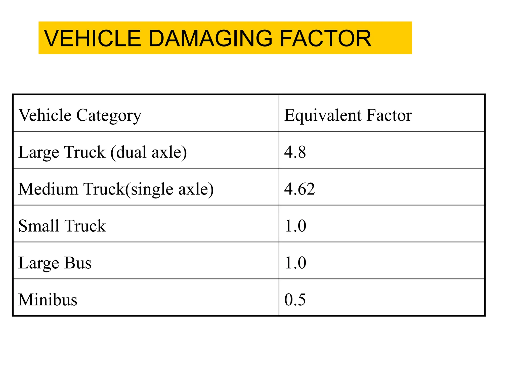
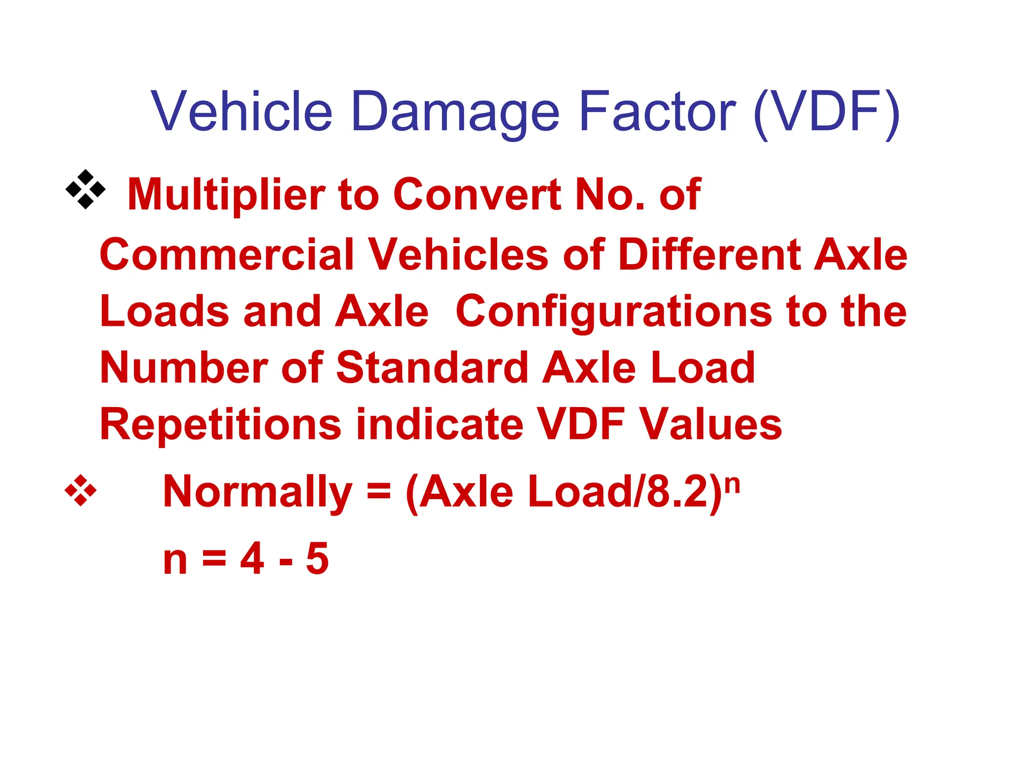
F = Vehicle Damage Factor
n = Design life in years
r = Annual growth rate of commercial vehicles](https://image.slidesharecdn.com/flexible-and-rigid-pavementspresentationinductiontraining18-240531081226-00530dc6/75/flexible-and-rigid-pavements-Presentation-Induction-training-18-02-2021-ppt-36-2048.jpg)